Note: Descriptions are shown in the official language in which they were submitted.
CA 02403298 2006-01-30
SWIVEL MOUNT FOR BOARD BINDINGS
Field of the Invention
This invention relates to a swivel connector for securing foot bindings to a
snowboard, an in-line wheel-mounted land board or the like. More particularly,
it relates to a
swivel connector that will permit the binding for the foi-ward foot to be
swivelled from a
normal ride position which is angularly disposed relative to the longitudinal
centerline of the
snowboard to a position which is substantially aligned with the longitudinal
centerl.ine of the
snowboard.
Background of the Invention
During the normal use of a riding board such as a snowboard or an in-line
wheel-mounted land board, the user places his or her feet in fore and aft
bindings which are
immovably secured to the board. The bindings are disposed at an angle to the
longitudinal
centerline of the board so that of necessity the user must adopt a side-
forward stance. For
propulsion on relatively flat terrain, for example in, the vicinity of a
chairlift loading area, the
normal procedure is to disengage the rear foot from its binding and to use
this foot to propel
the board. Since the forward. binding holds the users foot and ankle at an
angle to the direction
of travel, the user must compensate by twisting the forward knee and the upper
body into a
face forward stance in order to maintain a constant direction of travel.
Further, while riding on
the chairlift, the board is positioned at an awkward and tiring angle from the
users forward
foot.
In the prior art, applicant is aware of United States Patent No. 6,102,430
which
issued to Reynolds on May 7, 1998, for a Dual-Locking Automatic Positioning
Interface for a
I
CA 02403298 2006-01-30
Snowboard Binding. Reynolds teaches a boot binding franle 20 clamped between a
retainer
slip disk 26 positioned on an upper surface of a boot binding frame 20 and a
swivel ring 28
positioned on a lower surface. The boot binding frame 20 is fixedly secured to
swivel ring 28
for rotational movement therewith, while slip disk 26 is non-rotatively
mounted to the
snowboard 12. Thus swivel ring 28 and the boot binding frame 20 may be rotated
relative to
both snowboard 12 and slip disk 26. Rotation between the respective pieces is
permitted by a
disk receptacle or aperture 34 formed in boot binding frame 20. Since the boot
binding frame
requires a disk receptacle 34 of a substantial diameter, retrofitting of the
Reynolds device to
existing snowboard boot binding frames would. have limited application and the
most
practicable application would be the purchase of new boot binding frames
specifically
designed to cooperate with his device. In the present invention the device is
adapted for
retrofit to existing binding frarnes as the components are located beneath the
boot binding
frame eliminating the need for an equivalent to the disk receptacle 34 of
Re}n7olds, without
precluding incorporation of the present invention with new binding fraines.
Further, the locking mechanism 42 of Reynolds is detached from either slip
disk 26 or swivel ring 28 and is separately mounted to snowboard 12. Within
locking
mechanism 42 a spring urges locking detent coupler lever 44 into engagement
with swivel ring
28. To release lever 44 from engagenient with the locking detents in swivel
ring 28, lever 44
is rotated in a direction which is rotation.ally opposite to the direction of
rotation of the boot
binding frame. 20 when the frame is rotated toward the walking forward
orientation, that is, the
so-called Reynolds' soft lock position. Thus, unlike in the present invention,
the user kicking
the lever to release the ride position lock does not thereby both unlock the
swivel and apply
angular momentum to the swivelling of the user's forward foot into the forward-
walking
position.
Further, unlike the present invention, operation of the locking mechanism 42
of
Reynolds does not assist the user with repositioning of boot binding frame 20
according to the
terrain or task at hand such as dismounting a lift or against increased
resistance caused by
2
CA 02403298 2006-01-30
snow and ice which may tend to clog the swivel mechanism during use. Further,
Reynolds has
locking positions, including the forward soft lock, which does not provide for
tlie bi-
directional range of rotational resistance of the forward-walking positions of
the present
invention.
It is, therefore, an object of this invention to provide a means for
overcoming
the difficulties encountered while trying to propel a board on relatively
level terrain or in the
vicinity of the chairlift boarding and dismount area or for use on a T-bar
lift during boarding,
dismount and transition.
A further object of this invention is to provide a swivel connector for
securing
the forward binding of a board so that the user may easily reposition his
forward foot from a
ride position. to forward-walking positions.
Summary of the Invention
The swivel mount for a board binding of the present invention includes a base
mountable to an upper surface of a board, and a swivel plate rotatably mounted
on the base for
relative swivelling rotation of the swivel plate relative to the base between.
a ride position and
forward-walking positions. The swivel plate may be a separate component from
the binding or
integrally mounted into, or fonned as part of the binding.
When the swivel plate is in the ride position the binding is oriented
generally
perpendicularly to a longitudinal axis of the board. When the swivel plate is
in the forward-
walking positions, the binding is oriented to point a user's first foot, for
example the forward
foot, in the binding toward a front end of the board so as to generally form
an acute angle
between the binding and the longitudinal axis of the board. The forward-
walking positions
extend in a radial arc radially spaced from the ride position.
3
CA 02403298 2006-01-30
A non-locking, ilon free-floating rotational resistance means cooperates
between the swivel plate and the base for increasing rotational resistance
above that of free-
floating rotation but without locking of the swivel plate in a preset locking
position when
swivelling the swivel plate through the radial arc. The rotational resistance
means provides
resistance of a level between free-floating rotation having substantially no
resistance to
rotation, and locking rotational resistance requiring unlocking by a user's
hand or second foot,
for example the rearward foot, to permit rotation.
At least one ride position latch is provided for releasably locking the swivel
plate in the ride position relative to the base upon rotational urging by the
user's first foot when
the first foot is in the binding or integral with. the swivel plate so as to
return the swivel plate
from the forward walking position, to the ride position.
An actuator is provided for releasing the ride position latch. The actuator is
actuated by a force applied by the second foot in a first direction urging the
swivel plate to
swivel from said ride position to the forward-walking positions.
The actuator may comprise a flexible arm flexibly mounted to the swivel plate.
The flexible arm may have a force receiving member at a. first distal end
thereof, the first distal
end extending generally radially outwardly of the swivel plate. The ride
position latch may
coinpri,se a first pawl mounted on the flexible arm and a detent member
fixedly mounted
relative to the upper surface of the board, for example mounted to the board
or to the base.
The detent member forms a detent. The first pawl is for releasably engaging
the detent so as to
releasably lock the swivel plate in the ride position.. The flexible arm is
actuable by a force
applied generally in the first direction so as to flex relative to the swivel
plate to thereby
release the pawl from the engagement with the detent.
Alternatively, the ride position latch may comprise only a detent meil'iber
fixedly mounted relative to the upper surface of the board, the detent member
forming a
4
CA 02403298 2006-01-30
detent, and the flexible arm releasably engaging the detent so as to
releasably lock the swivel
plate in the ride position. The force receiving member, upon receiving a force
applied thereto
in the direction of rotation of the swivel. plate from the ride position to
the forward-walking
positions, flexes the flexible arm so as to disengage the flexible arm fiom
the detent. Where
the flexible arm flexes in the plane of the swivel plate, the force receiving
member may be a
rigid kick plate.
The force receiving member may be a lever for disengaging the flexible arm
from the detent by flexing the flexible arm out of a plane containing the
swivel plate. Such a
force receiving member may be a rocker arm having a fulcrum engaging an upper
surface of
the detent member forming the detent.
The resistance means may comprise a second pawl and an array of pawl
receivers lying in a rotational trajectory of the second pawl for mating with
the second pawl.
The second pawl may be mounted on the swivel plate, and the azray of pawl
receivers may be formed in the base. Alternatively, the second pawl may be
mounted on the
base and the array of pawl receivers may be formed in the swivel plate.
Further alternatively,
the second pawl may be mounted on the actuator and the array of pawl receivers
may be
formed on the base. Alternatively, the second pawl may be mounted on the base
and the array
of pawl receivers may be formed on the actuator.
Brief Description of the Drawin2s
Figure 1 is a perspective view of the swivel mount of the present invention
mounted on a snowboard in a normal ride position.
Figure 2 is a perspective view of the swivel mount of Figure 1 in a rotated
forward-walking position, substantially aligned with the longitudinaI axis of
the snowboard.
5
CA 02403298 2006-01-30
Figure 3 is an exploded perspective view of one embodiment of the swivel
mount of the present invention.
Figure 4 is a sectional view taken on line 4-4 of Figure 2.
Figure 5 is a plan view, partially in section, illustrating the swivel mount
of
Figure 1.
Figure 6 is a plan. view, partially in section, of the swivel mount of Figure
2.
Figure 7 is an isometric view of an alternative embodinient of the present
invention.
Figure 8 is a sectional view taken on line 8-8 of Figure 7.
Figure 9 is an isometric view of an alternative einbodiment of the present
invention.
Figure 10 is a sectional view taken on line 1.0-10 of Figure 9.
Figure 11 is an isometric view of an alternative embodiment of the present
invention.
Figure 12 is a sectional view taken on line 12-12 of Figure 11.
Figure 13 is an isometric view of an altemative embodiment of the present
invention.
6
CA 02403298 2006-01-30
Figure 14 is a sectional view taken on line 1.4-14 of Figure 13.
Figure 15 is a plan view of an aiteniative einbodiment of the present
invention.
Figure 16 is an enlarged view of the rotation arresting device of Figure 15.
Figure 17 is a plan view, partially cut-away, illustrating the alternative
rotation
arresting device of Figure 15 incorporated into a binding of a snowboard.
Figure 18 is an isometric view illustrating an alternative means for securing
the
swivel plate lever in the ride position.
Figure 19 is a sectional view taken on line 19-19 of Figure 18.
Figure 20 is a partial front view of a snowboard binding, illustrating one
form
of spring actuated braking lever.
Figure 21 is an isometric view of an alternative form of spring actuated
braking
lever.
Figure 22 is an enlarged isometric view of the alternative form of spring
actuated braUig lever of. Figure 21.
Figure 23 is an isometric view of an alternative embodiment of the present
invention.
Figure 24 is a sectional view taken on line 24-24 of Figure 23.
Fig re 25 is, in plan view, a further embodiment of the ride position latching
7
CA 02403298 2006-01-30
mechanism of the swivel mount of the presen.t invention.
Figure 26 is, in partially cut-away perspective view, the ride position latch
mechanism of Figure 25.
Figure 27 is a cross-sectional view along line 27-27 in Figure 26.
Figure 28 is a partially cut-away cross-sectional view of an alternative
embodiment ride position latch releasing mechanism corresponding to the view
of Figure 27.
Figure 29 is, in partially cut-away perspective view, a further alternative
embodiment of the forward-walking position resistance mechanism of Figure 25.
Figure 30 is a cross-sectional view taken along line 30-30 in Figure 29.
Figure 31 is, in partially cut away plan view, a board braking mechanism
niounted to a swivel plate according to the present invention when rotated
into a forward
walking position.
Figure 32 is the view of Figure 31 with the swivel plate rotated into the in-
line
forward-walking position.
Figure 33 is a cross-sectional. view along line 33-33 in Figure 31.
Figures 34-36 correspond to Figures 31-33 in an embodiment where the braking
mechanism is mounted to the binding.
Figure 37 is, in partially cut-away perspective view, a further embodiment of
the ride position latch of the swivel mount of the present invention.
8
CA 02403298 2006-01-30
Figure 38 is a partially cut-away cross-sectional view along line 38-38 in
Figure
37.
Figure 39 is, in partially cut-away perspective view, a further alternative
embodiment of the present invention in the ride position.
Figure 40 is the swivel mount of Figure 39 in a forward-walking position.
Figure 41 is, in enlarged partially cut-away perspective view, an alternative
enibodiment of a ride position latch release.
Figure 42 is a sectional view along line 42-42 in Figure 41.
Figure 43 is the latch release of Figure 42 releasing the latch.
Detailed Description of Embodiments of the Invention
As used herein, reference to snowboard or board is meant to include all fonlls
of riding boards whether for use on snow, or on soft or hard terrain, flat or
rough, whether the
board slides on its under-surface or rolls on wheels, tracks or other conveyor
means. Further,
as used herein, reference to a user's forward foot or rearward foot or
reference to a forward
binding or rearward binding are intended to be interchangeable. That is,
although described in
relation to the normal situation where a user removes the rear foot from the
rear binding during
use of an uphill lift or during flat terrain translation, the scope of the
present invention is
intended also to cover the reverse, where a user instead removes a forward
foot froln the
forward binding.
9
CA 02403298 2006-01-30
As seen in Figures I and 2, swivel mount 10 is mounted to upper surface 12a of
a board 12 at the location where the forward binding 14 is to be mounted.
Mount 10 has a
relatively low side-on profile so as to be raised only minimally above upper
surface 12a. A
user may choose to secure a disk shaped spacer (not shown) of similar
thickness beneath the
rear binding to provide a level stance.
As seen in Figures 3 and 4, connector 10 includes in one embodiment a swivel
housing 16 which may be mounted to snowboard 12 by screws 16a. Swivel housing
16 has a
base 18 and an upstanding annular perimeter wall 20 which define a cavity 22
therebetween.
Perimeter wall 20 is formed with annular shoulder 20a on its exterior surface.
This results in a
slightly recessed upstanding annular collar portion 20b. Slot 24 in wall 20 is
positioned
between base 18 and shoulder 20a, parallel to the base.
A swivel plate 30 is rotatably mounted within cavity 22 of housing 16. A
loclcing lever 32 projects laterally outward from plate 30. Locking lever 32,
which in all
embodiments of locking levers or arms herein may be manufactured from a
resilient material
such as spring steel or robust plastic, extends outward through slot 24 formed
in perimeter wall
20. Swivel plate 30 is formed with an inwardly turned annular shoulder 30a on
the exterior
surface, which results in an annular outer surface 30b defining an upper
planar surface 33. The
upper edge of wall 20 extends slightly above annular shoulder 30a on swivel
plate 30. Upper
planar face 33 has a plurality of threaded holes 34 enabling binding 14 to be
rigidly bolted
thereto. A recess 35 may be formed on the underside of swivel plate 30 to
reduce surf.ace area
contact with base 18.
A locking ring 36 having an annular upper surface 36a and a contiguous
annular depending sidewall 36b is mounted over swivel housing 16. Depending
sidewall 36b
slides over recessed, upstanding annular collar portion 20b formed on
perimeter wall 20 of
swivel housing 16 until sidewall 36b contacts annular shoulder 20a and the
upper face 33 of
cylindrical swivel plate 30 projects slightly outwardly of upper surface 36a
of locking ring 36.
CA 02403298 2006-01-30
Locking ring 36 is secured to housing 16 with setscrews 38. Annu.lar upper
surface 36a
extends radially inwardly so as to be in proximity to annular outer surface
30b of swivel plate
30 to inhibit snow and moisture incursion.
As seen in Figures 5 and 6, perimeter wall 20 has at least one primary detent
40
at a first end of slot 24 and a plurality of secondary detents or protrusions
40a formed at the
opposite second end of slot 24. Although only two primary detents 40 are
illustrated, this is
not intended to be limiting as it may be desirable to have more than merely
one or two latching
ride positions. Thus in all of the embodiments herein, it is expressly
intended to be within the
scope of the invention to include a plurality of ride position latches,
radially spaced from one
another, to allow for a user to select a desirable or comfortable ride
position.
Locking lever 32 has oppositely disposed arcuately curved arms 44 and 44a
which extend laterally outward of the lever, adjacent to wall 20. A pawl 48
projects from the
distal end of each of the amis for firmly engaging detents 40 and 40a. Pawl 48
on arm 44
engages priinary detent 40. Pawl 48 on arm 44a engages secondary detents 40a.
Because
binding 14 is mounted to swivel plate 30, rotating lever 32 so as to engage
pawis 48 with
either detents 40 or 40a also correspondingly rotates binding 14. Thus the
binding may be
rotated by a user so as to latch into a ride position when pawl 48 on arm. 44
is mated behind
primary detent 40. Reference to the ride position herein connotes the normal
angular
orientation of bindings 14 for riding on the board, that is, substantially or
generally
perpendicular to longitudinal axis A'.
Figure 5 illustrates binding 14 (in dotted outline) positioned at an angie %
relative to the longitudinal axis A' of the snowboard 12. Paw148 on ann 44 is
latched behind
detent 40. Again, this angular orientation of binding 14 relative to board 12
is intended to
indicate the normal "ride" position of a user's foot when the user is riding
on. the board with the
user's foot mounted to the board by the binding. Unintended rotation in
direction B of binding
14 out of the ride position, so as to point the foot of the user toward the
front of the board
11
CA 02403298 2006-01-30
along longitudinal axis A' of snowboard 12, i.e., so as to reduce angle %, is
prevented by the
engagement of pawl 48 on arm 44 with detent 40. Rotation of binding 14 toward
the
longitudinal axis of snowboard 12, is enabled by deflecting or bending or
flexing locking lever
32 in direction B so as to rotate the binding about rotation axis B'. This may
be accomplished
for example by pushing against or kicking the radially outwardly distal end of
lever 32 in.
direction B, against the inherent return biasing resiliency of the material
such as spring steel
from. which the lever is manufactured. Where a plurality of primary detents 40
are provided
radially spaced apart on wall 20, the user may select the desired primary
detent so as to select a
desired angle for the side-forward stance ride position.
To ease mobility on the board when not riding, for example when on relatively
flat terrain, or for example in the vicinity of the chairlift boarding or
dismount area, or for use
in association with a T-bar lift, and without entirely removing the board from
the user's feet,
normally only the user's rear foot is removed, that is, extracted from the
rear binding. This
frees the rear foot of the user to engage, for example by kicking in direction
B, the distal end
of locking lever 32. Lever 32 is kicked on the side opposite to the intended
direction of
rotation of binding 14. When kicked, lever 32 is deformed so as to rotate pawl
48 radially
outwardly of wall 20, to free latched contact of pawl 48 with detent 40. Using
either or both of
the initial kicking force and continued foot pressure against lever 32,
binding 14 and swivel
plate 30 are then fiirther rotated in direction B to the toe forward or
forward-walking positions
or orientations of Figure 6 where angle % is reduced from the ride position to
an acute angle.
The available range of motion will depend on the desired range of angular
rotation desired for
use in the forward walking positions as described better below.
In the forward-walking positions the user's forward foot and ankle in binding
14
is under less angular strain than in the ride position when the rear foot is
used to peddle for
forward motion. Accordingly, the detent and pawl securing binding 14 in the
forward-walkiiig
positions need not provide, and it is not desirable that they provide, the
same degree of angular
retention or resistance to rotation as the corresponding detent and pawl for
retention of the
12
CA 02403298 2006-01-30
binding in the ride position. As illustrated, detents 40a are rounded,
permitting rotation of
binding 14 in a direction opposite to direction B without the need for foot
pressure using the
rear foot against locking lever 32, that is, permitting rotation of binding 14
towards the ride
position solely due to the force exerted by the user in rotating the forward
foot so as to either
adjust to the desired angle % in. the forward-walking position or to return
the binding to latch
into the board riding position.
Alternative embodiments for partially impeding or resisting the free-floating
rotation of swivel plate 30 relative to the board once pawl 48 on locking
lever 32 is freed from
latched engagement behind detent 40, and for retaining the swivel plate in a
desired foitivard-
walking position, are illustrated in Figures 7 through 1.7, Figures 23 through
30, and Figures
37 through 43.
As seen in Figure 7, lever 80, integrally formed with swivel plate 80a, has
been
rotated slightly in. direction B by impact from the user's rear foot (not
shown). The impact has
resulted in a flexure of lever 80 about neck 81, so as to translate pawl 82
and arm 80b in
direction P resulting in disengaging paw182 from detent 84 mounted on lower
plate 86. In this
position further rotation in direction B, toward the forward-walking
positions, is accomplished
by a twisting motion in direction B of the user's forward foot (not shown),
i.e. the foot held
within binding 14 when mounted on swivel plate 80a.
Arm 90 extends from locking lever 80 in the plane of swivel plate 80a. Arm 90
extends arcuately, generally in the direction of rotation B. Aril'i 90 has
formed on its und.erside
an array of recesses 92 (shown in dotted outline) which engage, so as to mate
with, a
protrusion or pawl 94 projecting from the upper surface of lower plate 86.
Protrusion 94 may
as seen in Figure 8 be in the form of a cavity 94a containing a sphere, such
as a ball bearing,
96. Sphere 96 may be urged by spring 98 so as to project slightly from the
open end of cavity
94a above the upper surface of lower plate 86. Otllerwise protrusion 94 may be
a rigid
projection or bump relying on the resiliency of arm 90 to allow sliding of the
recesses into
13
CA 02403298 2006-01-30
mating engagement with the projection or bump. As described herein, any
protrusion, ball,
spllere, bump or rigid projection intended to engage a mating recess or array
of recesses, may
also be collectively refeired to as a pawl.
Engagement of sphere 96 with any one of recesses 92 impedes the free rotation
of swivel plate 80a as the swivel plate is rotated through the arc defined by
the length of the
array of recesses 92. This coincides with the desired arc of the forward-
walking positions of
binding 14. Thus in the forward walking positions, the swivelling of swivel
plate 80a and
hence the orientation of the forward foot may be selected, and actively
adjusted by the user to
a comfortable toe forward orientation.
In Figures 9 and 10 the arrangement of recesses 92 and protrusion 94 is
reversed. Arm 90 contains protrusion 94. In this embodiment, sphere 96 is
urged by spring 98
to project slightly from the underside of arn? 90 to resiliently engage
recesses 92 formed on the
upper surface of lower plate 86.
As seen in the embodiment illustrated in Figures 11 and 12, arm 90 extends
from locking lever 80 at a radius from the rotation axis B' which exceeds the
radius of the
outer edge of bottom plate 86. As locking lever 80 and arm 90 are rotated in
direction B,
protrusion 94 mounted on the upper surface of board 12 will be engaged. Sphere
96 engages
recesses 92 on the underside of arm 90 to partially impede or lend resistance
to the free-
floating rotation of swivel plate 80a about axis B'.
Illustrated in Figures 13 and 14 is an embodiment where arm 90 and locking
lever 80 are integrally formed with the sole of binding 100 so as to project
radially outwardly
therefrom. Arm 90 has an array of recesses 92 fonned on. its underside.
Rotation of the
bindings 100, in direction B, brings the circular trajectory of arm 90 into
alignment with
protrusion. 94 projecting from the upper surface of board 12. Frictional
engagement of any oiae
14
CA 02403298 2006-01-30
of the array of recesses 92 with sphere 96 partially impedes or resists the
free-floating rotation
of the binding and swivel plate relative to the base plate.
In Figures 15 and 16 recess 102 formed adjacent to detent 84 frictionally
engages convolutions 104 in opposed facing relation on the end of lever 80
adjacent swivel
plate 80a. Detent 84 is rigidly mounted to board 1.2 and pawl 82 must be
rotated past recess
102, in direction B, before convolutions 104 are brought into engagement so as
to mate in
succession with recess 102 as the swivel plate and binding are rotated through
the radial arc
comprising the forward-walking positions.
Figure 17 illustrates the device of Figures 15 and 16 fornned as part of a
binding
100. Binding 100 may be molded around a portion of lever 80 such as elongated
arm 106. It
is expressly intended to be within the scope of the present invention that the
swivel plate may
be a separate component or an integral component integrally mounted or formed
within the
forward binding.
Figures 18 and 19 illustrate an alternative fomi of locking detent for lever
80.
In this form, detent 84' is formed on a rotatable clip latch 108 mountable
either to lower plate
86 or to the upper surface of the board. In the closed position, clip latch
108 clamps or grips a
portion, for example the end of lever 80, to retain binding 14 in the ride
position. Clip 108
may be resiliently urged by a spring (not shown) to its closed position.
Figures 20 through 22 illustrate optional spring operated. brake arms intended
to
prevent dismounted boards from careening downhill. A run-away board on a steep
slope may
attain a speed which may cause serious injury should the board collide with a
person, or
damage to the board should it strike a solid object.
Figure 20 illustrates a brake mechanism 110 wllich is pivotally mounted to a
board adjacent to a binding, for example a binding 100. Brake 110 is held in a
retracted
CA 02403298 2006-01-30
position, as shown in broken lines, by securing the free end of a flexible
tether 112 to a lace of
a boot. Tether 112 may be resilient such as of elastic cord. Upon release of
tether 112 from
the boot lace, as would be the case when the user steps out of binding 100,
spring action pivots
brake mechanism 110 to the deployed position illustrated in solid lines. Brake
arm 114 is
sufficiently long so that, in the deployed position, the downwardly projecting
distal end
portion of brake arm 114 extends sufficiently below the underside of the board
to dig into the
surface over which the board is riding to inhibit run-away of the board.
In Figures 21 and 22 an alternative spring loaded braking mechanism 120 is
shown having a pressure paddle 122 at one end of a rotatable shaft 124 and a
brake arm 126 at
the opposite end. Paddle 122 is rotated to elevate brake arni 126 so that
paddle 122 lies within
a heel cut-away portion of the binding. Placement of a foot within the binding
maintaiuis brake
arm 126 in the elevated position. Removal of the foot from the binding allows
180 degree
rotation of paddle 122 and brake ann 126 by action of spring 128 to extend the
end portion of
arm 126 below the underside of the board to dig into the terrain surface.
Illustrated in Figures 23 and 24 is an embodiment which incorporates an
integrally formed resistance device 130 within the sole of binding 100.
Rotation of the
binding in direction B brings sphere 96, protruding from resistance device
130, into arcuate
aligmnent with recesses 132 on bar 134. Bar 134 is rigidly mounted on the
upper surface of
the board. Engagement of any one of the series of recesses 132 with spring-
loaded sphere 96
partially impedes the free-floating rotation of the binding without fixedly
locking rotation so
that manual intervention by hand is needed to adjust the forward-walking
position.
Figures 25-27 illustrate a fiu-ther alternative embodiment of the swivel mount
ride position latch mechanism. In particular, anii 140 extends resiliently
from swivel plate 142
for rotation in direction B so as to rotate binding 14 relative to snowboard
12. Arm 140 is
illustrated latched in the ride position, the distal end of ann 140 releasably
snugly mated
between opposed facing wedges 144a and 144b. Wedges 144a and 144b are rigidly
mounted
16
CA 02403298 2006-01-30
to board 12 for example by fasteners such as bolts or screws 146. Ann 140 may
be unlatched
from mating engagement between wedges 144a and 144b by a user lifting the
distal end of arm
1.40 against the return resilient biasing force of the arm, so as to lift it
above the uppermost
edge of 144a thereby allowing rotation of arm 140 in direction B over wedge
144a. Lifting of
artn 140 may be done by a user grasping and pulling upwardly on knob 147. The
use of knob
147 is not intended to be limiting and in a furth.er embodiment is replaced by
foot actuable
device, for example where knob 147 is replaced by a toe cup (shown in dotted
outline as a cut-
away from. the knob) mounted to the distal end of arm 140. In this embodiment
the rear foot
of the user may be used to engage the toe cup and then simply lift the toe cup
with the rear foot
so as to disengage arm 140 from wedge 144a allowing the rear foot of the user
to then urge
aim 140 in direction B so as to rotate binding 14 into the forward-walking
positions.
In the forward-walking positions, a downward protrusion from arm 1.40, for
example spring loaded ball 148, engages recesses 150 in curved bar 152 mounted
to board 12.
The resilient mating engagement of the protrusion such as spring loaded ball
148 from the
bottom of arm 140 resiliently mates with recesses 150 as binding 14 is rotated
in direction B
by the rotation of the forward foot of the user and by reason also of any
rotational momentum
imparted by the rear foot of the user if used to unlatch arm 140 from the ride
position.
It is to be understood that whether the downward protrusion from arm 140 i,s
resiliently mated with recesses 1.50 because of the resilient bending of arm
140 or the resilient
compression of spring 154 within housing 156, the end result is that the
relative position of
binding 14 relative to board 12 may be adjusted by manual rotation of the
user's forward foot
so that the user may adjust into a comfortable forward-walking position
dependi.ng on whether
the user is forwardly translating by pedalling with the free rear foot, or
exiting from a chair lift
down an inclined ramp or otherwise in transit where temporarily the terrain is
downwardly
inclined so that the user may ride on the board, the terrain such that
intermittent pedalling is
still needed. Thus the user may quickly shift from a comfortable in-line
forward-walking
position to an angularly offset forward translating position while still
remaining within the
17
CA 02403298 2006-01-30
forward-walking range of positions.
During forward translation, when not pedalling, the rear foot may be placed on
the board for example between the forward and rear bindings. Typically a no-
slip pad is
installed on the board between the bindings expressly for temporary frictional
engagement
between the board and the rear foot of the user.
Collectively herein, all of the so-called forward-walking positions, including
the straight in-line position which is perhaps the most comfortable for
forward transit using the
rear foot to pedal the board in a forward motion, and what is described herein
loosely as within
an acute angle from the in-line position, are all encompassed within the
generic term forward-
walking positions. Consequently a user, once un-latched from the ride
position, may enter the
range of forward-walking positions irninediately radially adjacent the ride
position. Thus
when exiting a chairlift the user may, for example while on the chairlift,
have positioned the
forward foot and binding into a position very close to the ride position. This
gives the user a
fan-iiliar ride feel when riding down the off ranlp. Once off the ramp, the
user may then latch
into the ride position for downhill riding.
Thus the latch mechanism for holding binding 14 in the ride position will be
located in a radial position relative to the swivel plate so as to not
interfere with the resilient
engagement of the rotational resistance mechanism engaged in the forward-
walking positions.
The latch mechanism also should not protrude from the board surface so as not
to interfere
with use of the board while either riding or translating when the binding is
in the forward-
walking positions. Consequently, where the ride position latch mechanism is an
arm
protruding from the swivel plate, generally the arm will be positioned
radially spaced from the
rotational resistance mechanism in the forward-walking positions. Thus as seen
in Figures 29
and 30, the forward-walking position resistance mechanism includes curved bars
158
extending from arm 140, each bar 158 having recesses 160 on its under surface
so as to engage
a protrusion protruding upwardly from board 12 such as spring loaded ball 162.
18
CA 02403298 2006-01-30
As seen in Figure 28, a foot operated release such as rocker arm 164 may be
mounted to board 12 and employed to release arm 140 from between wedges 144a
and 144b.
Thus, with cantilevered end 164a of rocker arm 164 positioned between the
wedges and
underneath the distal end of arm 140 when latched in the ride position, the
rear foot of the user
may be used to press down on upturned end 164b about fulcrum mount 166 so as
to engage
cantilevered end 164a with the underside of arm 140. This elevates the distal
end of arm 140
above wedge 144a allowing for rotation of the binding in direction B from the
ride position
into the forward-walking positions.
Figu.res 31-33 illustrate a board bralcing mechanism 170 mounted to swivel
plate 172. The brake mechanisin has a resiliently urged arm 174 pivotally
mounted for
example for pivotal movement about spring 176 relative to base member 178 on
swivel plate
172. Within the range of typical ride positions such as illustrated in Figures
31 and 32, base
member 178 extends from beneath binding 14 so as to dispose arnl 174 for
deployment over
the left hand edge 12b of snowboard 12.
Arm 174 may, without intending to be Iimiting, be bent into a Z-shape so that
when foot pressure of a user's forward foot in. binding 14 is removed from
pressing down on
end 174a of ann 174, spring 1.76 then resiliently urges the opposite end 174b
away fi-om
binding 14 into a downwardly disposed position engaging the terrain beneath
board 12.
In Figures 34-36, arm 174 operates in a similar fashion to the embodiment of
Figures 31-33, but is however mounted directly to binding 14 instead of
mounted to swivel
plate 172.
In the embodiznent of Figures 37 and 38, arm 140 on swivel plate 172 is
latched
in the ride position within slide housing 180. The cavity witbin slide housing
180 captures the
distal end of arm 140 when slide housing 180 is slid radially inwardly
relative to swivel plate
19
CA 02403298 2006-01-30
172 along linear track 182 formed within rigid member 184 extending from base
18. In the
embodiment illustrated, the forward-walking position resistance mechanism
includes upwardly
protruding pawls such as bunips or protrusions 186 in a curved array so as to
engage a
corresponding recess 188 formed on the underside of arm 140 as arm 140 is
rotated in
direction B from the ride position into the forward-walking positions. As
before, it is not
intended to be limiting that the pawl protrusions are mounted on the base
plate and the recess
on the swivel plate, as it is intended to be within the scope of the present
invention that the
recesses may be formed in the base plate and the pawl protrusion for mating
with the recesses
be formed on the swivel plate.
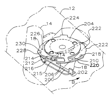
As seen in Figures 39 and 40; kick arm 200 has rigidly mounted at its distal
end
a kick plate 202. The radially inward end of kick arm 200 is mounted to swivel
plate 204 by
resilient flex arm 206. The amount of flexing of flex arm 206 when kick plate
202 is kicked
by a user's rear foot is limited by stop arm 208 engaging the base arm 210
extending from the
swivel plate.
Ride position latch pawl 212 protrudes radially inwardly from the inner end of
kick arm 200 so as to engage one of the ride position detents 21.4 on the
detent member 215
mounted to base plate 18. The user selects which detent 214 to use, for
example which is most
comfortable or best suited to the desired board riding.
When kick arm 200 has been rotated in direction B from the ride position to
the
forward-walking position, pawl 218 mounted on the end of flex arm 220 engages
a radially
spaced array of recesses, convolutions, corrugations or teeth 222 radially
spaced ar.ound base
18.
Flange 224 extends rigidly from swivel plate 204 so as to engage stop 226 as
binding 14 on swivel plate 204 is rotated into the in-line forward-walking
position.
CA 02403298 2006-01-30
A secondary flex arm 228 may be provided which extends from the radially
innerrnost end of kick arm 200. Secondary pawl 230 is mounted at the distal
end of secondary
flex arm 228 so as to engage a protrusion mounted to base plate 18 or board 12
such as detent
214. Secondary pawl 230 is radially spaced on secondary flex arm 228 so tliat,
as kick arm
200 is rotating in direction B, secondary pawl 230 disengages from detent 214
once pawi 218
is in. engagement with teeth 222, that is, begins rotating through the forward-
walking positions.
Secondary pawl 230 thus provides tactile feedback to the user indicating for
example the mid-
range or the end of range of motion in the forward-walking positions. Over-
rotation of
secondary flex arm 228 is prevented by stop 216. Pawl 230 may further provide
a resiliently
biased increase in rotational resistance as swivel plate is rotated in a
direction opposite to
direction B to indicate to the user that the binding has been rotated to, for
example, the mid-
range or the limit of travel within. the forward-walking positions. If the
user then desires to
continue rotation of the binding so as to return to the ride position, the
slightly increased
rotational resistance provided by secondary pawl riding over detent 214 is
overcome by the
user deliberately twisting the forward foot.
In the embodiment of Figures 41-43, ann 140 on swivel plate 142 in the ride
position is again mated behind wedge 144a. I.n this enlbodiment however,
instead of the use of
a knob 146 or toe cup, or the use of a rocker arm to release the distal end of
arm 140 from
being latched in the ride position behind wedge 144a, a rocker arm 190 is
mounted to arni 140
for example by means of hinge 192 so as to extend over wedge 144a for rotation
about axis C.
Rocker ann 190 may be resiliently urged down onto wedges 144a by a spring (not
shown).
Rocker arm 190 has at its opposite end to hinge 1.92 an. upturned toe catch
194 so that a force
applied downwardly on toe catch 194 rotates rocker arm 190 about axis D, being
the pivot
point of fulcrum 196 resting on wedge 1.44a. Rotation of rocker arm 190 about
fulcrum 196
elevates arm 140 above wedge 144a so as to release arm 140 from latched
engagement in the
ride position behind wedge 144a.
Thus for a user to unlatch binding 14 from the ride position, the toe of
21
CA 02403298 2006-01-30
the user's rear foot may be used to engage toe catch 194 so as to both rotate
rocker arm 190
about fulcrum 196 and, once arm 140 is released from behind wedge 144a, to
slide rocker arm
190 and thus ami 140 in direction B thereby assisting the rotation of binding
14 into the
for.ward-walking positions. The pressing down onto toe catch 194 may be a
discrete first
movement by the user's rear foot then followed by a sliding of the rocker arm
in direction B, or
the movement by the user's rear foot may be a combined pressing down and
sliding, for
example so as to direct a force applied by the user's rear foot in direction
A' to simultaneously
rotate rocker arm 1.90 freeing arm 140 and rotating arm 140 in direction B by
reason of the
force vector component in direction A.
As will be apparent to those skilled in the art in the light of the foregoing
disclosure, many alterations and modifications are possible in the practice of
this invention
without departing from the spirit or scope thereof. Accordingly, the scope of
the invention is
to be construed in accordance with the substance defined by the following
claims.
22