Note: Descriptions are shown in the official language in which they were submitted.
CA 02403543 2004-12-17
1
Method and Apparatus for Joining Sheet or Ribbon Formed
Flows in a Coextrusion Process
The invention concerns a method of coextrusion of
the type defined in the pre-characterizing part of Claim
1 and an extruder comprising a coextrusion die according
to the pre-characterizing part of claim 27. A method and
an extruder of similar type is known from e.g. US-A-
4,469,475 or DE-B1082043. It is applicable to the
extrusion of generally all materials which can be
extruded, such as e.g. thermoplastic polymers, inorganic
pastes, for instance for forming ceramic materials, and
several kinds of foodstuff.
The invention has three different aspects in
connection with three different objectives. One aspect
("the first aspect") concerns the use of coextrusion for
cover, on one or both sides, of an extrudable material A
which during the extrusion has a high apparent viscosity,
with a thin layer or thin layers of a material B having a
much lower apparent viscosity. In such cases the cover
will normally become very uneven or may even be missing
over a part of the surface, when conventional technology
is used, because the energy required to make B flow
evenly distributed in a thin stream is higher than that
required to make B flow in narrow thicker streams.
Another aspect of the invention ("the second
aspect") concerns coextrusion of sheets or pipes in which
segments of one component alternate with segments of
another component, the alternation taking place along the
direction of extrusion. As an important example this can
be a pipe in which stiff segments alternate with flexible
CA 02403543 2004-12-17
la
segments (the relative stiffness being referred to being
in the product).
Still another aspect of the invention ("the third
aspect") concerns coextrusion of a flow of solid
generally dry particles with a flow of truly fluid
material in such a way that the fluid material becomes
absorbed in the flow of solid particles (that is becomes
blended with the solid particles).
15
25
CA 02403543 2006-01-19
2
As an important example this can be a method of
blending Tetlon Tm (polytetrafluoroethyle.ne PTFE) particles
with molten polyxLmide and extruding sheets, ribbons or
pipes from the blend. Furthermore this aspect of the
invention can be used to produce special ceramic products,
especa.ally porous products, through a process in which
solid inorganic particles e.g. comprising short
reinforcement fibres become blended with a prepolymer,
which later is cured, or with an aqueous solution or
dispersion of an inorganic material which after drying and
heat treatment will act as a binder. in an analogous way,
the third aspect of the invention can be used to coextrude
a strand of medial material, which can be chopped up to
pills.
US-A-3, 761,211 (Parkinson) , US-A-4, 152, 387 (Cloeren),
US-A-4,197,069 (Cloeren) and US-A-4,533,308 (Cloeren)
address the problem how to avoid or minimize what ir,
Cloeren's patents is referred to as "the curtaining
effect", i.e. a profiling of coextruded film which appears
aa a transverse line pattern formed where two sheet-formed
flows join each other if these flows have different
rheologies, and especially if they are aZso coextruded in
about equal amounts. These four patents make use of one or
more flaps, which can be pivoted and which end where the
flows join each other. The first mentioned three patents
have means for adjustment of the flaps, so that the ratio
between the velocities of the flows where they meet, can be
adapted to the rheological properties and the throughputs
of the components. The last mentioned patent makes use of
one or more free floating, pivoting flaps, which
automata.cal adjust to different rheologies and throughputs
of the components, namely so that the pressure becomes the
same on the two sides of a flap. The "curtaining effect"
which these four patents counteract is a. problem different
from the problem which the first aspect of the present
a.zlvention addresses (see abave) , and which results in a
longitudinal instead of transverse striation. The inventor
of the present invention has found by experimentation that
the precautions disclosed in the mentioned four patents do
not solve the said problem.
CA 02403543 2006-01-19
2a
US-A-4,469,475 (Krysiak) discloses an extruder
suitable for making food products comprising a core and
an encrusting shell. The extruder comprises a closure to
prevent the encrusti.ng material flowing into the
paasageway through which the filling is extruded. The
closure is close to the exit from the extruder.
In WO-A-0060959, there ie a description of an
extruder and a method falling within the acope of the
claims of the present application. The subject matter is
entitled to priority from the filing date of the PCT
application, from which the present application claims
priority. The disclosure does not constitute prior art
to the claims of the present application therefore.
The three different objectives are basically
achieved each by similar means, namely by providing a new
method of coextruding a sheet- or ribbon formed flow of
extrudable material A with a sheet- or ribbon formed fXow
of extrudable materia3, 8 in a zone of joining iaci a
Coextrusion die (which term includes an adaptor upstream
of the final product forming die) in which B is extruded
on A through a port and the two materials proceed
together through a passageway towards an exit of the dxe,
wherein the separation wall between said flows,
immediately before it ends in port is formed as a flap
closure adapted to act as no-return valve for the flow of
B onto A, characterized in that the extrusion of B
through takes place in pulses.
Furthermore, these objectives are achieved by the
extruder as defined in claim 27.
Particular embodiments of the i.nvention are the
subject of the respective dependent claims.
CA 02403543 2006-01-19
2b
In the first aspect of the izxventipn the pulsations
take place shock-like to distribute B evenly on A over
the length of port, and the irregularities along the
direction of flow produced by the pulsationa are evened
out, at least in part, during the comrnon flow of
components A and B through the end of the coextrusion die
- as further dealt with below.
In the second aspect of the invention, the pxocess
is adapted to make the flap closure (or closures, if
there is coextruded 8-material onto both sides of A) act
as shutters which ratop, at least substantially, the flow
of A during
CA 02403543 2006-01-19
3
each pulse of B-extrusi.on. This adaption is also deal.t with
in further detail below. in the third aspect of the
invention A is propelled by means of a ram directly
upstream of the location where the flows are joined.
S In the present specification, a flap or a flap closure
refers to a component which is pivoted or tethered along
one side and which can move about the pivot, for instance
under influence of actuating means or pressure from fluid
exerted on the flap. In each of the three aspects of the
invention the flap closure is preferably substantialIy flat
and is generally a springy blade, optionally with a thicker
or harder section at its downstream end . The
springy blade can be of steel or other suitable metal and
can even be made of a rubber material if the temperature of
is extrusion is sufficiently low to allow this. The optional
thicker or harder section at the downstream end serves to
stabilize the opening and closing of the flap and may be
almost mandatory if a rubbcr material is chosen to act as
flexible blade (hinge). The pulsation in the flow B is
normally best effected upstream of the flap closure by one
or more rams or by opening and closing valves.
Alternatively, this pulsation can be effected by opening
and/or closing the flap closure through mechanical
transmission means. 'T'lie former option .i,s illustrated in
the figures.
in order to achieve the most regular merging of the
components A and B, they should preferably both be planar
flows at least in the immediate vicinity of the part where
they merge and here be generally parallel to the flap.
The invention can immediately be applied to
coextrusion of a flat sheet, or ribbon from a flat
coextrusion die while the application in a
circular die may require special precautions taken. In such
circular dies the components usually (but not in al3, cases)
flow in a generally axial direction at the location where
CA 02403543 2006-01-19
4
they are joined ffind the wall which separate the components
before the joining ends in a generally circular cylindrical
shape. in connection with the present invention this woui.d
mean that the springy blade would have to form a ring of
S generally cylindrical shape, and such shape would generally
resist bending so much that the B component would become
unevenly applied on the A component.
This problem can be solved by making the flap closure
ring formed with its surfaces generally perpendicular to
said axis.
In this connection the two components are preferably,
at least in the immediate vicinity of the location where
they join, made to flow generally in radial direction
(which may be outwardly or inwardly seen in relation to the
25 axis of the circular die), and following the joining of the
flows, the latter may be directed into generally axial
direction arrd exit generally axially from a final product
forming circular exit orifice . However, the
present invention can also be used in connection with so-
called peripherica3I, dies, i.e. dies in which the material
is exti-uded radially out of a circular exit slot, a slot in
a cylindrical wall of the die. Such "perxph.ericall, dies are
knowr, from extrusion of food products. zn this appli,cation
the two flows may after merging, proceed generally radially
the whole way through to the final product forming exit
orifice.
As mentioned above, the extrusion of B takes place in
pu].ses which should normally be effected upstream of the
flap closure and be established by one or more rams or
by opening and closing of valves. These devices should
preferably be close to the location where the componer,ts
are joined. They should normally cooperate with
(conventional) preceding pumping or extruding means. If a
CA 02403543 2006-01-19
ram is used, there is preferably used a no-return valve to
prevent the ram from pumping the wrong way .
The term "no return valve" is here meant to comprise,
not only a valve which closes by virtue of the back
a pressure, but also a valve which is acted on by control
means to close it at the right time of the process cycle.
In most cases the invention can with advantage be used
to apply, not only one B-flow but also'two B-flows (Bl and
82) unto the A-flow, 87. on one side and B2 on the other
side of A. 81 and B2 may be identical or different in
composition .
As mentioned in the introduction the first aspect of
the invention concerns a coextrusion aiming to cover
material A which during the extrusion has a high apparent
vi,scosity, with thin layers of a material B having a much
lower apparent viscosity.
The problems in this connection, and the solution by
use of the present invention were explained in the
introductioil. The need for a substantial pressure
difference in each pulse between the B-flow or flows and
the A-flow - in other words the need for Nhock- like
pulsation depends on the difference in apparerit
viscosities. The velocity of each B-flow when it meets the
A-flow ahould preferably inmost but not a17,. c2::es be on
generally the same level or higher than that of
the A-flow multiplied by the ratio between the apparent
viscosity of A and that of B (under the actual conditions) .
"shock-like" refers to a pulsation of short, duration but
high amplitude, i.e. velocity.
In this way it can become economically feasible to use
even very expensive copolymers for the modification of
surface properties on cheap, tough polymers - reference in
this connection to claims 13 and 14.
in such cases, there should preferably be at least 5
pulses per second.
CA 02403543 2006-01-19
6
The term "generally even" means that B should. cover
the surface of A substantially continuously, but
furthermore the ratio of the thic:kness of B:A, should
preferably not vary by more than +/- 501;, and more
preferably by no more than +/.. 25t of the average value of
B:A.
Furthe:rmore, the B1 and B2 components applied as
stated in claim 11 can have an important lubricating effect
and thereby reduce the back pressure, e.g. in the
combinations claimed in claim 13 and 14.
The second aspect of tkie invention, which already has
been dealt with in the introduction is defined in claims
15, 16 and 17. In this aspect the passageway from the zone
of joining to the exit from the coextrusion, die should
preferably be shoxL in order to maintain a distinct
segmental structure.
In the third aspect of the invention, the process in
which a flow of solid generally dry particles is coextruded
with a flow of truly fluid material, the flow of sol,id
particles which is the A-component is propelled by a ram
in a conduit which direGt-l.y leads to the port or portM
Chrough which the truly fluid material, which i-s the 13
material, is coextx'uded. Whery B hiis joixit A, the composite
flow of A and B is preferably subjected to blending and/or
compactirig by mearis of one or more stamps or flaps whictr
reciprocate in directions transverse o#',' the main direction
of the composite L3.ow.
In each of the three aspects of the i.nvention the
coextrusion process may furt:her continue so that several
B/A or B1/A/B2 flows become joined to a "flat sandwich", a
term which indicates that the smallest dimension in the
final product is parallel to the smallest dimension of the
individual layers, ar alternatively the flows may become
joined to a "high sandwich", that is the smallest dimension
in the final product is generally perpendicular to the
smallest dimension of the individual layers. In patent
CA 02403543 2006-01-19
7
literatLire (eg the applicant's earlier patents) the latter
is referzed to as "lamellar extrusion".
In case the present invention is used in a lamellar
extrusian," set up, so that there wila. be a multitude of
exits arranged in ala.neary or circular array, the
composite flows when leaving these exits may be
mechanically divided into segments and intezspersed with
segments of diffexent material e.xtr.udez3 out of other exits
in the same linear or circular array to form a cell-like
structure, as this 'is explained in the applicant's
copending patent applications, see wooo/60959.
As it appears from the foregoing the present invention
is not limited to the coextrusion of synthetic polyrners,
but also in many cases applicable to coextrusion of food
1,5 components or the manufacture through
coextrusion either of a ceramic product or
medical pills'. ln the last mentioned two cases
component A may either be extruded as a flow of sQlid
generally dry particles propelled by a ram as explained
abov'e, or may be extruded as a paste comprising particulate
solids.
With respect to coextrusion of food components, it carn
often with conventional means be very difficult or
impossible to "tailor make" their rheologies to the extend
which is needed for obtaining a sufficient evenness of
layer thickness, and in such cases the present invention is
of special importance_ Thus, 8 may be molten chocolate,
sugar or caramel, while A is a material of a higher
apparent viscosity . Reference in this connection
to the example, in which thin layers of molten, relatively
fluid chocolate are extruded orito marzipan of plastic
' consistency.
As an example of the use of the present invention in
a coextrusion process forming ceramic products, can be
mentioned the manufacture of porous membranes.
The invention shall now be described in further detail
with reference to the drawings, of which.
CA 02403543 2004-12-17
8
Fig. 1 shows the characteristic part of a flat
coextrusion die in operation according to the invention.
The drawing represents a section parallel to the machine
direction and, perpendicular to the main surfaces of the
sheet formed or ribbon formed flows A, B1 and B2.
Fig. 2a and b are diagrammatical flow-sheet like
sketches of circular dies for the coextruding of tubes
according to the invention. In 2a the flows move generally
from the outside towards the inside, and in fig. 2b
generally the opposite way.
Figs. 3a and b show suitable constructions of the
distribution sections of figs 2a and b, respectively. They
are views through the distribution channels for component
A.
Fig. 3c which is a modification of fig. 1 shows the
section for merging (including rams and exit) in the die
according to the sketch fig. 2a. The drawing shows a
section through the axis (9) of the circular die, but the
distribution part of the die is omitted. The drawing also
represents the section for merging in the die according to
fig. 2b but then the axis (9) must be considered laying
outside the sheet and under the drawing.
Figs. 4a, b, c and d show different modifications of
the section for merging of the components, these
modifications relating to the flat die arrangement
according to fig. 1 and/or the circular arrangement
according to fig. 3.
Figs. 5a and b show a modification of the die in
figure 1, adapted to perform with generally, dry, particular
A-component and propelling this by use of a ram. Figure 5a
is a section corresponding to that of figure 1 while figure
5b, which only represents the vicinity of this ram, shows
section a-a of figure 5a.
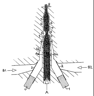
In fig. 1, the three components A, B1 and B2 are fed
into this characteristic part of the coextrusion die as
shown by the three arrows. This feeding is established by
primary, conventional feeding means (extruders or pumps),
CA 02403543 2004-12-17
9
which are not shown in the drawing. Between these
extruders or pumps and the apparatus shown there may be
conventional distribution means to ensure that the
components become evenly distributed over the width.
Normally A flows in steady manner (but may in some cases be
extruded in pulses) while B1 and B2 are extruded in pulses
established by rams (1), which superpose the flows produced
by the primary feeding means. The no-return valves (2)
which ensure that the rams work the right way can e.g. be
made of springy blades.
At the ports (3) where Bl and B2 enter the chamber for
A, there are two springy blades (4), which are extensions
of or connected with the wall (4a) of the chamber for A.
The blades (4) are installed as no-return valves. When
under a sufficient pressure from Bl and/or B2 they may even
act as shutters for A, so that after joining of the flows,
segments of A will alternate with segments of Bl + B2 (the
two may be of identical composition). However, this does
not take place in the embodiment of the invention shown in
the drawing. Here B1. and B2 are joined with A as "lumps"
(5) on each of its surfaces. Since the flows A, B1 and B2
are sheet-formed or ribbon formed and the shape of blade
(4) is adapted to this, these "lumps" will be transverse
"filaments" with their major direction perpendicular to the
view plane. The drawing shows the situation at the end of
the pulse, when the blades (4) are just about to close the
ports (3). Rams (1) are still pressing and the no-return
valves (2) therefore are closed. The previously coextruded
"lump" is shown as (6). In this application of the
invention, the apparent viscosities of B1 and B2 are
essentially lower than that of A, which will have the
' effect that the "lumps" gradually will be smeared or
sheared out to practically even layers while the B1-A-B2
= flow moves through the common passageway (7) towards the
exit (8) of the coextrusion die.
Therefore, (6) is shown smaller than (5) and there is
not shown any ~,lump,, further downstream.
CA 02403543 2004-12-17
-
Each of the rams (1) can extend over the full width of
the generally sheet formed or ribbon formed flows B1 and
B2, or there may preferably be a row of rams for Bi and one
for B2 (depending on the mechanical construction). However
5 it must hereby be ensured that there is established an even
pressure from side to side in each of the flows when they meet the port (3).
This is a matter of the dimensions of
the chambers for B1 and B2, the distance between the rams,
and the pressures of Bl and B2 during the process.
10 In case the rams (1) extend over the full width of
flow A, the inlet channels (4b) for B1 and B2 upstream of
the valves (2) should also extend so, but if there is
arranged rows of rams, each ram should preferably be fed
from a separate channel. Along the length of the flap
closure (4), the distance from this flap to the opposite
wall of channel 4b may need to be very short relative to
the length of flap (4) since otherwise this flap may be
bent excessively towards the opposite wall when the
pressure of Bi or B2 is at minimum and the pressure in A is
high.
In some cases, especially in connection with the
second aspect of the invention, in which the frequency of
the pulsations is generally not as high as in the first and
third aspect, it is possible to use only one pulsating,
narrow ram (1) for each of the B components, to serve the
entire width of the coextrusion, even when this width is
sizeable, provided there is arranged for an efficient
distribution between this ram and the port (3) where the
components merge.
The flow-sheet like sketches 2a and b indicate the
successive sections in suitable dies for circular
coextrusion according to the invention while the drawings
fig. 3a and b as already mentioned illustrate the preferred
corresponding distribution system for component A. This
starts with a branching-out system, which first has been
described in U.S. patent 2.820.249 in which patent it is
used in connection with coating of items by coextrusion.
CA 02403543 2004-12-17
11 _ -
Component A is fed into this system through port (10) ,
then branches out to two partflows in channels (11),
continues as 4 partflows in channel (12) and 8 partflows in
channels (13). (Depending on the dimensions of the die
there can of course be formed a bigger or smaller number of
partf lows but in any case a power of 2.) The part-flows in
(13) continue in a"spiral distribution system, through
grooves (14) whereby a proper balance is established by
rheological calculations between the flows through the
spiral grooves (14) and an over-flow between the latter,
which takes place in narrow gaps in the spaces (15) the
beginning of which are shown by the lines (16).
A similar branching-out system can conveniently be
used for components B1 and B2, however when there is used
a circular array of rams, as shown, and the latter are
sufficiently close together, there is no need for spiral
distribution of these components, since each of the part-
flows which result from the dividing out, then more
practically can go directly to a ram. Furthermore, if the
viscosities of Bl and B2 are much lower than that of A, a
lower degree of branching of these two components will be
sufficient
In practice, the distribution systems for A, which are
shown in figs. 3a and b, may be carried out in a die or
die-section consisting of two discs, which are screwed
together. The channels (grooves) may be formed in one of
these discs only, or preferably a part of each channel is
formed in one and another part in the other disc, with
these channel parts fitting together.
However, as mentioned in connection with fig. 1, one
ram for each B-component can under circumstances be
sufficient, but then an efficient distribution between this
ram and port (3) is needed.
As mentioned fig. 3a, which shows in detail fig. 2a's
"section for merging", is a modification of fig. 1. The
reference numbers have the same significance. It should be
CA 02403543 2004-12-17
12
noted that the springy blades (4) are plane like in fig. 1,
but now of course in the form of flat disc-formed rings.
Similarly, if the chambers for Bi and B2 immediately
upstream of the no-return valves (2) are circular chambers
around the entire die, as they can be, then the two valves
(2) are also formed as flat, disc-formed rings and can be
set-up in a system as here shown, - however as it appears
from the foregoing it is usually more practical to let each
of the part-flows which result from the dividing-out go
directly to a ram through a separate conduit, and in that
case an arrangement as that shown in fig. 1 is also
applicable.
As shown in the drawing, the circular die should
normally be adapted to extrude the composite flow Bl/A/B2
out in a generally axial direction when leaving the exit
(8).
The rams (1) can be operated by direct mechanical, by
hydraulic, pneumatic or electromagnetic means. Hydraulic
operation will normally be most convenient. In the inwardly
extruding system (fig. 2a) the rams are easily accessible
from the outside of the die, but in the outwardly extruding
system (fig. 2b) one array of rams must be operated through
the open bore in the middle of the die. This open bore can
also be used for other conduits or connections, e.g. a
conduit for internal cooling of the extruded tube.
Obviously the die set-up in which the flows move inwardly
(fig. 2a) is best suited for manufacture of tubular
sheeting or pipes of a relatively small diameter down to
10mm or less, while the other set-up (fig. 2b) is best when
a relatively large diameter of the product is wanted for
instance up to 5m or more.
When producing pipes in which stiff segments alternate with soft segments, the
set-up shown in fig. 2a should be
used.
The modifications shown in figures 4b, c and d can be
seen as modifications of the flat die shown in fig. 1 and
also as modifications of the circular die shown in fig. 3.
CA 02403543 2004-12-17
13
The modification shown in fig. 4a relates only to flat dies
(to fig. 1) since a flap closure becomes conical if it is
considered circular, and of course in that form it cannot
work.
The significant reduction of thickness of flow which
= appears from fig. 4a can be advantageous if there is a
particular need to reduce the back pressure in component A
and still under use of the lubricating effect of B1 and B2,
end with a relatively thin sheet.
Fig. 4a also illustrates the feature that the opening
and/or closing of the flap closure (4) can be effected
through mechanical transmission means (4c) instead of by
induced pressure variations in component B (or B1 and B2),
and furthermore f ig . 4a, as well as figs 4b-d, show the
flap closure (4) as a flexible blade ending in a thicker or
harder portion (4b) for the purpose of reinforcement and
stabilization. In fact this portion (4b) can be the main
part of the flap (4) while the shorter flexible part acts
as a hinge.
Going back to the mechanical transmission means (17)
in fig. 4a, they are here shown as rods which push on the
thicker or harder part (18) of the flap closure. When a
substantial pressure difference between component B (or
B1
and B2) and component A is required (see claim 11) then
obviously the. flap closure (4) must be adapted to withstand
this pressure difference and keep the port closed when not
mechanically activated. Alternatively, (17) can be hinged
on (18) and may act by pulling or push-pulling.
The different arrangements of the channels shown in
figs. 4b, c and d may be chosen in cases when there may be
constructional problems in arranging the flows of the A and
B components generally parallel with each other prior to
the merging. However, the abrupt bending of flows shown in
these sketches may under inappropriate circumstances cause
a harmful'stagnation.
In figs. 5a and b a generally dry particulate product
(A) which e.g. may be a raw material for ceramics, plastics
CA 02403543 2004-12-17
14
e.g. PTFE composites, foodstuff or medical pills, is fed by
gravity from a hopper through feeding chamber (17) into the
A-extrusion channel (18). The hopper is preferably
evacuated, since air can cause problems in the coextrusion,
blending and compacting processes.
In fig. 5a the upstream and downstream boundaries of
the feeding location is shown by the dash lines 19 and 20.
The feedin-g of A by gravity may be assisted by a vibrator
or by other agitation means (not shown). A is propelled
through the channe 1(18 ) by means of a ram (21). In the
most backward position of this ram, its front generally
coincides with the backward boundary of the feeding
location (dash line 19). Before moving ram (2i) forward to
propel A, the connection between the hopper and channel
(18) is closed by a gliding-closure (22) as indicated by
arrow (23).
Fluid components B1 and B2 (which normally are
identical) are coextruded in pulsations by means of the two
rams (1) through the Bi and B2 extrusion channels (4b) to
port (3) comprising the no-return valve (4), which is a
flap closure, all as explained in connection with fig. 1.
The movements of the three rams, one (21) for A and
two (1) for B. and B2, may be simple reciprocations, but
especially for Bl and B2 it will usually be advantageous to
work in series of forward strokes followed by a continuous
retraction to the starting position. Ram (21) is
preferably lubricated either with BI/B2 component or with
a fluid which for purposes which depend on the intended use
of the final product can be considered as compatible with
Bi and B2. This lubricant can be injected from behind the
ram or otherwise in well-known manner. Means for this are
not shown.
The lubricant should preferably be pumped into the
coextrusion system in amounts which are sufficient not only
for lubricating ram (21) but also for lubricating.the
propelled flow of A during its passage towards port (3).
CA 02403543 2004-12-17
The fluid B1 and B2 components, which are coextruded
on the two surfaces of the dry, particulate flow, may be
able to penetrate to the middle of flow A without any use
of mechanical blending means, but usually such means are
5 needed if a reasonably homogenous blending of A, B1 and B2
is wanted. In the drawing these means are the flaps (24),
which vibrate fast in mutually synchronized manner and
thereby subject the composite flow tb a shear which is
transverse to the main flow direction. Transmission rods
10 (24a) for these vibrations are shown.
The combined coextrusion and blending according to
this aspect of the invention is in particular advantageous
if the proportion between the fluid components (B1 and B2)
and the generally dry, particulate component (A) is
15 relatively low so that blended product on the whole still
appears particulate (as distinguished from a paste). When
the composite flow has this character, there may be a need
to compact the material before the exit from the extrusion
die. If only a slight compression is needed a narrowing of
conduit (7) may be sufficient, but the tendency of such
particulate products to block a narrowing passageway is
very high, and increased pressure on ram (21) may not
overcome such blocking. This problem is solved by carrying
out the compression transversely by means of fast vibrating
stamps (25), which are oppositely synchronized, so that
they alternately move towards and away from each other.
These stamps cover the full width of the composite flow,
and the front of at least one of them is biased in relation
to the main direction of the flow so that they gradually
reduce the gap of the conduit. In the position where the
stamps are closest together they should preferably be
slightly closer together than the gap of exit 8.
Instead of two stamps (25) there may be one only.
In this drawing the blending means (24) are shown as
flaps but can alternatively be stamps, (i.e. comprising a
component which mixes in a generally rectilinear
CA 02403543 2004-12-17
16
direction), and the means for compression are shown as
stamps but can alternatively be flaps.
In fig. Sa the surfaces of flaps (24) and the fronts
of stamps (25) are with some approximation generally
parallel with the surfaces of the
coextruded B1 and B2 layers. However this third aspect of
the invention can also be carried out in a way which will
appear if the apparatus part downstream of the dash line 26
is understood as turned 900 around an axis parallel with
the main direction of flow. In this way it will be
possible to make a composite extrusion device with several
exits (8) close together in array as required for the
"lamellar coextrusion" which has been mentioned above. The
"lamellar extrusion" using this embodiment of the invention
can e.g. be used as an improved method to make medical
pills which release the active substances in the body in
several steps at predetermined time intervals, a function
of pills which in itself is well-known.
Example
This example demonstrates the use of the invention for
manufacture of a novel confectionery product, which can be
expected to have good sales appeal, namely corrugated
(waved) chips of marzipan covered on both sides with thin
layers of dark chocolate. In the principle this could be
done by ordinary coextrusion, when the chocolate is in
semi-molten, high viscosity state with an apparent
viscosity reasonably close to the apparent viscosity of the
plastic marzipan mass. However, the melting range of the
dark chocolate is very narrow and the chocolate has~high
tendency to become supercooled and therefore remaining
truly fluid instead of becoming part-solidified, when it
gradually cools down from the molten state. This means that
it is very difficult to "tailormake" the rheology of the
dark chocolate for such a coextrusion. Therefore the
present invention is used,.and the chocolate is maintained
truly molten and fluid while it is coextruded with the
plastic marzipan mass.
CA 02403543 2004-12-17
17
The process is carried out in a pilot-coextrusion line
in which the die is constructed essentially as shown in
fig. 1, however the exit of the die, beginning where the
conduit (7) begins to narrow down, is gradually changed
into the corrugated shape, that is the sides of the slot
are parallel and have the shape of a wave, with the angle
at the midpoints being about 30 to the wave direction. The
gap of exit (8) is 2,5 mm, and the width of this and of the
corresponding channels in the die is 30 mm. The depth of
channel (7) before the narrowing is 4;0 mm, depth of
channel for A (marzipan) before the merging is 3,0 mm. The
depth of the two channels for component B (chocolate) is
2,0 mm at the beginning, but changes to 1,0 mm along the
blades (4). This low depth is chosen in order to secure
that the blades (4) do not bend in an irregular manner
under the pressure from component A. The length of the
blades (4) is 16 mm and thickness of the latter is 0,20 mm
over the first 5 mm and 0,40 mm over the rest. The length
of channel (7) before the narrowing is 100 mm.
A (marzipan) is constantly fed by means of a
conventional ram extruder, hydraulically driven, and B
(molten chocolate) is also primarily fed by means of a
conventional ram extruder (not shown), but in this case
pneumatically driven. The reason for driving the A-ram
hydraulically is the relatively high pressure required,
while the reason for driving the B-ram pneumatically,
partly is the lower pressure needed, and partly the need to
obtain a certain "buffer" effect, so that the pressure in
B upstream of the non-return valves (2) does not raise
excessively when these valves are closed.
Due to the very low width of the die in this pilot
= line, there is not used distribution means between these
primary rams and the dieparts shown in fig. 1.
Each of the (secondary) rams (1) immediately upstream
of the merging zone cover the full width of the flows.
Their pistons are of a rectangular section with cross-
sectional dimensions 29,95 mm x 1,95 mm. Their movements
CA 02403543 2004-12-17
18
are directly mechanically driven with adjustable strokes.
They perform a series of 10 strokes forward followed by
return to the starting position.
The temperature of B is kept at 40 C and the
temperature of A at 15 C until these components enter
the die. The reason for using this relatively low
temperature is to assist in the cooling of B.
The temperature of the die is maintained at 32 C,
under conditions of equilibrium the chocolate will be part
molten at this temperature, but under the actual conditions
of this extrusion it becomes supercooled and remains truly
fluid, except where it immediately contacts the cold
marzipan.
The pressure in the A-ram is adjusted to produce a
throughput of 15 g/s. Under actual conditions this
corresponds to about 50 bar (5 x 10⁶Pa). The primary B-ram
is extruding under a pressure of about 10 bar (1 x 10⁶Pa).
The secondary rams for B (1) work in strokes of about
0,05 sec duration with a period (stroke + interruption) of
0,1 sec corresponding to 10 strokes per second. The
amplitude of the strokes is adjusted to make a 0,4 mm
coating of chocolate on each side of the marzipan.
The corrugated "tape" of marzipan covered with
chocolate is relatively stiff when it leaves the exit (8)
of the die. It travels 2 mm unsupported and is then
conveyed by a belt. Cold air is blown for cooling. While
on the conveyor belt the "tape" is cut to short lengths.