Note: Descriptions are shown in the official language in which they were submitted.
CA 02403672 2002-09-20
WO 01/70137 PCT/USO1/09273
MIJLTIPIECE IMPLANTS
FORMED OF BONE MATERIAL
FIELD OF THE INVENTION
The invention relates to an implant for orthopedic applications. More
particularly, the invention is related to an implant formed from two or more
bone portions.
BACKGROUND OF THE INVENTION
Bone grafts have become an important and accepted means for treating bone
fractures and defects. In the United States alone, approximately half a
million bone grafting
procedures are performed annually, directed to a diverse array of medical
interventions for
complications such as fractures involving bone loss, injuries or other
conditions
necessitating immobilization by fusion (such as for the spine or joints), and
other bone
defects that may be present due to trauma, infection, or disease. Bone
grafting involves the
surgical transplantation of pieces of bone within the body, and generally is
effectuated
through the use of graft material acquired from a human source. This is
primarily due to
the limited applicability of xenografts, transplants from another species.
Orthopedic autografts or autogenous grafts involve source bone acquired
from the same individual that will receive the transplantation. Thus, this
type of transplant
moves bony material from one location in a body to another location in the
same body, and
has the advantage of producing minimal immunological complications. It is not
always
possible or even desirable to use an autograft. The acquisition of bone
material from the
body of a patient typically requires a separate operation from the
implantation procedure.
Furthermore, the removal of material, oftentimes involving the use of healthy
material from
the pelvic area or ribs, has the tendency to result in additional patient
discomfort during
rehabilitation, particularly at the location of the material removal. Grafts
formed from
synthetic material,have also been developed, but the difficulty in mimicl~ing
the properties
of bone limits the efficacy of these implants.
As a result of the challenges posed by autografts and synthetic grafts, many
orthopedic procedures alternatively involve the use of allografts, which are
bone grafts from
other human sources (normally cadavers). The bone grafts, for example, are
placed in a host
-I-
CA 02403672 2002-09-20
WO 01/70137 PCT/USO1/09273
bone and serve as the substructure for supporting new bone tissue growth from
the host
bone. The grafts are sculpted to assume a shape that is appropriate for
insertion at the
fracture or defect area, and often require fixation to that area as by screws
or pins. Due to
the availability of allograft source material, and the widespread acceptance
of this material
in the medical community, the use of allograft tissues is certain to expand in
the field of
musculoskeletal surgery.
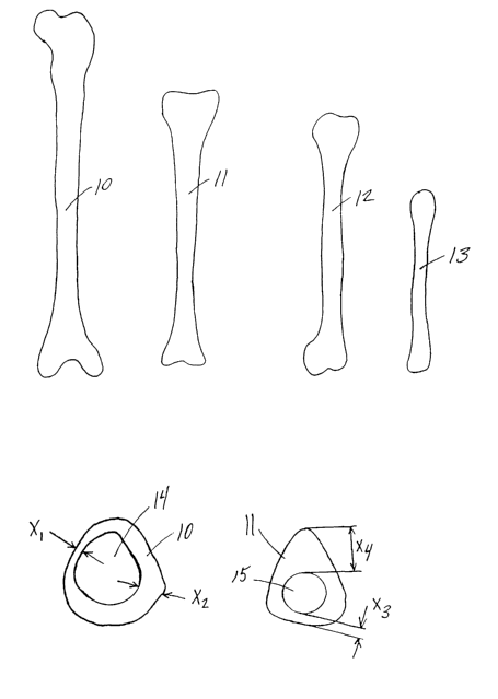
FIGS. 1A, 1B, 1C, and 1D show the relative sizes of the femur 10 (thigh),
tibia 11 (lower leg), humerus 12 (upper arm), and radius 13 (lower arm)
respectively for an
adult. As can be seen when comparing these bones, their geometry varies
considerably.
The lengths of these bones may have a range, for example, from 47 centimeters
(femur), to
26 centimeters (radius). In addition, as shown in FIGS. 1E and 1F, the shape
of the cross
section of each type of bone varies considerably, as does the shape of any
given bone over
its length. While the femur 10, as shown in FIG. 1E, has a generally rounded
outer shape,
the tibia 11 has a generally triangular outer shape as shown in FIG. 1F. The
wall thickness
also varies in different areas of the cross-section of each bone. For example,
femur 10 has a
wall thickness Xl that is much smaller than wall thickness Xz. Similarly,
tibia 11 has a wall
thickness X3 that is much smaller than wall thickness Xø. Even after clearing
the inner canal
regions 14 and 15 witlun the bones, the contours of these canals vary
considerably. Thus,
machining of the bone to have standardized outer dimensions and/or canal
dimensions is
necessary in many applications.
Sections of bones with regions having narrow cross-sections, as seen for
example with thicknesses Xl and X3, may be rejected for use in certain
applications because
the wall thickness does not have sufficient strength. Preferably, no region of
a bone section
has a thickness less than 5 millimeters, although in some applications smaller
wall
thicl~nesses may be employed. Thus, in the case that a bone section is found
to have a
region with a wall thickness less than a minimum acceptable thickness, such a
bone section
is rejected as being unsuitable for use in a bulb configuration. Often, such a
section is
ground into bone particulate that is then used in other applications. The
minimum thickness
standards imposed on the use of bone sections results in the rejection of
substantial
quantities of bone sections, and thus an inefficient use of the material. Bone
sections that do
not meet the minimum thickness standards are often found in older individuals.
As a collagen-rich and mineralized tissue, bone is composed of about forty
percent organic material (mainly collagen), with the remainder being inorganic
material
(mainly a near-hydroxyapatite composition resembling 3Ca3(P04)2 ~ Ca(OH)Z).
Structurally,
the collagen assumes a fibril formation, with hydroxyapatite crystals disposed
along the
length of the fibril, and the individual f brils are disposed parallel to each
other forming
-2-
CA 02403672 2002-09-20
WO 01/70137 PCT/USO1/09273
fibers. Depending on the type of bone, the fibrils are either interwoven, or
arranged in
lamellae that are disposed perpendicular to each other.
There is little doubt that bone tissues have a complex design, and there are
substantial variations in the properties of bone tissues with respect to the
type of bone (i.e.,
leg, arm, vertebra) as well as the overall structure of each type. For
example, when tested in
the longitudinal direction, leg and arm bones have a modulus of elasticity of
about I7 to I9
GPa, while vertebra tissue has a modulus of elasticity of less than 1 GPa. The
tensile
strength of leg and arm bones varies between about 120 MPa and about 150 MPa,
while
vertebra have a tensile strength of less than 4 MPa. Notably, the compressive
strength of
I0 bone varies, with the femur and hmnerus each having a maximum compressive
strength of
about I 67 MPa and 132 MPa respectively. Again, the vertebra have a far lower
compressive
strength of no more than about 10 MPa.
With respect to the overall structure of a given bone, the mechanical
properties vary throughout the bone. For example, a long bone (leg bone) such
as the femur
15 has both compact bone and spongy bone. Cortical bone, the compact and dense
bone that
surrounds the marrow cavity, is generally solid and thus carries the majority
of the load in
major bones. Cancellous bone, the spongy inner bone, is generally porous and
ductile, and
when compared to cortical bone is only about one-third to one-quarter as
dense, one-tenth to
one-twentieth as stiff, but five times as ductile. While cancellous bone has a
tensile strength
20 of about 10-20 MPa and a density of about 0.7, cortical bone has a tensile
strength of about
100-200 MPa and a density of about 2. Additionally, the strain to failure of
cancellous bone
is about 5-7%, while cortical bone can only withstand 1-3% strain before
failure. It should
also be noted that these mechanical characteristics may degrade as a result of
numerous
factors such as any chemical treatment applied to the bone material, and the
manner of
25 storage after removal but prior to implantation (i. e. cliying of the
bone).
Notably, implants of cancellous bone incorporate more readily with the
surrounding host bone, due to the superior osteoconductive nature of
cancellous bone as
compared to cortical bone. Furthermore, cancellous bone from different regions
of the body
is known to have a range of porosities. Thus, the design of an implant using
cancellous
30 bone may be tailored to specifically incorporate material of a desired
porosity
It is essential to recognize the distinctions in the types and properties of
bones when considering the design of implants. Surgeons often world with bones
using
similar tools as would be found in carpentry, adapted for use in the operating
room
environment. This suggests that bones have some properties which are similar
to some
35 types of wood, for example ease in sawing and drilling. Notably, however,
are many
differences from wood such as the abrasive nature of hydroxyapatite and the
poor response
-3-
CA 02403672 2002-09-20
WO 01/70137 PCT/USO1/09273
to local heating during machining of a bone. The combination of tensile and
compressive
strengths found in bone, resulting from the properties of the collagen and
hydroxyapatite, is
thus more aptly compared to the tensile and compressive strengths found in
reinforced
concrete, due to steel and cement. Furthermore, while wood is readily
available in
considerable quantity, bone material is an extremely limited resource that
must be used in an
extremely efficient manner.
Various types of bone grafts are known. For example, as disclosed in U.S.
Patent No. 5,989,289 to Coates et al., a spinal spacer includes a body formed
of a bone
composition such as cortical bone. The spacer has walls that define a chamber
that is sized
to receive an osteogenic composition to facilitate bone growth.
U.S. Patent No. 5,899,939 to Boyce et al. discloses a bone-derived implant
for load-supporting applications.. The implant has one or more layers of fully
mineralized or
partially demineralized cortical bone and, optionally, one or more layers of
some other
material. The layers constituting the implant are assembled into a unitary
structure, as by
joining layers to each other in edge-to-edge fashion in a manner analogous to
planking.
Another bone-grafting material is disclosed in U.S. Patent No. 4,678,470 to
Nashef et al., and is formed using a tanning procedure involving
glutaraldehyde that renders
the material osteoinvasive. A bone block is shaped into a precise
predetermined form and
size using conventional machining techniques. A paste-life suspension is also
formed using
known methods of comminuting bone, such as milling, grinding, and pulverizing,
and
adding the pulverized or powdered bone to a carrier. The treatment with
glutaraldehyde
allows the use of bovine, ovine, equine, and porcine bone sources. However, if
the final
desired form of the bone grafting material is a bloclc of bone or machined
shape, the bone
stock must be large enough to provide a block of the required size.
U.S. Patent No. 5,981,828 to Nelson et al. discloses a "composite" acetabular
allograft cup for use in hip replacement surgery. A press is used to form the
cup from
impacted cancellous bone chips and cement. The composite is a hollow
hemispherical dome
having an outer surface comprised essentially of exposed cancellous bone chips
and an inner
surface comprised essentially of hardened bone cement. The cancellous bone
chips are first
placed in a mold and subjected to a load to form a compact and consolidated
mass that
conforms to the shape of the mold. The mold is then opened, cement is applied,
and the
mold is then reapplied. While an allograft of a particular shape may be formed
using this
process, the process is limited to forming an allograft by compressing
cancellous bone chips.
Thus, numerous molds are required in order to produce allografts of different
sizes, and the
use of bulk-size allograft source material is not facilitated.
-4-
CA 02403672 2002-09-20
WO 01/70137 PCT/USO1/09273
With a rapidly increasing demand in the medical profession for devices
incorporating bone material, the tremendous need for the tissue material
itself, particularly
allograft tissue material, presents a considerable challenge to the industry
that supplies the
material. Due to the size and shape of the bones from which the material is
harvested, and
the dimensional limitations of any particular type of bone in terms of
naturally occurring
length and thickness (i. e. cortical or cancellous), there is a need for a
means by which
individual bone fragments can be combined to form larger, integral implants
that are more
suitable for use in areas of larger fractures or defects. For example, the
size of cortical bone
fragments needed to repair a fracture or defect site is often not available in
a thick enough
form. While multiple fragments may together meet the size and shape
requirements, several
prominent concerns have placed a practical limitation on the implementation of
this concept.
There is considerable uncertainty regarding the structural integrity provided
by fragments
positioned adjacent to one another without bonding or other means of securing
the
fragments to each other. Moreover, there is concern over the possibility that
a fragment may
slip out of position, resulting in migration of the fragment and possible
further damage in or
near the area of implantation.
In addition, due to the geometry of bones such as the femur and tibia, all
portions of the bones are not readily usable as a result of size limitations.
Thus, prior art
implants, specifically allografts, are produced with an inefficient use of
source bones.
There is a need for new, fundamental approaches to working with and
processing tissues, in particular allograft material, especially with regard
to machining,
mating, and assembling bone fragments. Specifically, there is a need for an
implant that
allows more efficient use of source material. More specifically, there is a
need for an
implant that is an integrated implant comprising two or more bone fragments
that are
interlocked to form a mechanically effective, strong unit.
SUMMARY OF THE INVENTION
The present invention is related to an implant including a body having an
inner sheath and at least one outer sheath. Each sheath is formed from a
different bone and
has an interior surface and an exterior surface. The exterior surface of each
outer sheath
contacts the interior surface of no more than one other outer sheath. In one
embodiment, a
core is disposed in the inner sheath and is formed from a bone other than the
bones of the
sheaths. The core can be formed of cancellous bone, while at least one sheath
can be formed
of cortical bone. In another embodiment, at Ieast one sheath can be formed of
cancellous
bone and the core can be formed of cortical bone. The bones are at least one
of autograft,
allograft, and xenograft bone tissue, and the bone tissue of at least one bone
may be partially
-5-
CA 02403672 2002-09-20
WO 01/70137 PCT/USO1/09273
demineralized or demineralized. In a further embodiment, the body is formed
from a cross-
section of the sheaths and core, with the cross-section including at least a
portion of each
sheath and core. The sheaths and core can be coupled together with at least
one fastener that
may intersect each of the sheaths and core, with the fastener being a screw,
key, pin, peg,
rivet, cotter, nail, spike, bolt, stud, staple, boss, clamp, clip, dowel,
stake, hook, anchor, tie,
band, crimp, or wedge. Also, the sheaths and core can be bonded together with
a bonding
agent. At least one sheath may be packed with bone growth materials and may
include
alignment indicia. The exterior surface may be separated from a portion of the
interior
surface.
At least one of the inner sheath, an outer sheath, and the core can be at
least
partially dehydrated to fit against a surrounding mating surface. Furthermore,
at least one of
the inner sheath, an outer sheath, and the core can be at least partially
dehydrated to fit
within a surrounding inner sheath or outer sheath provided with a greater
moisture content.
Contacting surfaces of adjacent sheaths can be machined surfaces so that the
contour of the contacting surfaces is about the same. The machined surfaces
permit press-
fitting of one sheath into another sheath. In some embodiments, the bones are
selected from
a femur, tibia, humerus, fibula, ulna, and radius.
At least one supplemental sheath having an interior surface and an exterior
surface also may be included, with the exterior surface of each supplemental
sheath
contacting the interior surface of no more than one other sheath and the
interior surface of
each supplemental sheath contacting the exterior surface of no more than one
other sheath.
The at least one supplemental sheath is formed of a material selected from
metals, alloys,
ceramics, polymers, and composites.
The present invention is also related to an implant having a body formed
from a cross-section of a core and a plurality of sheaths. Each sheath has an
inner surface
and an outer surface, and at least two sheaths are formed from different
bones. The outer
surface of a first sheath has about the same contour as the inner surface of a
second sheath so
that the first and second sheaths mate together, and the cross-section
includes at least a
portion of each sheath and core. The core may be formed from a bone other than
the bones
of the sheaths, and in one embodiment the core is formed of cancellous bone
and at least one
sheath is formed of cortical bone. In another embodiment, at least one sheath
is formed of
cancellous bone and the core is formed of cortical bone.
Also, the present invention is related to an implant with a body that includes
at least one sheath defining a hole, with a core fit therein. The body is
formed from at least
two different bones selected from a femur, tibia, humerus, fibula, ulna, and
radius.
-6-
CA 02403672 2002-09-20
WO 01/70137 PCT/USO1/09273
Furthermore, the present invention is related to an implant with a body
having two outer annular members and at least one inner annular member. At
least one of
the annular members is formed from bone and the annular members are coupled
together to
create a central chamber. In one embodiment, each annular member has at least
one surface
that is press-fit with the surface of another annular member. The outside
diameter of the
outer annular members may be smaller than the outside diameter of the at least
one inner
annular member. The implant can be symmetrical about an innermost annular
member, with
the diameter of the implant progressively decreasing from the innermost
annular member to
each outer annular member. The central chamber can be pacl~ed with at least
one of bone
material and bone inducing substances.
In one embodiment, at least one annular member is formed of cancellous
bone and at least one annular member is formed of cortical bone. A plurality
of ammlar
members may be coupled together with at least one fastener. Also, a plurality
of annular
members may be bonded together with a bonding agent. In some embodiments, the
annular
members have non-circular shapes, such as generally oblong shapes. At least
one
supplemental annular member may be coupled to at least one of the annular
members
formed from bone, with the at least one supplemental annular member being
formed of a
material selected from metals, alloys, ceramics, polymers, and composites. At
least one
annular member rnay include alignment indicia, and adjacent surfaces of at
least two annular
members may not completely contact each other.
The invention further relates to an implant with a body having at least two
ring-shaped members formed from bone that axe coupled together to create a
central
chamber. The ring-shaped members may have ridges that mate and press-fit
together.
Another implant of the present invention includes at least two layers of bone
components coupled to each other, the components together defining at least
one securing
region, and at least one insertable securing element adapted for placement in
the at Ieast one
securing region. The at least one securing region may be a recess or hole, and
each layer
may be formed from a different bone selected from a femur, tibia, humerus,
fibula, ulna, and
radius. At least one layer may be formed of cancellous bone and at least one
layer may be
formed of cortical bone. Also, the layers may include at least one of
autograft, allograft, and
xenograft bone tissue, and the layers may be bonded together with a bonding
agent. The
bone tissue of at least one bone may be partially demineralized or
demineralized, and the
layers may be bonded together with a bonding agent. A first layer may be at
least partially
dehydrated to mate against at least one other layer. Adjacent layers may be
provided with
mutually contacting surfaces that are machined to have about the same contour,
and the
contacting surfaces of adjacent layers may be press-fit together.
CA 02403672 2002-09-20
WO 01/70137 PCT/USO1/09273
In addition, the implant may further include at least one supplemental layer
coupled to at least one of the layers of bone components, with the at least
one supplemental
layer being formed of a material selected from metals, alloys, ceramics,
polymers, and
composites. Also, the implant may further include a chamber packed with bone
growth
materials. In some embodiments, at least one layer includes alignment indicia,
and the outer
surface may be separated from a portion of the inner surface.
The present invention is further related to a hollow body having a minimum
wall thickness, the body being formed from a plurality of portions of bone
sections with
each section having a thick-walled portion and a thin-walled portion. The
thick-walled
portion has a wall thickness at least as thiclc as the minimum wall thickness,
and the thin-
walled section has a wall thickness less than the minimum wall thickness. Only
thick-
walled portions are coupled together to form the body. The thick-walled
portions are
coupled together with at least one portion having a first coupling and at
least one portion
having a second coupling, with the portions being joined together by
interfitting together the
first and second couplings. At least one coupling may be at least partially
'dehydrated to
mate against smother coupling. In one embodiment, the first coupling is a male
coupling and
the second coupling is a female coupling so that the portions are mated in a
male-female
relationship. The male coupling maybe a tenon and the female coupling may be a
mortise,
or the male coupling may be a tongue and the female coupling may be a groove.
The present invention is also related to an implant including a layer formed
of a first bone and at least one layer formed by a curable carrier, with the
at least one layer
being molded to the first bone. The layer formed of a first bone may include a
primary
sleeve with a top surface, a bottom surface, an inner surface, and an outer
surface, with the
at least one layer of curable carrier being molded to the inner surface or the
outer surface. In
one embodiment, the curable carrier further includes bone or ceramic in
powder, chips, or
fibers. At least one secondary sleeve may be provided, with each secondary
sleeve being
coupled to a primary sleeve or another secondary sleeve by a layer of curable
carrier.
Additionally, the present invention is related to a method of forming an
implant including: surrounding at least a portion of a bone section with a
first mold to create
a cavity therebetween; filling the cavity with a first substance, and coupling
the first
substance to the bone section. The first substance may be at least one of a
curable Garner,
bone powder, bone chips bone fibers, or ceramic, and be coupled to the bone
section by
curing or by compaction.
-g_
CA 02403672 2002-09-20
WO 01/70137 PCT/USO1/09273
BRIEF DESCRIPTION OF THE DRAWINGS
Preferred features of the present invention are disclosed in the accompanying
drawings, wherein similar reference characters denote similar elements
throughout the
several views, and wherein:
FIGS. 1A to 1D show prior art exemplar bone sizes and shapes for bones
from an adult human;
FIGS. lE-1F show prior art exemplar bone sections having varying wall
thickness, the sections taken transverse to the longitudinal axis of the
bones;
FIGS. 1G to 1I show perspective views of bone portions that may be
combined to form an embodiment of an implant of the present development;
FIGS. 1J to 1K show perspective views of another embodiment of the present
development combining multiple bone sections;
FIG. 2A shows a perspective view of the embodiment of FIG. 1K with
section lines;
FIG. 2B shows a perspective view of the section of the embodiment of FIG.
1K forming an implant;
FIG. 2C shows a side view of the implant of FIG. 2B;
FIG. 2D shows an exploded view of the implant of FIG. 2B;
FIGS. 3A to 3C show perspective views of sections of a tibia and femur
combined in another embodiment of the present invention;
FIG. 3D shows a top view of the embodiment of FIG. 3C;
FIGS. 4A to 4D show top views of yet another embodiment of the present
invention combining sections of bone having acceptable wall thiclmess with
mating joints;
FIGS. 4E to 4G show exploded, perspective views of another embodiment of
the present invention combining sections of bone having acceptable wall
thicl~ness with
mating joints;
FIGS. 5A to SE show perspective views of additional embodiments of the
present invention combining multiple bone sections;
FIG. SF shows an exploded, perspective view of another embodiment of the
present invention combining multiple bone sections;
FIG. 6A shows a top view of another embodiment of the present invention
forming a femoral ring implant;
FIG. 6B shows a side view of the implant of FIG. 6A;
FIG. 6C shows a cross-section of the implant of FIG. 6A taken along line
VIC-VIC;
-9-
CA 02403672 2002-09-20
WO 01/70137 PCT/USO1/09273
FIG. 6D shows a cross-section of the implant of FIG. 6A taken along line
VID-VID;
FIG. 7A shows perspective views of concentric rings formed of bone material
for coupling to form an implant;
FIG. 7B shows a side view of an embodiment of the present invention with
an implant formed from the concentric rings of FIG. 7A;
FIG. 7C shows an exploded, perspective view of the implant of FIG. 7B;
FIGS. 8A and 8B show exploded, side views of another embodiment of the
present invention forming a spacer;
FIGS. 8C and 8D show additional side views, respectively, of bone pieces of
the spacer of FIGS. 8A and 8B;
FIG. 8E shows a side view of the teeth used in the spacer of FIGS. 8A and
8B;
FIGS. 9A to 9C show exploded, perspective views of additional
embodiments of the present invention using washer-shaped bone portions;
FIG. 10 shows a top view of an additional embodiment of an implant
according to the present invention with bowed bone portions;
FIG. 11 shows a perspective view of an additional embodiment of an implant
according to the present invention with press fitting of bone portions in two
locations;
FIG. 12 shows an exploded, perspective view of an additional embodiment of
an implant according to the present invention with bone portions that mate;
FIG. 13 shows a top view of an additional embodiment of a multilayer
implant according to the present invention;
FIG. 14 shows an exploded, perspective view of the implant of FIG. 13;
FIG. 15 shows a perspective view of an embodiment of the present invention
formed with a cancellous body and cortical struts;
FIG. 16 shows an exploded, perspective view of an additional embodiment of
the present invention formed with a cancellous body and cortical struts;
FIG. 17 shows an exploded, perspective view of an additional embodiment of
the present invention formed with a combination of cancellous and cortical
bone;
FIG. I8 shows a perspective view of an additional embodiment of the present
invention formed with a combination of cancellous and cortical bone; and
FIGS. 19A and 19B show perspective views of the formation of a composite
implant by molding.
-10-
CA 02403672 2002-09-20
WO 01/70137 PCT/USO1/09273
DETAILED DESCRIPTION OF THE PREFERRED EMBODIMENTS
Any of a wide variety of different implant structures, particularly allograft,
autograft, and/or xenograft implant structures, can be prepared according to
the teachings of
the present invention. While a representative selection of implant structures
are described
and depicted herein, additional disclosure is found in U.S. Provisional
Application No.
60/191,099 filed March 22, 2000, which is hereby incorporated herein in its
entirety by
reference, including all figures.
The present invention allows a more efficient use of bone sections, by
permitting those sections that would otherwise have been rejected due to
insufficient wall
thiclcness to instead be incorporated in a composite bone section. The
composite implant is
created by taking two or more bone sections and combining them to create a
greater wall
thiclcness. Some or all of the natural shape of each bone may be retained.
Furthermore, the
composite may be formed of a shape appropriate for implantation, or instead
may be formed
of a shape that is suitable as bone stock for eventual fashioning into a
particular implant or
forms.
As used in the description of the present invention, the words fitting,
interfitting, mating, locking, interlocking, meshing, and interlacing are all
used generically
to describe the joining of bone sections or pieces together. Thus, these words
are not limited
to the use of any particular manner of joining. Thus, for example, the press-f
tting of one
bone section within a cavity formed in another bone section may be described
using any of
the above-mentioned terms. In addition, although various preferred mechanical
fastening
approaches are described, the present invention allows the use of any
mechanical device for
joining two or more separate parts of an article or structure. Such mechanical
devices
include, but are not limited to the following: screws, lceys, pins, pegs,
rivets, cotters, nails,
spilces, bolts, studs, staples, bosses, clamps, clips, dowels, stakes, hooks,
anchors, ties,
bands, and crimps. Also, bonding agents or other chemical means for joining
two separate
parts may be employed alone or in combination with the mechanical devices.
Thus, as
appropriate, the means disclosed herein for fixing bone sections to each other
may be
substituted, as with the above-mentioned mechanical devices, bonding devices,
or chemical
means. Furthermore, although particular types of joints are disclosed, the
present invention
is directed to the creation of implants that may be joined using other joints.
While the present invention is preferably directed to the creation of implants
from allograft material, the present invention may also be applied to implants
that utilize
other materials, including but not limited to the following: xenograft,
autograft, metals,
alloys, ceramics, polymers, composites, and encapsulated fluids or gels.
Furthermore, the
implants described herein may be formed of materials with varying levels of
porosity, such
-11-
CA 02403672 2002-09-20
WO 01/70137 PCT/USO1/09273
as by combined bone sections from different bones or different types of tissue
having
varying levels of porosity. For example, cancellous bone is available in a
range of porosities
based on the location in the body from which the bone is harvested. Extremely
porous
cancellous bone may be harvested from various areas such as the iliac crest,
while less
porous bone may be harvested from areas such as a tibial condyle. Thus, the
materials
properties - particularly the porosity - of the bone components may be
selected to meet the
needs of a given application.
Cancellous bone components may be attached to syringes or aspirators, and
blood or other fluids such as bone-growth inducing substances may be drawn
into the plugs.
The use of mechanically applied pressure, such as with aspiration devices,
permits a greater
degree of fluid absorption and/or concentration to be achieved than otherwise
readily
obtainable by soaking bone in such fluids without applying pressure from a
device. In
embodiments of the present invention that include hollow regions, a plug of
cancellous bone
formed using the aforementioned technique may be inserted therein.
Alternatively, the
plugs may be soaked in a suitable fluid.
Also, the implants described herein may be formed of bone materials with
varying mineral content. For example, cancellous or cortical bone may be
provided in
natural, partially demineralized, or demineralized states. Demineralization is
typically
achieved with a variety of chemical processing techniques, including the use
of an acid such
as hydrochloric acid, chelating agents, electrolysis or other treatments. The
demineralization treatment removes the minerals contained in the natural bone,
leaving
collagen fibers with bone growth factors including bone morphogenic protein
(BMP).
Variation in the mechanical properties of bone sections is obtainable through
demineralization. Advantageously, use of a demineralizing agent on natural
bone
transforms the properties of the bone from a stiff structure to a relatively
pliable structure
when it is hydrated. Some portions of interfitting bone components may be
demineralized
in order to achieve improved interfitting. For example, a tissue form may
include two bone
components having portions that are coupled together with an interference fit.
The
interference fit may be enhanced if the surface region of one or more of the
components is~
demineralized so that it is pliable and exhibits some elasticity and/or
malleability.
In addition, while many of the embodiments described herein show bone
components disposed at right angles, or joints formed with right angles,
angles that are
greater or less than ninety degrees may alternatively be used in implants of
the present
development.
3S FIG. 1G shows a first embodiment of implant 16 having an outer sheath 17,
an intermediary sheath 18, and a core 19. It should be noted that while bone
sections
- 12-
CA 02403672 2002-09-20
WO 01/70137 PCT/USO1/09273
described herein are referred to as sleeves, these components need not be
cylindrical or
otherwise symmetrical. In this embodiment, outer sheath 17 is a bone section,
for example
of a femur, that has the outer surface or contour naturally found on a femur.
Thus, the outer
surface 20 of outer sheath 17 does not require machining and is not machined.
The inner
surface 21 of outer sheath 17 has been machined to a particular configuration
so that
intermediary sheath 18 fits within outer sheath 17. Alternatively, as shown in
FIG. IH,
implant 16 may have a through hole 22 instead of a core 19, creating a cavity
in implant 16. .
If a through-hole is provided instead of core 19, a hollow implant may be
created and bone
growth materials such as bone materials in the form of chips, slurries, or
fibers, as well as
bone inducing substances can be provided therein. While the cavity may be
formed from
sleeves with two open free ends, such a hollow region may also be created by
incorporating
one or more sleeves with one free end closed. It should be noted that two or
more sections
of bone are used to create the composite, and thus there is no limit to the
number of sheaths
or bone sections that may be combined. Typically, insert or core 19 is
cylindrical in shape,
as shown in FIG. 1I, and may be made of cancellous bone while each surrounding
sheath
may be made of cortical bone. Alternating layers of cortical and cancellous
bone may be
used, or several layers of the same type of bone may be used along with a
different type of
bone.
The components that are used to create implant 16 may all be formed from
cortical bone, all from cancellous bone, or a combination of components formed
from
cortical and cancellous bone. The interfitting of the components may be
achieved through a
variety of means, including but not limited to the following: pinning, bonding
with a
suitable bone bonding agent or chemical means, press fitting, threadably
engaging (as by
helically screwing one component into another), inserting a tapered component
into a
component with a matching inner surface, twist-loclcing, or other interlocking
means such as
will be described in other embodiments. While the present development
preferably allows
the creation of an implant 16 from all bone material, it is also anticipated
that one or more
components used to create implant 16 may be formed of non-bone material such
as a
synthetic or other material.
As shown in FIG. 1J, in a second embodiment of the present invention many
types of bones may be combined in layers to form bone stock 25'. A radius 13
may be
encased in humerus sleeve 12, which may be encased in tibia sleeve 11, which
may further
be encased in femur sleeve 10 that retains the original outer shape of the
femur. In alternate
embodiments, other bones may be used, such as a fibula or ulna. By machining
the inner
~.~or outer surfaces of each bone section, the bone sections may be inserted
into each other
-13-
CA 02403672 2002-09-20
WO 01/70137 PCT/USO1/09273
with an interfitting relationship. This may result in a strong press-fit, but
additional or
alternate means of fixation may be employed, such as mechanical means.
The moisture content of the bone sections also may be varied to
advantageously permit improved interlocking. Bone sections initially may be
provided with
moisture content as follows: (1) bone in the natural state fresh out of the
donor without
freezing, (2) bone in the frozen state, typically at -40°C, with
moisture content intact, (3)
bone with moisture removed such as freeze-dried bone, and (4) bone in the
hydrated state,
such as when submersed in water. The expansion and contraction properties that
can be
obtained from bone during heating, cooling, dehydrating, and hydrating permit
an alternate
approach to achieving a tight press-fit. In addition, the use of such
approaches can provide a
tighter press-fit than otherwise obtainable, as well as loosen the
manufacturing tolerances
required for mating sections of bone.
For example, in the embodiment shown in FIG. 1J, sleeve 12 is initially
supplied with a first outer diameter and a first inner diameter. Subsequent
freeze-drying of
sleeve 12 results in shrinkage such that sleeve 12 assumes a configuration
with a second
outer diameter that is smaller than the first outer diameter, while having a
second inner
diameter that is smaller than the first inner diameter. When sleeve 12 is
rehydrated or
treated with a swelling agent, sleeve 12 may reassume a configuration with the
first outer
diameter and first inner diameter. By providing a bone section such as a
sleeve 12 in the
freeze-dried state while disposed inside another bone section such as sleeve
11 that may be
loosely interference fit, rehydration of sleeve 12 in place permits a tighter
interference fit to
be achieved. Notably, a bone section such as core 13 has no inner diameter,
and thus such a
bone section may shrinl~ in outer diameter only when freeze-dried. Thus,
similarly, core 13
may be the bone section that is rehydrated to provide a tighter mating and
interference fit
with a sleeve 12. Use of these properties can permit greater variation in
dimensional
tolerance between bone sections during manufacture, while tight final assembly
can still be
achieved. In addition, protrusions on bone sections become smaller when
dehydrated, but
expand when rehydrated; in contrast, recesses in bone sections become smaller
when
hydrated, but larger when dehydrated. Temperature changes may also be used to
achieve
better interference fits.
Turning to FIGS. 1J-K, a hole 23 of similar dimension may be created in
each bone section, and when the holes are aligned to be coaxial, a pin 24 may
be inserted in
the holes 23 for fixation. Alternatively, the bone sections may have a slot
formed
therethrough, similar in orientation to pin 24, and a lcey can be inserted or
press-fitted into
the slot to fix the sections with respect to each other. Other bones may also
be used, for
example an ulna (lower arm) is similar in configuration to radius 13, and thus
may be
- 14-
CA 02403672 2002-09-20
WO 01/70137 PCT/USO1/09273
readily substituted. In addition, a fibula can also be readily used in some
embodiments,
accounting for the size of the bone and any required machining. Also, although
the
embodiment shown in FIGS. 1J and 1K show bones with generally cylindrical
shapes, other
shapes can be used, for example by machining the bones to have a rectangular
shape or any
other shape.
Bone stock 25' is preferably solid, and formed by fitting a smaller diameter
bone core within at least one larger diameter sheath. Thus, the availability
of precisely
'machined cores and sheaths permits bone stock 25' to be sized according to
the application
or anatomy encountered in any given situation. In addition, implants may be
constructed
1 p from a supply of standardized core and sheath sizes or bone stock sizes so
that any required
wall thickness can be obtained. The ability to create composite implants of
varying sizes
has widespread use, particularly in applications such as femoral ring
allbgrafts which can
benefit from increased wall thicknesses.
In alternate embodiments of bone stock 25', components having non-circular
15 shape may be provided, although not necessarily the natural shape of the
original bone. For
example, an outer sheath can mate with an inner sheath which has a generally
triangular
shape, with the inside surface of the outer sheath geometrically conforming to
the outside
surface of inner sheath. Other polygonal shapes are also contemplated,
including
parallelograms such as rectangles. In addition, a core may be provided with a
shape distinct
20 from both the cylindrical outside surface of the outer sheath and the
outside surface of the
inner sheath. Thus, the present development permits components with varying
outside
surface shapes to be interfit to create an implant.
The availability of larger bone stock, as by combining several bone sections,
makes it possible to create implants that are properly configured for
implantation during a
25 wide variety of procedures. For example, anterior interbody fusion is a
surgical procedure
which replaces some or all of a disc with a bony graft (implant) by using an
anterior
approach to the disc. Such a procedure is typically employed in the cervical
spine, and
implantation of an implant is an effective modality for the treatment of such
conditions as
degenerative disc disease and herniated nucleus pulposus (slipped disc).
Anterior interbody
30 fusion is also used in the lumbar spine in cases of unsuccessful posterior
approaches, or in
procedures directed to destroyed or damaged facet joints, procedures that
combine posterior
instrumentation with an anterior discectomy (i.e. removal of herniated disc
material from the
spinal canal so that the spinal cord or nerve is restored to an unpinched
state) and fusion
(which allows vertebrae to effectively be knit together into a solid bony
mass), along with
35 other procedures that cannot employ a posterior approach. Thus, the
implants may also be
employed in anterior discectomy and fusion, which involves the removal of an
intervertebral
-15-
CA 02403672 2002-09-20
WO 01/70137 PCT/USO1/09273
disc and the replacement of that disc with an implant that will undergo
fusion, both steps
being undertaken via an anterior approach. Other surgical procedures employing
the
anterior approach, including procedures used in fusing the thoracic region,
may also make
use of the implants.
Alternatively, surgical procedures involving a posterior approach may also
employ the implants created using the current invention. For example,
posterior lumbar
interbody fusion, another surgical technique used for spinal fusion, involves
the posterior
insertion of an implant into the intervertebral space following posterior
excision of a disc
through the spinal canal.
Bone stoclc 25' as shown in FIGS. 1J and 1K may be sectioned, for example,
as shown in FIGS. ZA-2D, along axes 43 and 44, resulting in a cross-section
slice 45 of bone
stock 25' having a thickness XS as shown in perspective view in FIG. 2B and in
side view in
FIG. 2C. In this embodiment, a pair of pins 24 instead is used to retain the
pieces of bones
10, 11, 12, and 13 in engagement. Pins 24 may be oriented at an angle with
respect to each
other, as shown in FIG. 2C, such that they are nonpere11e1, thereby resisting
separation of the
bone pieces. Alternatively, the pieces of bone may be keyed (not shown) for
additional
interlocking. Such composite bone stock may be used, for example, to create an
implant
suitable for posterior lumbar interbody fusion. Optionally, in order to
prevent migration of
such an implant when placed in an anatomical region, serrated regions in the
form of saw
teeth 24' may be provided on the periphery of slice 45. Although slice 45
includes a core 13
that is fully surrounded by sleeve 12, as shown for example in the exploded
view of slice 45
in FIG. 2D, alternate embodiments of a slice of bone stock 25' do not
completely surround
core 13.
While bone stock 25' utilizes four separate bone pieces, other numbers of
pieces are contemplated. For example, a core may be surrounded by only two
sleeves to
produce a desired stock size. Also, pins 24 may be formed from bone.
Another composite implant is shown in FIGS. 3A-3D. In this embodiment, a
section of a femur 46 has a inner surface 47. Preferably, in order to increase
the wall
thickness of section 46, this bone section may be used as a sleeve that
surrounds a portion of
a tibia section 48. Although the tibia naturally has a generally triangular
shape, a portion 49
of the tibia 48 may be machined to have an outer geometry that mates with
inner surface 47
of femur 46. A canal 50 may remain in the composite implant, or it may be
filled with
another bone or other material. By inserting portion 49 within sleeve 46, a
protruding
section 52 remains on tibia section 48. Such a section may be cut off, for
example along
axis 51, so that section 52 may be used for another purpose, such as serving
as bone material
for use in other implants.
-16-
CA 02403672 2002-09-20
WO 01/70137 PCT/USO1/09273
Yet another approach to maximizing the use of a bone sections with thin wall
areas is shown in FIGS. 4A to 4D. In this embodiment, a femur section 53 is
cut with a
tongue and groove pattern, creating a portion 54 having an acceptable wall
thickness and a
portion 55 with an unacceptable wall thickness. A similar cut is performed on
another
femur section, and the portion 55 from the second femur section may be removed
and
matched with the portion 54 from the first femur section. Thus, a composite
implant is
created with consistently thick and acceptable wall thickness. Portion 53 may
be used for
another purpose. In addition to matching tongues 56 and grooves 57 formed in
sections 55
and 54, respectively, other matching geometrical shapes such as matching
notches 58 may
also be provided as shown in FIG. 4E. Other suitable configurations of
interlocl~ing
portions include interlocking teeth 59 formed in matching sections 54' and
55', as shown in
FIGS. 4F and 4G. In an alternate embodiment, a synthetic portion may be
matched with a
bone portion to create a composite implant with appropriate wall thickness,
and may be
formed of other materials such as metals, polymers, or ceramics.
FIGS. 5A to 5C show implants created by joining three components. Implant
60 has two outer portions 61 and 62 that surround the cylindrical surface 63
of core 64.
Outer portions 61 and 62 are joined to each other using pins 65 and 66 (shown
in phantom),
and core 64 is press fit or otherwise secured between portions 61 and 62. In
the embodiment
shown in FIG. 5A, portions 61 and 62 have mating surfaces defined at areas 67
and 68 that
do not interfit. Alternatively, as shown in FIG. 5B, implant 69 has two outer
portions 70
and 71 that interfit and surround a core 64. Portion 70 has a tongue portion
72 that fits in a
groove in portion 71. Likewise, portion 7I is also provided with a tongue
portion 73 that
fits in a groove in portion 70. Notably, designs employing tongue and groove
configurations have a significantly increased mating surface area, thereby
providing a
greater surface over which joining can be achieved with concomitantly greater
strength.
Interfitting may also be achieved using the design of implant 74 shown in
FIG. 5C. Portion 75 has protruding portions 76 and 77 that each are partially
formed with
outside surface 78, while portion 79 has protruding portions 80 and 82 that
interfit with
protrusions 76 and 77. As shown in FIG. 5D, implant 84 may instead include a
combination
of tongue portions 86 and 88 that fit within grooves disposed in opposing
outer portions,
protruding portions 90 and 92, as well as mating surfaces 94 and 96. Implant
98 uses
dovetail joints 100 to secure outer portions 102 and 104. The dovetail joint
is particularly
useful because it resists pullout, although sliding may still occur along axis
106. The
dovetails provide a positive lock transverse to axis 106 so that pullout can
be prevented, and
such an interlocking arrangement of components generally resists the
separation of the bone
components from each other. As with the tongue and groove design, the use of a
dovetail
-17-
CA 02403672 2002-09-20
WO 01/70137 PCT/USO1/09273
joint creates a greater surface area for bonding. Although implant 98 is shown
with only
one dovetail on each outer sheath portion, additional dovetails may be
provided.
Additionally, the present development allows the joining of more than two
outer portions.
Thus, instead of two halves, three or more outer portions may be joined.
Furthermore, the
core may be of any desired shape, as may be the outside surface of the outer
portions.
Portions of the implants, such as portions 75 and 79, may be formed of
different materials,
for example cortical bone, cancellous bone, and ceramic materials.
Numerous types of joints are useful in the present development, including
joints that permit articulation such as a ball and soclcet type of joint, and
particularly joints
that permit firm interlocking between two components to prevent relative
movement
between the components. Preferably, mortise and tenon joints can be used to
interfit
multiple bone components to create an implant as shown for example in FIG. SF.
Bone
component 122, shown in exemplary form with a rectangular shape, contains a
rectangular
mortise or cavity 124. Bone component 126, also rectangular in overall
configuration,
includes a rectangular-shaped tenon 128 that is inserted in cavity 124 to
thereby form a joint.
The size and shape of tenon 128 is closely matched to that of cavity 124. Once
components
122 and 126 are joined, as shown by arrow A, an implant or larger bone stock
is created.
The mortise may be partial or extend through the component, and a tenon sloped
haunch
portion may be provided on the tenon for interfitting with a mortise sloped
haunch portion
on the mortise. Other forms of the mortise and tenon joints are also
appropriate, as are other
coupling arrangements such as edge joints including tongue and groove joints,
rabbeted
joints, toothed joints, and dovetail joints.
The use of insertable securing elements such as keys, pegs, pins, wedges, or
other suitable components in joints to assist in securing bone components to
each other is
also an effective approach to providing a stable joint. Keys, for example,
rnay be inserted in
notched or grooved areas in bone components, serving as the securing element
between two
or more bone components. Parameters that may be varied when using insertable
securing
elements, such as keys, include the angle of application, the spacing of the
elements, and the
thicknesses of the elements.
Refernng to FIGS. 6A-6D, a femoral ring implant 200 is shown for use in
anterior lumbar interbody fusion, and is formed of several layers of bone in
the form of
sleeves. In the preferred embodiment, a sleeve 202 formed from a femur or
tibia has another
sleeve 204 formed from a humerus inserted therein. The sleeves 202, 204 may be
press-fit,
pinned, keyed, and/or joined by other means. Although implant 200 is shown
with a central
chamber 206, which may be left empty or filled with bone materials or other
bone inducing
substances, in alternate embodiments central chamber 206 may be filled with
another bone
-18-
CA 02403672 2002-09-20
WO 01/70137 PCT/USO1/09273
portion to create a solid implant. A cancellous plug, for example, may be
placed in central
chamber 206. Combinations of cortical or cancellous bone may be used, and
additional
sleeves may also be provided. Saw teeth 208 or other protrusions may be
provided on the
periphery of implant 200 to anchor the implant in the desired anatomical
region. Implant
$ 200 is formed in a generally l~idney-shaped configuration to conform to the
natural anatomy
of vertebral bodies encountered during anterior lumbar interbody fusion.
Alignment indicia 210 may be provided on the outer surface of implant 200,
as with a line or other aid. Preferably, indicia 210 is an imprint, z. e. with
ink, although
indicia 210 may instead be provided in the form of surface scoring. The
indicia suitable for
the present invention includes, but is not limited to, markers such as lines,
arrows, lettering,
and symbols. In addition, alignment indicia 2I0 preferably is provided on the
anterior side
of implant 200 to aid in aligiunent with the natural anatomy encountered
during surgery, and
particularly to aid in alignment with the anterior longitudinal ligament (ALL)
that extends
over the length of the lumbar spine anterior to the vertebral bodies. In
particular, the ALL
may be used as a landmark in combination with alignment indicia 210, for
example, to
permit a surgeon to properly align implant 200 with respect to surrounding
anatomy.
Refernng to FIGS. 7A to 7C, interlocking concentric circular bone
components may also be created from bone stoclc. For example, concentric bone
portions
1020, 1022, 1024, 1026, and 1028 may be combined to form an implant. Some of
the
concentric circular components may be provided with two portions, each having
a different
outer diameter such as portion 1047 and ridge 1048. Ridge 1048 has an outer
diameter that
is slightly smaller than the inner diameter of ridge 1049, thus allowing ridge
1048 of a first
component to be press fit into the ridge 1049 of a second component. This
permits implants
of varying sizes to be created by interlocking several bone components
together, for
example to create implant 1050. Side and exploded, perspective views of
implant 1050 are
shown in FIGS. 7B and 7C respectively. Keys may also be inserted into the
walls of
assembled bone components to provide further interlocking of the concentric
cylinders.
Furthermore, once assembled and secured to each other, the annular members may
be cut to
create other appropriate shapes. Implant 1050 utilizes bone portions that are
formed from
the natural size and overall geometry of particular bones, so that available
bone material
may be used efficiently. For example, bone portions 1020, 1028 may be formed
from a
radius, bone portions 1022, 1026 may be formed from a humerus, and bone
portion 1024
may be formed from a femur. Although implant 1050 is shown with concentric
circular
portions, is other embodiments non-circular, ring-shaped bone components may
also be
similarly provided such as oblong arcuate forms like elliptical shapes, or
polygonal shapes.
-19-
CA 02403672 2002-09-20
WO 01/70137 PCT/USO1/09273
In some embodiments, caps are optionally provided in the outermost concentric
circle bone
portions to form a completely-enclosed chamber within implant 1050.
Turning to FIGS. 8A-E, another spacer implant 1100 according to the present
invention is shown. Two bone pieces 1102,1104 are provided with mating
portions 1107,
1108 respectively. Once interfitted, bone pieces 1102, 1104 provide a multi-
layer, oval-
shaped implant structure with a central hole 1112, which may be packed with
bone-growth
inducing substances. Preferably, one or more of the outer surfaces on implant
1100, such as
outer surface 1106, is provided with teeth 1110. In a preferred embodiment,
teeth 1110 are
pyramidal in shape with edges formed at an angle ~i of about 60°.
Preferably, at least a
potion of an inner surface of a bone piece 1102, 1104 is provided with a
protrusion that is
received in an opposing groove. For example, as shown in FIGS. 8A and 8B, bone
piece
1102 is provided with an inner surface that includes a groove 1118 for mating
with a
symmetrically formed protrusion 1116 on bone piece 1104. Centering lines 1114,
1116 may
also be provided on implant 1100 to assist in the orientation and overall
placement of
implant 1100 in the body. Although the implant 1100 of FIGS. 8A-E is formed of
two
layers of bone, implants of more than two layers of interfitting bone are
contemplated.
Referring to FIGS. 9A-C, various other configurations of bone portions may
be provided. For example, an implant 1200 may be formed with interfitting
washer 1202
and base 1204 bone pieces. Alternatively, an implant 1220 may be formed with
multiple
washer-lilce pieces 1222, 1224 that interfit with a core 1226. In addition, an
implant 1240
may be formed with washer-like pieces 1242, 1244, an intermediate piece 1246,
and a core
1248 that extends the length of all pieces 1242, 1244, 1246. The mating
surfaces of the
components of these embodiments may be fixed to each other using any of the
aforementioned means such as pins and adhesives. In addition, different types
of bone may
be selected for the components of these embodiments. In one embodiment,
implant 1200
includes a cancellous ring 1202 and a cortical base 1204. In another
embodiment, implant
1240 includes cortical washer-like pieces 1242, 1244, a cancellous
intermediate piece 1246,
and a cortical core 1248.
Another embodiment according to the present invention is shown in FIG. 10.
Implant 1260 is formed with bowed bone portions 1262, 1266. Bone portion 1262
is
provided with grooved regions 1264, while bone portion 1266 is provided with
protrusions
1268 that mate with grooved regions 1264.
Yet another embodiment of an implant 1280 is shown in FIG. 11. An outer
bone portion 1282 surrounds an inner bone portion 1284. Advantageously, inner
bone
portion 1284 only contacts outer bone portion 1282 along two small regions
1286, 1288
along the length of portions 1282, 1284. Thus, in this embodiment a press-fit
of bone
-20-
CA 02403672 2002-09-20
WO 01/70137 PCT/USO1/09273
portions 1282, 1284 is only provided at regions 1286, 1288. Such a
construction permits
outer bone portion 1282 to deflect with respect to inner bone portion 1284.
Such a
construction facilitates press-fitting of outer and inner bone portions.
Closely mating outer
and inner bone portions may be difficult to press-fit due to the tightness
inherent in the fit
itself and the dimensions of the bone portions. A less tight fit, as provided
for example by
implant 1280, may permit a press-fit to be achieved with less difficulty. In
sum, an implant
1280 with an inner bone portion 1284 of oblong or slightly elliptical geometry
can provide
an acceptable interference fit, while facilitating assembly without as much
concern for
breakage. While a press-fit with two points or regions of contact has been
described, it is
also contemplated that press-fits with more than two points or regions of
contact may be
used.
Further embodiments of multipiece implants are shown in FIGS. 12-14.
Referring to FIG. 12, implant 1300 is formed of bone portions 1310, 1312, and
1314. Bone
portion 1310 includes a central hole or recess 1316 with a diameter D1, while
bone portion
1312 includes a prong 1320 with a diameter D2 and a central hole or recess
1318 with a
diameter D3. Diameters D1, DZ are chosen such that bone portions 1310 and 1312
mate at
hole 1316 and prong 1320, and preferably a press-fit is achieved. Similarly,
bone portion
1314 includes a prong 1322 with a diameter D4 and a central hole or recess
1324. Diameters
D3, D4 are chosen such that bone portions 1312 and 1314 mate at hole 1318 and
prong 1322,
and preferably a press-fit is achieved. In the embodiment shown, diameters D2,
D4 are
chosen to be different. Thus, if an implant requires a central cancellous bone
portion 1312
between cortical bone portions 1310, 1314, the proper construction is more
likely to be
achieved due to the specific interfitting relationships of the bone portions.
As shown in FIGS. 13-14, a mufti-layer implant 1330 includes a core bone
portion 1332 surromded by bone portions 1334, 1336, 1338, 1340. The shape of
core bone
portion 1332 serves as a lcey for orienting and mating with bone portions
1334, 1336, and
similarly bone portions 1334, 1336 together serve as a key for orienting and
mating with
bone portions 1338, 1340. Any number of bone portions may be aligned with
respect to
each other using this key configuration.
Refernng now to FIGS. 15-16, the use of cortical bone struts to confer
additional structural strength to implants is shown. For example, implant 1350
of FIG. 15
includes a cancellous body 1352 with holes 1353 formed therein. Cortical
struts 1354 are
inserted in holes 1353 to improve the strength of implant 1350. In particular,
because
cancellous bone does not provide significant structural strength, cortical
struts with higher
structural strength, particularly in compression, are used. Advantageously,
implant 1350 is
formed in part from an osteoconductive material, the cancellous bone, to
facilitate
-21-
CA 02403672 2002-09-20
WO 01/70137 PCT/USO1/09273
incorporation of the implant into surrounding bone tissue. Implant 1350 may be
formed of
bone that is demineralized, partially demineralized, or with natural mineral
content, and may
be formed from other shapes. Holes 1353 and struts 1354 may have other cross-
sections
such as triangular or rectangular shapes, and similarly body 1352 may be
another shape. A
central hole 1355 also may be included and additional materials may be packed
or molded
therein. Turning to FIG. 16, an exploded view of an implant 1360 is shown.
Implant 1360
includes cortical end caps 1362, 1364 disposed on opposing sides of body 1368.
Cortical
struts 1366 extend through holes 1370 in body 1368 to improve structural
integrity of the
implant. One or both of end caps 1362, 1364 may include holes or recesses,
such as holes
1372 as shown in end cap 1364, to receive portions of struts 1366. The struts
may be press-
fit within holes 1370, 1372. Cortical end caps 1362, 1364 also serve to
distribute loading on
implant 1360.
Additional embodiments of implants with combinations of cortical and
cancellous bone are shown in FIGS. 17-18. Implant 1380 includes opposing
cortical caps
1382 each with heads 1384 and protrusions 1386. Cancellous body 1390 includes
opposing
recesses or holes 1390, which receive protrusions 1386 of caps 1382. Implant
1392 includes
cortical shells 1394, 1396 with a cancellous body 1398 disposed therebetween.
A central
region 1399 may be empty, filled with a plug of bone material such as
cancellous bone, or
filled with other materials.
Implants may be formed from composites of bone material and material that
is molded thereto. For example, femur section 46 shown in FIG. 3A has an inner
surface 47
that conforms to the natural shape of the femur bone canal. The wall thickness
of femur 46
varies, and may be increased using several approaches. As shown in FIGS. 19A
and 19B, a
molding apparatus 1400 may be used to produce an implant 1410 with desired
wall
thickness. A mold 1402 or object of smaller dimension than the hole 1404
defined by inner
surface 47 of femur section 46, and a curable liquid, slurry, paste, or gel
such as bone
cement, a viscous polymer, or a ceramic slurry can be poured between mold 1402
and inner
surface 47 and allowed to set in place. Alternatively, or in addition, a mold
1406 with a
larger dimension than femur section 46 may be placed around it. The wall
thickness of
femur section 46 may be increased by pouring bone cement between mold 1406 and
outer
surface 1408, so that the bone cement extends from the top surface 1407 to the
bottom
surface 1409. In alternate embodiments, the bone cement may not extend to top
surface
1407.
Once the bone cement has set, molds 1402, 1406 may be removed, leaving a
tissue form 1410 with a composite wall of the original femur section 46 and
bone cement
sections 1412, 1414. Other filler materials can be used with molds 1402, 1406,
such as a
-22-
CA 02403672 2002-09-20
WO 01/70137 PCT/USO1/09273
mixture of hydroxyapatite and cement that sets in place. In alternate
embodiments,
materials are molded only to portions of bone sections, instead of being
molded to
completely surround inner and/or outer surfaces of bone sections. Additional
molds can be
used for surrounding adjacent bone sections in implants formed with multiple
pieces of
bone, thereby permitting multiple bone sections to be coupled together with an
intermediary
layer of bone cement.
Molded sections such as sections 1412, 1414 may include mixtures or
suspensions of cancellous and/or cortical bone powder, bone chips, and bone
fibers, in
natural or demineralized conditions, in combination with bonding agents such
as bone
cements, water, fat, blood, thrombin, and fibrin. The fibers, in particular,
may be oriented to
provide particular mechanical properties. Fox example, fibers may be oriented
generally
parallel to axis 1416, transverse to axis 1416, or in mixed orientations in
order to achieve
desired strength when encased in bone cement that is cured. Other materials
also may be
combined with bonding agents or other carriers, such as hydroxyapatite.
Furthermore,
sections 1412, 1414 may additionally be formed by applying pressure while
curing occurs.
Alternatively, compactable powders and/or fibers of various sizes and shapes
may be pressed and compacted in place, without bonding agents or with minimal
use
thereof. Such pressed structures may be further encapsulated in thin layers of
bone cements
or polymers such as biodegradable polymers. While loose powder of varying
particle sizes
may be compressed and densified to produce a compact of the powder, it is
difficult to apply
uniform pressures while producing the compact. The so-called "single action"
pressing
technique, which typically applies a force to the powder in a single
direction, may be used in
the present invention. However, in some embodiments, because it is desirable
to produce a
compact with a more uniform density throughout the structure, other pressing
techniques
may be used.
Furthermore, the components of the implants described herein may be
formed by molding various materials onto support structures such as meshes or
other
structures that are lcnown to one spilled in the art. For example, titanium
mesh indicated for
reinforcement of bony regions in orthopedic procedures is typically available
in preformed
round and oval-shaped cylinders. The metal mesh may be encapsulated or
otherwise
surrounded by another material such as bone powder or bone fiber impregnated
bone cement
that has dried in place around the mesh. Multiple bone components may be
interfitted
together and further encapsulated or otherwise surrounded by molded materials
for
additional reinforcement. Also, molded material may be used to further couple
two or more
pieces of bone together. For example, a polymer such as polymethylmethacrylate
may be
placed in the central chamber of an implant and allowed to cure in place.
- 23 -
CA 02403672 2002-09-20
WO 01/70137 PCT/USO1/09273
While various descriptions of the present invention are described above, it
should be understood that the various features can be used singly or in any
combination
thereof. The various types of joints and connections can be used on bone
implants or bone
stock of different size or configuration, such that the invention is not to be
limited to only
the specifically preferred embodiments depicted in the drawings.
Further, it should be understood that variations and modifications within the
spirit and scope of the invention may occur to those slcilled in the art to
which the invention
pertains. For example, multiple, differently shaped and sized bone portions
can be
constructed for interfitting or interconnection to form a multiple part bone
implant that
serves the desired purpose. Accordingly, all expedient modifications readily
attainable by
one versed in the art from the disclosure set forth herein are within the
scope and spirit of
the present invention and are to be included as further embodiments. The scope
of the
present invention is accordingly defined as set forth in the appended claims.
20
30
-24-