Note: Descriptions are shown in the official language in which they were submitted.
CA 02403712 2002-09-18
WO 01/80801 PCT/USO1/13455
ABSORBENT SHEET MATERIAL HAVING CUT-RESISTANT PARTICLES AND
METHODS FOR MAHING THE SAME
TECHNICAL FIELD
The present invention relates generally to sheet materials which are cut-
resistant, shred-
resistant, and absorbent, and methods for making the same. More specifically,
in one
embodiment, the present invention relates to high basis weight paper
structures which include
randomly distributed polymer particles locked into the paper structure.
BACKGROUND OF THE INVENTION
Protective materials having durability, such as cut-resistance and/or wear-
resistance have
been used for many applications. For instance, protective materials can be
used as cutting boards
to cover countertops during food preparation, such as when cutting meats or
vegetables for
cooking. Such protective materials can protect the food item from contacting
contaminants which
may reside on the support surface, such as a countertop. In addition, such a
material can also
protect the support surface from physical damage from a cutting tool, as well
as from
contamination from the food item being prepared.
However, many materials which are protective are not absorbent. For instance,
a rigid
plastic cutting board will not absorb juices from food items, and these juices
may run off the
cutting board and soil the countertop or support surface. In addition, many
such materials are not
flexible, and thus are not easily stored, manipulated, and disposed. Also,
because many rigid
cutting boards are not intended to be disposed after use, they require
cleaning after each use.
On the other hand, many materials, such as paper-like materials, can exhibit
high
absorbency and flexibility and are disposable. However, such materials
typically lose a
significant amount of strength when wet, and thus cannot adequately protect a
support surface
from cutting forces. Also, such materials are not typically shred-resistant
and thus, if used as a
cutting board, particles from the material may transfer to the food item being
prepared.
Accordingly, many materials which are highly cut and shred resistant are
typically
undesirable for use as disposable cutting sheets, due to the low flexibility
and low absorbency
typically inherent in such materials, as well as the high cost of such
materials. Conversely, many
materials which are highly flexible or absorbent and of lower cost, are
typically undesirable for
use in such applications due to the low cut and shred resistance inherent in
such materials. For
instance, plastic materials are high in cut and shred resistance but low in
absorbency, while
CA 02403712 2002-09-18
WO 01/80801 PCT/USO1/13455
conventional paper materials are typically high in absorbency but low in cut
and/or shred
resistance, since paper fibers can be easily released as a cutting tool is
drawn over the cutting
surface.
Polymeric fibers have previously been utilized as a binder and strengthening
agent in
paper structures. Typically, in such paper structures, fibers made from
hydrophobic polymers are
added to paper fluff during paper formation. During drying of the mixture, the
polymeric fibers
flow and coat the surrounding paper fibers locking the paper fibers into the
structure and
significantly reducing the overall absorbency of the resulting structure.
While the amount of
polymer fiber could be reduced from the mixture to increase absorbency, such a
solution
compromises the cut-resistance and shred-resistance of the structure. Thus,
one problem with
such structures is that the amount of polymer fibers required to achieve
adequate cut-resistance
and/or shred-resistance significantly reduces the absorbency of the structure.
Accordingly, it is desirable to provide a sheet material which exhibits good
absorbency
and also good cut and shred resistance. It is also desirable to provide such a
material that is also
relatively flexible so as to be readily disposable, and easily dispensed,
stored, and manipulated.
In addition, it is desirable to provide such sheet materials which, while
durable in use, can be
economically manufactured so as to justify their disposal after each use.
SUMMARY OF THE INVENTION
It is an object of the present invention to obviate the above-described
problems.
Another object of the present invention is to provide a disposable and
protective cutting
sheet.
It is a further object of the present invention to provide a sheet material
that is absorbent,
cut-resistant and shred-resistant.
Yet another object of the present invention is to provide a sheet material
that can be used
to slice food items, and which can effectively absorb juice from the food
items while
simultaneously resisting damage from a cutting tool.
A further object of the present invention is to provide a sheet material that
is resistant to
shredding and can absorb significant amounts of fluid produced by food items.
Another object of the present invention is to provide a cut-resistant,
absorbent, shred-
resistant sheet material that is readily disposable.
Yet another object of the present invention is to manufacture a cut-resistant,
absorbent,
shred-resistant sheet material using conventional equipment.
2
CA 02403712 2002-09-18
WO 01/80801 PCT/USO1/13455
To achieve the foregoing and other objectives, and in accordance with one
aspect of the
invention, a cut-resistant, shred-resistant, and absorbent sheet material is
provided. The sheet
material comprises at least 50 percent by weight of an absorbent material. A
plurality of cut-
resistant particles that have an average size of at least about 100
micrometers are distributed
throughout the absorbent material. The sheet material preferably has a basis
weight of at least 100
pounds per 3000 ftz. It is also preferred that the absorbent material is
substantially free of
inorganic particulate filler.
According to another aspect of the invention, a method of forming a cut-
resistant, shred-
resistant, and absorbent sheet material is provided. The method comprises the
steps of forming a
mixture comprising absorbent fibers, non-fibrous polymeric particles, and
water. The polymeric
particles have an average size of between about 100 and about 1000
micrometers, the absorbent
fibers are provided in an amount of at least 50 percent by weight, and the
mixture is substantially
free of inorganic filler particulate. The mixture is formed into a sheet which
is then dried. The
dried sheet has a basis weight of at least 100 pounds per 3000 ftz.
Preferably, the sheet is
densified using heat and pressure to lock in the polymer particles and to
improve cut and shred
resistance.
According to another aspect of the invention, an absorbent and shred-resistant
sheet
material is provided comprising an absorbent substrate and cut-resistant
particles dispersed
through the absorbent substrate. The sheet exhibits a wet abrasion loss of
less than about 400 mg
per 100 revolutions and an absorbent efficiency of at least 0.2. It is
preferred that the cut-resistant
particles have an average size of at least about 100 micrometers. It is also
preferred that the sheet
has a basis weight of at least 100 pounds per 3000 ftz, that the absorbent
substrate is provided in
an amount of at least 50 percent by weight, and that the absorbent substrate
is substantially free of
inorganic particulate filler. Preferably, the sheet material exhibits a cut
resistance of at least 30
kgf/cm.
Still other objects of the present invention will become apparent to those
skilled in the art
from the following description wherein there is shown and described preferred
embodiments of
this invention, including a best mode currently contemplated for carrying out
this invention,
simply for the purposes of illustration. As will be realized, the invention is
capable of other
different aspects and embodiments without departing from the scope of the
invention.
Accordingly, the drawings and descriptions are illustrative in nature and not
restrictive in nature.
BRIEF DESCRIPTION OF THE DRAWINGS
CA 02403712 2002-09-18
WO 01/80801 PCT/USO1/13455
While the specification concludes with claims particularly pointing out and
distinctly
claiming the invention, it is believed that the same will be better understood
from the following
description of preferred embodiments, taken in conjunction with the
accompanying drawings in
which:
FIG. 1 is a plan view of an exemplary sheet of material, made according to
principles of
the present invention;
FIG. 2 is a cross-sectional view of the exemplary sheet material of FIG. 1;
FIG. 3 is a cross-sectional view of an embodiment of a layered sheet material,
made
according to principles of the present invention;
FIG. 4 is a cross-sectional view of a further embodiment of a layered sheet
material made
in accordance with the present invention;
FIG. 5 is a cross-sectional view of another embodiment of a layered sheet
material made
in accordance with the present invention;
FIG. 6 is a cross-sectional view of a further embodiment of a layered sheet
material made
in accordance with the present invention;
FIG. 7 is a cross-sectional view of a yet another embodiment of a layered
sheet material
made in accordance with the present invention;
FIG. 8 is a cross-sectional view of a further embodiment of a sheet material
made in
accordance with the present invention;
FIG. 9 is a general schematic illustration of a sheet processing system
suitable for
manufacturing the sheet material of FIG. 1 in accordance with principles of
the present invention;
FIG. 10 is a general schematic illustration of an alternative sheet processing
system
suitable for manufacturing the sheet material of FIG. 1 according to
principles of the present
invention;
FIG. 11 is a cross-sectional view of another embodiment of a sheet material
made in
accordance with the present invention;
FIG. 12 is a cross-sectional view of another embodiment of a layered sheet
material made
according to principles of the present invention;
FIG. 13 is a schematic diagram illustrating a process and related equipment
that can be
used for manufacturing the layered sheet material of FIG. 12;
FIG. 14 is a schematic diagram illustrating exemplary equipment and a process
that can
be used to densify sheet material, such as the sheet materials of FIGS. 2-8
and 11-12,; and
4
CA 02403712 2002-09-18
WO 01/80801 PCT/USO1/13455
FIG. 15 is a data table illustrating preferred properties of sheet materials
made in
accordance with principles of the present invention.
DETAILED DESCRIPTION OF PREFERRED EMBODIMENTS
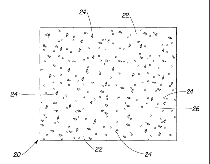
Turning now to the drawings in detail, wherein like numerals indicate
corresponding
structure throughout the views, FIG. 1 is a plan view of an exemplary sheet
material 20 made
according to principles of the present invention. In this embodiment, the
sheet material 20
includes an absorbent substrate 22 and a plurality of cut-resistant particles
24 randomly dispersed
throughout the substrate 22. As best shown in the cross-sectional view of FIG.
2, the sheet 20 is
of a substantially uniform thickness t, and includes a cutting surface 26 and
a second surface 28.
Preferably, the surfaces 26 and 28 are substantially planar.
The continuous absorbent substrate 22 may be formed from any material or
materials
suitable for absorbing and/or containing fluids of interest. For example,
suitable materials include
materials formed from natural fibers, such as cellulosic fibers or refined
cellulosic fibers, and/or
synthetic fibers, including hollow fibers and capillary channel fibers. As an
alternative to or in
combination with such fibers, the absorbent substrate 22 could include an
absorbent polymeric
foam material, an absorbent polymeric gelling material, a hydrogel material,
and/or natural
starches and gums, for example. Materials of particular interest include
cellulosic substrates, such
as paperboard, such as are typically used in paper manufacturing. As described
in further detail
below, SSK (Southern Softwood Kraft), NSK (Northern Softwood Kraft), or
eucalyptus cellulosic
fiber fluff could be used to form the substrate 22. The substrate 22 could
alternatively comprise a
non-woven substrate, such as can be constructed by entangling synthetic fibers
for instance.
In the embodiment of FIG. 1, the absorbent substrate 22 comprises a continuous
layer of
material. However, the substrate 22 could comprise a laminate structure having
a plurality of
layers of the same or differing composition. Moreover, the absorbent substrate
22 may comprise
an absorbent or non-absorbent carrier web that may include an absorbent
material.
The cut-resistant particles 24 may be formed from any durable material or
materials
which are substantially resistant to cutting, abrasions, and shredding from
cutting utensils used for
food preparation, such as kitchen knives for instance. Typical materials which
exhibit such
properties may be utilized, including those which exhibit a high degree of
toughness and a
crystalline molecular structure. In the preferred embodiment, the cut-
resistant particles 24 are
made from polymeric materials, such as ethylene vinyl acetate (EVA), high
density polyethylene
(HDPE), low density polyethylene (LDPE), linear low density polyethylene
(LLDPE), polyvinyl
CA 02403712 2005-02-25
chloride (PVC), plastisols, polypropylene (PP), polyethylene teraphthalate
glycol modified
(PETG), ultra high molecular weight polyethylene (UHMWPE), polystyrene, and/or
polyurethanes. Other thernnoplastics, thermosets, polyolefins, polymeric
and/or glass composite
materials can also be used. Furthermore, the particles 24 may include melamine
formaldehyde
polymers or polymeric materials compounded with fillers and/or additives, such
as talc, mica,
calcium carbonate, and/or other inorganic fillers.
Preferably, the material utilized for the cut-resistant particles 24 has a low
enough melting
temperature Tm such that it will soften at temperatures which will not cause
the substrate 22 to
char or burn during the application of heat. Such a material can thereby be
partially bonded to the
substrate 22 through the application of heat and/or pressure, preferably
during a subsequent
process which densifies the sheet material produced during an initial sheet
making process. Such
a process can also increase the cut resistance and shred resistance of the
sheet material. It is
preferred that the melting temperature of the particles be less than or equal
to about 450° F.
Preferably, the material used for the particles 24 has a Vicat softening point
(using ASTM test
D1525) of less than about 185° F, to allow it to more readily lock or
bond to the substrate 22
under relatively low or moderate temperature. One preferred material for use
in the particles 24 is
the polymer "PETG", such as, for example, is sold under the tradename EASTAR~"
PETG
COPOLYESTER 6763 by EASTMAN CHEMICAL CO, and which has a Vicat softening point
of around 185° F. Such a material has a good cut and shred resistance
and also has a relatively
moderate softening point to allow it to be more readily locked into the
substrate 22 through heat
and/or pressure, without charring or burning the substrate. Moreover, PETG is
less hydrophobic
than many other thermoplastics, and so the sheet 20 thereby maintains good
overall absorbency.
Another preferred material for use in the particles 24 is polystyrene.
As noted above, the particles 24 could also comprise compounded polymeric
materials.
For example, tough inorganic fillers can also be provided in combination with
one or more
polymers to form the particles 24, in order to reduce the cost of the
particles 24 and/or change
particle toughness, density, cut-resistance, color, or other property.
Suitable fillers include
CaC03, talc, and mica, for example. However, although particulates and fillers
can be used to
form particles 24, it is preferred that absorbent substrate 22 is
substantially free of inorganic free
filler particulate. As used herein, the term "free filler particulate" refers
to inorganic particles
which are not bonded to the absorbent substrate 22 and which merely reside
freely within the
absorbent substrate. Such a material may be released from the sheet 20 during
cutting operations
and be mixed with the food items being prepared, potentially making the food
undesirable in
6
CA 02403712 2002-09-18
WO 01/80801 PCT/USO1/13455
appearance and/or unsuitable for consumption. It is also preferable that the
absorbent substrate 22
is substantially free of organic free filler particulate which is not suitable
for contact with food
items. Organic free filler particulate does not refer to the absorbent
substrate material, such as
cellulosic fibers and the like as described herein. By "substantially free"
what is meant is an
amount no greater than that which would be safe for use of the absorbent
substrate in food
preparation, or less than an amount in which the filler particulate released
during food preparation
is noticeable by visual or tactile inspection of the absorbent substrate or
food items, or both. By
tactile inspection, what is meant is tactile sensory via the hand, or, with
respect to food items, the
mouth. Preferably, 0% of such free filler particulate is added to the
substrate. If free filler
particulate is included, however, the level should preferably be no greater
than about 10%, more
preferably no greater than about 5%, more preferably no greater than about 2%,
more preferably
no greater than about 1%, more preferably no greater than about 0.5%, and most
preferably no
greater than about 0.1% by weight of the dry sheet. Notwithstanding the above,
the sheet hereof
can be substantially free of free filler particulate if it contains unbonded
particulate material, but
none of the particulate material is releasable when the absorbent sheet is
used as intended (i:e., by
placing a food item on the side of the sheet intended to be used for cutting,
and cutting the food
item while it is on this side of the sheet.) Thus, the sheet can be
substantially free of filler
particulate when it includes unbonded particulate material which is positioned
or configured such
that little or none is released from the cutting surface during cutting. In
particular, it is preferred
that at least the cutting surface of the sheet material is shred resistant and
exhibits a wet abrasion
loss (according to the test described below) of less than about 400 mg per 100
revolutions, and
more preferably less than about 300 mg per 100 revolutions. In addition, it is
also preferred that
the cutting surface of the sheet material exhibits a dry abrasion loss
(according to the test
described below) of less than about 300 mg per 100 revolutions, and more
preferably less than
about 200 mg per 100 revolutions.
Because of the absorbent material or materials used in the substrate 22, the
sheet material
20 can absorb and sequester fluids deposited on the surfaces 26 and 28.
Moreover, because
relatively large polymer particles 24 are preferably used, rather than smaller
polymer fibers which
can coat the materials of the substrate 22 during formation of the final
sheet, much of the
absorbency of the substrate 22 is maintained. In other words, the polymer
particles 24 do not
completely cover or surround materials of the substrate 22, and therefore do
not significantly
mask their absorbent properties. Accordingly, more polymer 24 can be provided
in the sheet 20
without significantly impacting the absorbency of the sheet. In contrast, the
same amount of
7
CA 02403712 2002-09-18
WO 01/80801 PCT/USO1/13455
small polymer fiber has been found to completely disperse through the
structure and surround the
material of the substrate 20 and lock out much of its absorbency.
In this regard, it is preferred that the polymeric particles 24 are provided
in amounts of up
to about 50 percent by weight of the sheet 20. More preferably, the particles
24 are provided in
amounts of between about 10 percent and about 40 percent by weight, and most
preferably in an
amount of around 30 percent by weight. It is also preferred that the absorbent
material within
the sheet 20 is provided in amounts of at least 50 percent by weight, in order
to provide good
absorbency. The particles 24 are preferably non-fibrous and the average size
of the particles used
is preferably at least about 100 micrometers. It should be noted that while
some particles may
have sizes below 100 micrometers, the average size of all the particles used
is preferably at least
about 100 micrometers. More preferably the average size of the particles is
between about 100
and 1000 micrometers, and most preferably between 200 micrometers and 500
micrometers.
Furthermore, the polymer particles 24 are preferably randomly and widely
distributed
throughout the sheet 20 to provide good cut-resistance and shred-resistance to
the sheet. Such a
dispersion provides a high probability that a cutting utensil contacting one
of the surfaces 26 or 28
will make contact with one or more of the tough particles 24, thereby reducing
the risk that the
absorbent substrate 22 will cut or shred in response to the force of the
cutting utensil. Particles 24
beneath the cutting surface 26 or 28 can also help minimize cutting and/or
shredding of the
absorbent substrate 22. The polymer particles 24 are preferably located in
fairly discrete areas of
the structure, to thereby allow for large areas of the absorbent substrate 20
to be exposed on
surfaces 26 and 28 to absorb fluid.
The sheet material 20 preferably has a relatively high basis weight. For
example, basis
weights of at least 100 pounds per 3000 ft2 are preferred to provide adequate
cut-resistance and
absorbency. More preferably, the basis weight of the sheet material 20 is at
least 165 pounds per
3000 ftz, and most preferably the basis weight of the sheet material is at
least 300 pounds per 3000
ft2. Also, the sheet material 20 preferably has a thickness t of between about
250 microns (0.01
inch) and about 1270 microns (0.05 inch) to provide adequate cut-resistance
and absorbency. If
paper making processes and machinery are used to produce the sheet 20,
manufacturing
parameters such as material application rate, wire rate, amount and duration
of pressure applied,
etc. can be adjusted to manipulate the basis weight and thickness of the
resulting sheet 20.
As shown in FIGS. 3-7 and 12, the densified sheet material 20 can be combined
with one
or more similar or differing layers, to produce a layered structure 21 having
advantages of the
various layers. For instance, as shown in the embodiment of FIG. 3, the sheet
material 20 can be
CA 02403712 2002-09-18
WO 01/80801 PCT/USO1/13455
attached to a backing layer 30 to create a mufti-layer sheet 21. The backing
layer 30 may be.
formed from any material or materials suitable for attaching as a layer or
coating to the sheet 20.
Suitable materials include polymeric films, thermoplastic resins, clay
coatings, paperboards or
metallic foils. The backing layer 30 can comprise one integral layer of
material, or a laminate
structure having multiple layers of the same or differing composition. The
backing layer 30 may
also have a high coefficient of friction so as to provide skid resistance, or
a non-skid surface, to
the sheet structure 21. To provide skid resistance, the backing layer 30
preferably has a static
coefficient of friction of at least about 0.4, and more preferably a
coefficient of friction of at least
1 with respect to the support surface (e.g., countertop) to provide a
corresponding slip angle of
around 45 degrees. In addition, the backing layer 30 is preferably fluid
impervious to resist the
escape of fluid from the sheet 20, thereby avoiding contamination of the
countertop during use.
The layer 30 can be bonded or laminated to the sheet material 20, extruded or
thermo-
formed onto the sheet 20, or printed, sprayed, adhered, coated, hot-pressed,
or otherwise applied
to the sheet 20. For instance, for applying a layer, such as the backing layer
30, to the cut-
resistant and absorbent sheet 20, a hot band press system can be utilized. In
addition to be useful
for applying the extra layer 30 to the sheet 20, such a hot band press system
can also be used for
densification of the sheet 20 to increase its cut-resistance and shred-
resistance, and/or to cause the
polymer particles in the sheet 20 to bond to and/or partially lock around the
absorbent material of
the sheet.
An example of an embodiment of a hot band press system 91 is illustrated in
FIG. 14. As
shown in this figure, an undensified sheet 20 may be fed from a spool or roll
72A, and the
backing layer 30 can be fed from a spool 72B. Release paper 90 can be fed from
spools 72C and
72D to cover the outward facing surfaces of the sheet 20 and the layer 30, to
prevent the sheet and
layer from sticking to the hot press 91. The four layers (90, 20, 30 and 90)
are fed together
through the hot press 91 to bond or laminate sheet 20 with backing layer 30,
and also to densify
the sheet 20, locking the polymer particles into the sheet. The hot press 91
includes a pair of
heated rollers 92A and 92B which move a steel belt 94A and transfer heat
thereto. Likewise
heated rollers 92C and 92D move and heat steel belt 94B. The four layers are
heated and pressed
between the two belts 94A and 94B and are moved therebetween to form the
layered material 21,
which can be taken up on a spool 72E. The release papers 90 can be rewound on
rewind rollers
93A and 93B.
It should be understood that, while the backing layer 30 is used in the
exemplary
implementations shown in FIGS. 3, 4 and 14, it is not necessary to include the
backing layer. In
9
CA 02403712 2002-09-18
WO 01/80801 PCT/USO1/13455
particular, the sheet material 20 can be densified alone using the system of
FIG. 14, and then used
as a densified sheet having no backing layer. Conversely, while the
embodiments of FIGS. 1-2,
5-8, and 11-12 are shown without a fluid impervious backing layer 30, it
should be understood
that any of these embodiments could be provided with such a layer to increase
skid resistance
and/or resist the escape of fluid from the sheet materials 20.
As shown in the embodiment of FIG. 4, in addition to or as alternatives to the
backing
layer 30, other layers may be provided as well to enhance properties of the
sheet 20, or add
features thereto. For instance, a top layer 34 may be laminated, coated,
bonded, flocked, or
otherwise applied to the first surface 26 of the sheet 20, to create a multi-
layered sheet structure
21. The top layer 34 can comprise a surfactant to increase the rate of
absorption of fluid into the
sheet 20. The use of such a surfactant may allow for higher amounts of polymer
24 in the sheet
20 without sacrificing absorbency. Alternatively, the layer 34 could comprise
a treatment layer to
reduce shredding of the product. Starch, polyvinyl alcohol, or other sizing
agents could be
utilized for this purpose. The layer 34 could also comprise an application of
surfactant, anti-
bacterial agent, deodorizing agent, or clay coating. To change the visual
appearance of the
layered structure 21 or of the sheet 21, a pattern, design, or indicia could
be applied thereto. For
example, a pattern may be embossed, printed, pressed, or otherwise applied to
an exterior surface
26 of the sheet 20 (if used without any additional layers) or to the exterior
surfaces of any layer
(e.g., layers 30 or 34) which may be applied to the sheet 20.
As also shown in FIG. 4, an absorbent layer 32 can be provided between the
backing
layer 30 and the sheet material 20. The absorbent layer may be formed from any
material or
materials suitable for absorbing and/or containing the fluids of interest. For
example, natural
andlor synthetic fibers, absorbent foams, absorbent gelling materials,
hydrogels, paper fluff, and
other materials could be utilized. Because such an additional absorbent layer
32 can absorb and
sequester fluids from the sheet material 20, the sheet 20 can be made less
absorbent and more cut
and shred resistant by increasing the percentage by weight of particles 24 in
the sheet. Moreover,
juices produced by the item placed on the top layer 34 can be pulled into the
absorbent layer 32,
thereby spacing the item from the juices.
In addition, sheet materials 20 such as those of FIG. 1 can be laminated,
bonded, or
otherwise adhered to like sheet materials 20. Such a configuration of layering
two sheet materials
20' and 20" to form a multi-layered sheet 21 is shown in FIG. 5. The resulting
layered sheet 21
may have higher cut resistance when compared to the single sheet materials 20'
and 20". In this
embodiment, cut-resistant particles 24 in the sheet 20' are less densely
distributed than the cut-
CA 02403712 2002-09-18
WO 01/80801 PCT/USO1/13455
resistant particles 24 of the sheet 20". Thus, the lower sheet 20' can provide
more absorbency
than the upper sheet 20", and the upper sheet 20" can provide more cut
resistance and shred
resistance than the lower sheet 20'.
FIG. 6 illustrates another embodiment of a layered sheet 21, wherein the sheet
material 20
is combined with an absorbent layer 32. The absorbent layer 32 can comprise
any suitable
absorbent material, such as those absorbent materials mentioned above for
example. By
providing the absorbent layer 32 in combination with the sheet material 20,
the cut resistance and
shred resistance of the sheet material 20 can be increased by increasing the
percent weight of the
particles 24 in the sheet. For example, particles 24 can comprise polymer or
compounded
polymer material and can be provided in an amount of about 50 percent by
weight of the sheet
material 20. The resulting sacrifice in the absorbency of the sheet material
20 is significantly
compensated by the addition of the absorbent layer 32. In particular, the
absorbent layer 32 can
be used to draw fluid from the surface 26 of the sheet material 20, on which
food items may be
placed for cutting. Accordingly, the mufti-layer sheet structure 21 can
exhibit high cut resistance
and high absorbency.
FIG. 7 illustrates another embodiment of a mufti-layered structure 21 which
utilizes a
sheet material 20 made according to the present invention. In this exemplary
embodiment, a cut-
resistant backing layer 31 is laminated, bonded, coated, or otherwise applied
to the sheet material
20 to form the structure 21. The backing layer 31 can comprise a cut-resistant
material, such as a
polymeric material. Because the sheet material 20 is combined with the cut
resistant layer 31, the
percent by weight of the polymer particles 24 in the sheet material 20 can be
decreased to thereby
increase the absorbency of the sheet material 20. For example, polymer
particles 24 can be
provided in an amount of about 10 percent by weight of the sheet structure 20.
The resulting
decrease in cut-resistance of the sheet material 20 is significantly
compensated by the cut-
resistance of the backing layer 31. In addition to being cut-resistant, the
backing layer 31 is also
preferably skid resistant and fluid impervious.
FIG. 8 illustrates an embodiment of a sheet material 20, where the cut-
resistant particles
24 are provided in a plurality of densities. In particular, smaller and less
dense particles 24' are
provided in addition to larger and more dense particles 24". The overall
weight of the
combination of the particles 24' and 24" is preferably between about 10 per
cent and about 50 per
cent of the total weight of the sheet material 20. Because the particles 24"
are more dense than the
substrate 22, they tend to gravitate toward the first surface 28 of the sheet
material 20 during
formation thereof. Likewise, because the particles 24' are less dense than the
substrate 22, they
11
CA 02403712 2002-09-18
WO 01/80801 PCT/USO1/13455
tend to form near the second surface 26 of the sheet material 20 during
formation thereof.
Accordingly, the sheet material 20 may exhibit a higher absorbency rate when
the fluid is
provided on the second surface 26 than when the fluid is provided on the first
surface 28.
However, the first surface 28 may exhibit a higher cut resistance than the
surface 26. Thus, the
first surface 28 may be used to prepare food items, while the second surface
26 may be placed on
a supporting surface, such as a kitchen countertop.
Another variation of such an embodiment is illustrated in FIG. 11. In this
embodiment,
the particles 24 are distributed in a gradient across the thickness t of the
sheet 20. More particles
24 are located near the surface 28 than are located near the surface 26. This
can be accomplished
in a variety of ways in the formation process, such as, for example, by using
particles 24 which
are more dense than the absorbent 22. Thus, the absorbency and cut resistance
vary across the
thickness t of the sheet 20.
FIGS. 9 and 10 illustrate exemplary equipment and processes for producing the
sheet 20
according to principles of the present invention. In the example of FIG. 9, an
undensified sheet
material 20 is manufactured using paper making equipment 51, and a
densification process is
subsequently conducted to better lock the polymer particles into the sheet
material and to produce
a densified sheet material 20' having increased cut and shred resistance. In
particular, in FIG. 9,
cellulose fibers in solution are supplied from a chest 50, and polymer
particles in solution are
supplied from a chest 52. The materials travel through chutes 54 and 56 and
into a mixing
chamber 58 where the materials are further blended with water to form an
aqueous dispersion.
The mixing chamber 58 includes an agitator 60 to assist in the blending
process.
The slurry is then fed from the mixing chamber and through a headbox 62, from
which it
is fed onto a wire belt 64 or screen where it forms a wet sheet 20. The
polymer particles are large
enough to be restrained from falling through the wire belt 64. However, water
from the sheet can
fall through the wire belt 64 as it begins to dry. Further drying can be
achieved by feeding the
sheet through press rolls 66 to mechanically remove water in the sheet or
through a vacuum to
suction water from the sheet. The sheet 20 can be supported on a woolen felt
when moved
through the press rolls 66. Dryer rolls 68 can then apply heat to the
undensified sheet 20 to
accomplish further drying by evaporation. In subsequent densification
processing, it is preferred
that additional heat and/or pressure are applied by the rolls 70, to cause the
polymer particles to
flow and thereby be further locked into the sheet. For example, rolls 70 could
comprise a series
of rolls, such as a calendar stack, to lock the particles into the sheet. As
previously described in
12
CA 02403712 2002-09-18
WO 01/80801 PCT/USO1/13455
FIG. 14, a heated band press could also be utilized for the densification
process. The resulting
dried and densified sheet 20' can then be wound on a spool 72.
FIG. 10 illustrates air-laying equipment which can also be used to produce the
sheet 20
according to principles of the present invention. In this example, the
cellulose fibers and polymer
particles are provided via hopper 82 where they are blown through a chute 84
into an air-laying
drum 86. In the drum 86, the cellulose fibers and polymer particles are
throughly mixed and
blended. The mixture is then fed through an air-blow-off plenum 88 and formed
onto a belt 80.
In subsequent processing, rollers 70 can be used to apply heat and/or pressure
to the formed sheet
20 to allow the polymer particles to flow and become locked into the sheet. A
spool 72 can then
be utilized to wind the sheet material 20.
FIG. 12 illustrates another alternative layered sheet 21, made according to
principles of
the present invention. In this embodiment, the layered sheet 21 comprises a
top layer 36, a
bottom layer 37, and an absorbent and cut-resistant sheet material 20. As
described above, the
sheet material 20 includes an absorbent substrate 22 and cut-resistant
polymeric particles 24. The
substrate 22 and particles 24 can be made from one or more of the exemplary
materials described
above. For example, the substrate 22 preferably comprises cellulosic material
and the particles 24
preferably comprise polymeric material. Also, as noted above, the particles
have an average size
of at least about 100 micrometers, and the absorbent substrate 22 is
substantially free of any
inorganic filler and provided in an amount of at least 50 percent by weight of
the sheet 20. The
basis weight of the sheet 20 is preferably at least 100 pounds per 3000 ft2,
and most preferably
around 250 pounds per 3000 ftz.
The top layer 36 and bottom layer 37 are preferably free of polymeric
particles, and can
be made of any material capable of substantially covering the surfaces 26 and
28 of the sheet 20,
to thereby restrain particles 24 from becoming freed from the sheet 20 during
manufacture. For
example, the top layer 36 and bottom layer 37 can be made from paper, paper-
board, paper-like
materials, or non-woven materials. It has been found that when particles 24
become detached or
freed during manufacture of a sheet 20, they may stick to or melt on various
parts of the
manufacturing equipment. Accordingly, it is desirable to provide one or more
components which
assist in retaining the particles 24. The layered structure 21 of FIG. 12 is
one preferred
configuration for retaining the particles 24 within the sheet 20. Other
methods and/or components
could be utilized in addition to or as alternatives to use of the layers 36
and 37. For example, in
addition to or as an alternative to providing layers 36 and 37, a retention
agent or aid could be
included within the sheet 20 to further assist in locking the particles 24
within the sheet 20. In
13
CA 02403712 2005-02-25
addition to serving a retention function during manufacture of the sheet 20,
the layers 36 and 37
could enhance other properties of the sheet, such as appearance and
performance properties for
example, after the sheet is manufactured.
The layers 36 and 37 can be bonded or laminated to the sheet material 20,
extruded or
thermo-formed onto the sheet 20, or printed, sprayed, adhered, coated,
pressed, or otherwise
applied to the sheet 20. Moreover, the layers 36 and 37 can each comprise one
integral layer of
material, or a laminate stricture having multiple layers of the same or
differing composition.
FIG. 13 illustrates a potential method for manufacturing the layered structure
21 of FIG.
12 using conventional paper manufacturing equipment 51, such as equipment
which manufactures
paper or paperboard, for example. In this example, cellulose fibers in
solution are continuously
provided through headbox 162 onto the wire screen or mesh 64 to form the lower
layer 37. Next,
as the layer 37 travels along the wire 64, a cellulose and polymer particle
slurry is continuously
fed through the headbox 164 on top of the layer 37 to form the layer 20.
Finally, as the layers 37
and 20 travel further along the wire 64, cellulose fibers in solution are
continuously provided
through the headbox 166 on top of the layer 20 to form the top layer 36. The
undensified layered
structure 21 can be fed through one or more dryer rolls 68 to complete the
drying of the structure.
In a subsequent densification process, the three layers 36, 20, and 37 which
make up the
structure 21 can then be bonded, pressed or laminated together to form a
densified layered
structure 21'. For example, a plurality of heated rolls 66 and 66' can be
provided, such as are
utilized in a calendar stack. The structure 21 can be pressed and heated
between the rolls 66 and
6f, to cause the polymer particles to be locked into the structure, and to
form the densified
structure 21', which can then be collected on a spool 72.
Preferably, the top and bottom layers 36 and 37 are each significantly thinner
than the
sheet 20, and have a significantly lower basis weight than the sheet 20. For
example, the layers
36 and 37 can each be provided at a basis weight of about 35 pounds per 3000
ft and the sheet 20
can be provided at a basis weight of about 250 pounds per 3000 fl .
Preferably, each of the layers
36 and 37 contribute between about 10 to 25 percent of the basis weight of the
resulting layered
structure, with the middle layer contributing between about 50 to 80 percent
of the basis weight.
As an alternative to using the layers 37 and 36 to retain the particles 24
within the sheet
20, the manufacturing equipment can be chosen to accommodate particles which
may stick to the
equipment. For example, the equipment can be provided with blades, such as
doctor blades, to
periodically scrape material from rolls or other components. Also, the
components, such as the
dryer rolls for example, may be coated with a non-stick finish, such as Teflon
for example, to
14
CA 02403712 2002-09-18
WO 01/80801 PCT/USO1/13455
prevent material from building up. As another alternative, the equipment can
use air floatation
devices to prevent the sheet material 20 from contacting components.
Processing the sheet
material 20 at lower heat may also prevent the polymer particles 24 from
melting and sticking to
the equipment.
EXAMPLES
Sheet materials made according to the present invention will be further
illustrated by the
following examples. In each example, the listed type, size, and amount of
polymer particles are
mixed with the listed type and amount of cellulose materials. The mixture is
sufficiently blended
with water to provide random and substantially wide distribution of the
particles and paper fibers.
The aqueous dispersion is applied to a wire screen to allow the water to drain
therethrough
leaving a moist mat of paper and polymer particles on top of the screen. The
mat is then dried to
remove remaining moisture. Once dried, the cellulose fibers bond with one
another, as known in
the art. The resulting undensified sheet is then subjected to the listed
temperature and pressure in
a heated platen press for the duration indicated, to allow the polymer to flow
somewhat and more
securely bond to the cellulose substrate, and to densify the structure for
increased cut and shred
resistance.
No. CelluloseCellulosePolymer PolymerAverage Temp. PressureTime
Type Amt. Type Amt. Polymer
Particle
Size
1 SSK fluff25 g PETG 12 g 250 380 833 psi 30
F s
particles micrometer
2 SSK fluff25 g PETG 15 g 250 380 700 psi 20
F s
particles micrometer
3 SSK fluff25 g PETG 15 g 500-1000 380 1100 20
F psi s
particles micrometer
4 SSK fluff25 g polypropylene11 g 500-1000 380 833 psi 20
F s
particles micrometer
SSK fluff25 g melamine 20 g 500-1000 380 833 psi 30
F s
formaldyhyde micrometer
particles
6 SSK fluff34 g PETG 15 g 250 380 280 psi 30
F s
particles micrometer
7 SSK fluff34 g PETG 23 g 250 380 280 psi 30
F s
particles micrometer
CA 02403712 2002-09-18
WO 01/80801 PCT/USO1/13455
No. CelluloseCellulosePolymer PolymerAverage Temp. PressureTime
Type Amt. Type Amt. Polymer
Particle
Size
8 SSK fluff34 g polypropylene15 g 500 - 380 280 psi 30
1000 F s
particles micrometer
9 SSK fluff34 g polypropylene15 g 1000-2000380 280 psi 30
F s
particles micrometer
SSK fluff34 g polypropylene23 g 1000-2000380 280 psi 30
F s
particles micrometer
In addition to the SSK fluff shown in the examples, other suitable paper
materials could
be utilized, including NSK fluff, eucalyptus, chemithermomechanical pulp
(CTMP), and
thermomechanical pulp (TMP) for example. Moreover, one or more layers can be
added to the
sheet structure to enhance performance or provide other properties. For
example, a backing layer
can be applied to the sheet material to resist the escape of fluid and provide
a skid resistant
surface. Dyes can be added to the paper or the polymer or the mixture thereof,
to make the
resulting sheet more visually appealing. For example, dyeing the paper or the
polymer can
produce a marble-like appearance. Additives can also be used to improve the
dispersion of the
polymer particles throughout the paper. For instance, surfactant, retention
aids, drainage aids,
deposit control agents and the like could be added. As noted above, other
additives, such as anti-
bacterial substances and deodorants for example, could also be added to the
mixture. However,
use of loose filler fiber and particulates, such as inorganic particulate for
example, in the
absorbent substrate is preferably avoided, as such fillers could shred during
use of the sheet and
contact food being prepared and limit absorbency. Use of fillers in the
polymer particles
themselves should not present this problem, however. In addition to production
by hand, a
continuous band press could be utilized to densify the sheet material.
In addition, the finished sheet can receive additional types of treatment
after being
formed. For instance, the sheet could be embossed or printed with a design to
make the sheet
more visually appealing. Also, the sheet may be combined with additional
materials to improve
shred resistance, if desired, and cut to the desired size and shape.
ADDITIONAL EXAMPLES
The following numbered samples describe exemplary sheet materials. In
particular,
samples 1-3 and 5-6 describe inventive absorbent sheet materials having cut-
resistant particles.
16
CA 02403712 2005-02-25
All examples use 0.75% by dry paper weight of Kymene 557LX, a wet strength
agent
manufactured by Hercules, Inc.
SAMPLE 1 -
Southem softwood kraft (SSK) and eucalyptus (Euc) drylap are defribillated in
water
to produce a slurry. The paper fiber is blended in a ratio of about 75% SSK to
25%
Euc. PETG 6763 (from Eastman Chemical) particles, cryogenically ground on an
attrition mill to an average particle size of approximately 300 microns, are
added to
the slurry. The particles are added at about 30% by weight of the total mass
(paper-1-particles). The mixture is then run on a Fourdrinier-type linerboard
machine
to produce rolls of undensified paper with basis weight of about 320 lb/3000
ft . The
paper is subsequently cut into sheets and subjected to a densification process
to
improve the cut resistance and shred resistance of the base paper. During this
densification process, the sheets are pressed in a hot platen press at
380°F and 440 psi
for 25 seconds.
SAMPLE 2 -
SSK drylap is defibrillated in water to produce slurry A. SSK and eucalyptus
drylap are
defribillated in water to produce slurry B. The paper fiber of slurry B is
blended in a ratio of
about 75% SSK to 25% Euc. PETG 6763 particles(from Eastman Chenucal),
cryogenically
ground on an attrition mill to an average particle size of approximately 300
microns, are
added to slurry B. The particulate material is added at about 38% by weight of
the total mass
(paper+particulate) in slurry B. A three-ply product is produced with the top
and bottom
layer produced from slurry A and the middle layer produced from the
particulate loaded slurry
B. Rolls of undensified three-ply paper are produced with a total basis weight
of about 320
lb/3000 ftz, where the top and bottom layers each have a basis weight of about
35 lb/3000 ft
The overall polymer concentration of the sheet is about 30% (by weight). The
paper is
subsequently cut into sheets and subjected to a densification process to
improve the cut
resistance and shred resistance of the base paper, wherein the sheets are
pressed in a hot
platen press at 380°F and 440 psi for 25 seconds.
SAMPLE 3 -
SSK and eucalyptus drylap are defribillated in water to produce a slurry. The
paper fiber is
blended in a ratio of about 75 % SSK to 25% Euc. PETG 6763 particles (from
Eastman
Chemical), cryogenically ground on an attrition mill to an average particle
size of
approximately 220 microns, are added to the slurry. The particulate material
is added at about
17
CA 02403712 2002-09-18
WO 01/80801 PCT/USO1/13455
30% by weight of the total mass (paper+particulate). The mixture is then run
on a
Fourdrinier-type linerboard machine to produce rolls of undensified paper with
basis weight
of about 320 lb/3000 ft2. During a subsequent densification process, the
sheets are pressed in
a hot platen press at about 380°F and 440 psi for about 25 seconds.
SAMPLE 4 - (Control Sample)
Southern softwood kraft (SSK) and eucalyptus drylap are defribillated in water
to produce a
slurry. The paper fiber is blended in a ratio of about 75% SSK to 25% Euc. The
mixture is
then run on a Fourdrinier-type linerboard machine produce rolls of undensified
paper with
basis weight of about 320 lb/3000 ft2. The paper is subsequently cut into
sheets and subjected
to a densification process, wherein the sheets are pressed in a hot platen
press at about 380°F
and 440 psi for about 25 seconds
SAMPLE 5 -
Southern softwood kraft (SSK) and eucalyptus drylap are defribillated in water
to produce a
slurry. The paper fiber is blended in a ratio of about 75% to 25% SSK to Euc.
PETG 6763
particles (from Eastman Chemical), cryogenically ground on an attrition mill
to an average
particle size of approximately 300 microns, are added to the slurry. The
particulate material
is added at about 30% by weight of the total mass (paper+particulate). The
mixture is then
run on a Fourdrinier-type linerboard machine to produce rolls of undensified
paper with basis
weight of 200 lb/3000 ft2. The paper is subsequently cut into sheets and
subjected to a
densification process to improve the cut resistance and shred resistance of
the base paper.
The sheets are pressed in a hot platen press at 380°F and 440 psi for
25 seconds.
SAMPLE 6 -
SSK and eucalyptus drylap are defribillated in water to produce a slurry. The
paper fiber is
blended in a ratio of about 75% SSK to 25% Euc. PETG 6763 particles (from
Eastman
Chemical), cryogenically ground on an attrition mill to an average particle
size of
approximately 200 microns, are added to the slurry. The particulate material
is added at about
30% by weight of the total mass (paper+particulate). The mixture is then run
on a
Fourdrinier-type linerboard machine to produce rolls of paper with basis
weight of about 165
lb/3000 ft2. The undensified paper is then cut into sheets and subjected to a
densification
process to improve the cut resistance and shred resistance of the base paper.
The sheets are
pressed in a hot platen press at about 380°F and 220 psi for about 25
seconds.
TEST METHODS
18
CA 02403712 2002-09-18
WO 01/80801 PCT/USO1/13455
The following test methods are utilized fox characterizing SAMPLES 1-6:
Absorbency Rate:
1) A 36 in2 (6 in. by 6 in.) (232.26 cmz) sample is weighed and placed
directly under a Buret.
2) l Occ of distilled water is dispensed from the Buret onto the sample.
3) The water is permitted to absorb for 30 seconds. (If all water is absorbed
prior to 30 seconds,
record the time of absorption for later calculations.)
4) At 30 seconds, the sample is tapped 10 times on its side, removing any non
absorbed water.
5) Weigh the sample and record the weight.
gwater
6) Calculate the absorbency rate as (final weight - initial weight) / time.
The units are
7) Calculate the unit absorbency rate as ((final weight - initial weight) /
time) / sample area. The
water
units are S ~ CYi22 .
8) Test 3-5 samples per above.
9) Report average of sample values.
Absorbent Capacity:
1) A 16 in2 (4 in. by 4 in.) (103.22 cm2) sample is weighed and placed into a
container of
distilled water, completely submerged.
2) The sample remains completely submerged for 120 seconds.
3) At 120 seconds, the sample is removed from the water and permitted to drip
dry for 30
seconds:
4) At the completion of the 30 second drip dry, the sample is shaken 1 time to
remove residual
water.
5) Weigh the sample and record the weight.
gwater
2
6) Calculate the capacity as (final weight - initial weight) / sample area.
The units are ~yn
7) Test 3-5 samples per above.
8) Report average of sample values.
Absorbent Efficiency:
1) Calculate the absorbent efficiency as:
19
CA 02403712 2002-09-18
WO 01/80801 PCT/USO1/13455
Efficieytcy = Capacity ~ Rate ~ 1~4
thickness
Slice Testin~~Slice or Cut Resistance):
The test apparatus described applies a known force in the z (vertical)
direction on a knife
blade to measure the cut resistance of a sample. A knife blade is placed in
the knife
holder. The knife blades used for all testing are Poultry Blades Code # 88-
0337 by
Personna. The test sample is mounted to a sample platform. The knife blade is
then
brought into contact with the sample. A known load is applied to the knife
blade in the
vertical direction. The sample platform is then moved at a rate of 8 inches
per second for
4 inches under the weight of the knife blade creating a slice. Consecutive
slices of
increasing load are made until the knife blade cuts through the sample. The
knife force
required to penetrate completely through the sample is recorded. Slice
resistance is
calculated as the slice force / sample thickness. Replicate test on 3-5
separate samples
and report average values.
Shredding Tests (Abrasion Loss)
The following abrasion loss test methods are adapted from TAPPI standard
T476om-97
and utilized to characterize the shredding resistance of SAMPLES 1-6 described
above.
Taber Abrasion Loss Test (dry):
1. Cut 4 inch x 4 inch square sample with a '/4 inch hole in the center.
2. Mount Catalog No. H-18 TABEROO abrasion wheels on TABEROO abraser tester.
Mount
1000 g weights on parallel arms of TABER~ tester.
3. Weigh sample to three decimal points.
4. Mount sample in specimen holder of TABEROO tester. Lower the arms and start
the
turntable. Allow rotation for 100 revolutions at a rotation speed of
approximately 70-75
RPM.
5. Remove the sample. Tap the sample on its side to remove any loose fibers on
the surface.
Weigh the sample to three decimal points.
6. Calculate the unit abrasion loss as (initial weight - final weight). The
units are mg material
lost ~ 100 revolutions.
7. Test three - five samples per above.
CA 02403712 2002-09-18
WO 01/80801 PCT/USO1/13455
8. Report average of sample values.
Taber Abrasion Loss Test (wet):
1. Cut 4 inch x 4 inch square sample with a'/4 inch hole in the center.
2. Mount Catalog No. H-18 TABER~ abrasion wheels on TABER~ abraser tester.
Mount
1000 g weights on parallel arms of taber tester.
3. Weigh sample to three decimal points.
4. Soak sample in distilled water for thirty seconds.
5. At 30 seconds, the sample is removed from the water and tapped ten times on
its side in
order to remove any non-absorbed water.
6. Mount sample in TABER~ tester. Lower the arms and start the turntable.
Allow
rotation for 100 revolutions.
7. Remove the sample. Place sample in 140°F oven to dry overnight. The
samples are
removed the next day and allowed to condition in the original environment for
at least
four hours.
8. Weigh the conditioned sample to three decimal points.
9. Calculate the unit abrasion loss as (initial weight - final weight). The
units are mg material
i°St / 100 revolutions.
10. Test three - five samples per above.
11. Report average of sample values.
Sheet materials having cut-resistant particles and made in accordance with the
present
invention exhibit high absorbency, high cut-resistance, and low abrasion loss.
The absorbent
efficiency, slice resistance, and abrasion loss for SAMPLES 1-6 are indicated
in the table of FIG.
15. As illustrated in FIG. 15, sheet materials made according to principles of
the present
invention preferably exhibit an absorbent efficiency of at least about 0.2 and
a slice resistance of
at least about 30 kgf/cm. It is preferred that the inventive sheet materials
exhibit an absorbent
efficiency of at least about 0.2 and that the cutting surface of the sheet
materials exhibit a wet
abrasion loss of less than about 400 mg per 100 revolutions, and more
preferably less than about
300 mg per 100 revolutions. It is also preferred that the sheet materials of
the present invention
exhibit an absorbent efficiency of at least about 0.2, a slice resistance of
at least about 30 kgf/cm,
and a wet abrasion loss of less than about 400 mg/100 revolutions. Even more
preferably, the
sheet materials of the present invention exhibit an absorbent efficiency of at
least 1.0, a slice
resistance of at least 40 kgf/cm, and a wet abrasion loss of less than about
400 mg per 100
21
CA 02403712 2002-09-18
WO 01/80801 PCT/USO1/13455
revolutions. The cutting surface of such a material also preferably exhibits a
dry abrasion loss of
less than about 300 mg per 100 revolutions and more preferably less than about
200 mg per 100
revolutions.
As also shown in the examples of FIG. 15, it is preferred that the absorbent
material
within the sheet is provided in amounts of at least 50 percent by weight, in
order to provide good
absorbency, and that the cut-resistant particles are provided in an amount of
between about 10
percent and about 50 percent by weight of the sheet. The sheet material also
preferably has a
relatively high basis weight. For example, weights of at least 100 pounds per
3000 ft2 ( 0.016
g/cm2 ) are preferred to provide adequate cut-resistance and absorbency. More
preferably, the
basis weight of the sheet material is at least 165 pounds per 3000 ft2 (0.027
g/cmz) and most
preferably the basis weight of the sheet material is at least 300 pounds per
3000 ft2 (0.049 g/cm2).
Also, the sheet material preferably has a thickness t of between about 250
microns (0.01 inch) and
about 1250 microns (0.05 inch) to provide adequate cut-resistance and
absorbency. The particles
in the inventive sheet material preferably comprise a polymeric material, and
preferably have an
average size of at least about 100 micrometers (microns), and most preferably
between 200
micrometers and 500 micrometers.
The foregoing examples and descriptions of the preferred embodiments of the
invention
have been presented for purposes of illustration and description only. They
are not intended to be
exhaustive or to limit the invention to the precise forms disclosed, and
modifications and
variations are possible and contemplated in light of the above teachings.
While a number of
preferred and alternate embodiments, systems, configurations, methods, and
potential applications
have been described, it should be understood that many variations and
alternatives could be
utilized without departing from the scope of the invention.
Thus, it should be understood that the embodiments and examples have been
chosen and
described in order to best illustrate the principals of the invention and its
practical applications to
thereby enable one of ordinary skill in the art to best utilize the invention
in various embodiments
and with various modifications as are suited for particular uses contemplated.
Accordingly, it is
intended that such modifications fall within the scope of the invention as
defined by the claims
appended hereto.
22