Language selection

Search

Patent 2403844 Summary

Third-party information liability

Some of the information on this Web page has been provided by external sources. The Government of Canada is not responsible for the accuracy, reliability or currency of the information supplied by external sources. Users wishing to rely upon this information should consult directly with the source of the information. Content provided by external sources is not subject to official languages, privacy and accessibility requirements.

Claims and Abstract availability

Any discrepancies in the text and image of the Claims and Abstract are due to differing posting times. Text of the Claims and Abstract are posted:

  • At the time the application is open to public inspection;
  • At the time of issue of the patent (grant).
(12) Patent: (11) CA 2403844
(54) English Title: METHOD FOR MANUFACTURING A COOLING ELEMENT AND A COOLING ELEMENT
(54) French Title: PROCEDE DE FABRICATION D'UN ELEMENT REFRIGERANT ET ELEMENT REFRIGERANT
Status: Deemed expired
Bibliographic Data
(51) International Patent Classification (IPC):
  • F27D 1/12 (2006.01)
  • B23K 1/19 (2006.01)
  • F27B 3/24 (2006.01)
  • F27D 9/00 (2006.01)
(72) Inventors :
  • SAARINEN, RISTO (Finland)
  • LEPPANEN, YRJO (Finland)
(73) Owners :
  • OUTOTEC OYJ (Finland)
(71) Applicants :
  • OUTOKUMPU OYJ (Finland)
(74) Agent: NORTON ROSE FULBRIGHT CANADA LLP/S.E.N.C.R.L., S.R.L.
(74) Associate agent:
(45) Issued: 2010-06-01
(86) PCT Filing Date: 2001-03-21
(87) Open to Public Inspection: 2001-09-27
Examination requested: 2006-02-28
Availability of licence: N/A
(25) Language of filing: English

Patent Cooperation Treaty (PCT): Yes
(86) PCT Filing Number: PCT/FI2001/000280
(87) International Publication Number: WO2001/071267
(85) National Entry: 2002-09-20

(30) Application Priority Data:
Application No. Country/Territory Date
20000658 Finland 2000-03-21

Abstracts

English Abstract


A method for manufacturing a cooling element comprising a housing part and
ceramic lining elements arranged
on the housing part surface. The ceramic lining elements (2) are connected to
the element housing part (1) by using in the joint
between the lining elements and the housing part a soldering/brazing agent,
wherein at least the junction area is heated at least up to
the melting temperature of the soldering/brazing agent, so that there is
created a joint with a good thermal contact with the element
housing part (1) and a ceramic lining element (2). The invention also relates
to a cooling element.


French Abstract

On décrit un procédé de fabrication d'un élément réfrigérant comprenant une partie d'enveloppe et des éléments de garniture en céramique placés sur la surface de la partie d'enveloppe. Les éléments de garniture en céramique (2) sont reliés à la partie d'enveloppe (1) de l'élément par un agent de soudure/brasage placé à la jointure des éléments de garniture et de la partie d'enveloppe, la zone de jonction, au moins, étant chauffée jusqu'à la température de fusion de l'agent de soudure/brasage, de sorte que se forme un joint ayant un bon contact thermique avec la partie d'enveloppe (1) de l'élément et un élément (2) de garniture en céramique. Cette invention concerne également un élément réfrigérant.

Claims

Note: Claims are shown in the official language in which they were submitted.


CLAIMS,


1. A method for manufacturing a cooling element comprising a housing part
and ceramic lining elements arranged on the housing part surface,
characterized in that the
ceramic lining elements (2) are connected to the element housing part (1),
mainly made of
copper, by a soldering agent in a joint between the lining elements and the
housing part,
and wherein at least a junction area of the joint is heated at least up to the
melting
temperature of the soldering agent, so that the soldering agent forms good
thermal contact
between the element housing part (1) and the ceramic lining elements (2), and
wherein the
housing part surface of the cooling element is provided with grooves (3) in
which the
ceramic lining elements (2) are fitted.

2. A method according to claim 1, characterized in that the ceramic lining
elements (2) are fireproof bricks.

3. A method according to claims 1 or 2, characterized in that the soldering
agent is brought separately to the junction area as a powder or a foil.

4. A method according to any one of claims 1 - 3, characterized in that the
soldering agent is brought to the junction area together with the housing part
and the
ceramic elements to be joined together.

5. A method according to any one of the claims 1 - 4, characterized in that in

the ceramic lining elements (2), at least on the junction surface thereof,
there is applied a
metal intermediate agent layer or a soldering intermediate agent layer, prior
to bringing
the elements to the junction area.

6. A cooling element comprising a housing part (1) provided with a channel
system for the circulation of cooling water, and a lining made of ceramic
elements (2) in
at least part of the housing part surface, characterized in that the ceramic
lining elements


6


(2) are connected to the housing part (1), mainly made of copper, by means of
a soldering
agent to provide a good thermal contact between the ceramic element and the
housing
part, and wherein the surface of the cooling element housing part (1) is
provided with
grooves (3) in which the ceramic lining elements (2) are fitted.

7. A cooling element according to claim 6, characterized in that the ceramic
lining elements (2) are arranged to be kept in the grooves (3) in a shape-
locked fashion,
when the element is in a position where the groove opens downwardly.

8. A cooling element according to claims 6 or 7, characterized in that the
distance (W1, W2) between opposite walls of the housing part grooves (3) is
reduced
while proceeding from the bottom of the grooves towards the housing part
surface.

Description

Note: Descriptions are shown in the official language in which they were submitted.


_ ~..w..-~ _.~.. ~..~.. w.,. _ _ ,...~..
CA 02403844 2009-04-09

1
METHOD FOR MANUFACTURING A COOLING ELEMENT
AND A COOLING ELEMENT

The present invention relates to a method for manufacturing a cooling element,
as well as
the cooling element which comprises a housing having ceramic elements secured
in
grooves thereof by a soldering agent.

In connection with industrial furnaces, such as flash smelting furnaces, blast
furnaces and
electric furnaces used in the manufacturing of metals, or in connection with
other
metallurgic reactors, there are used cooling elements that are typically made
of mainly
copper. On the surface of the cooling element, there is often arranged a
ceramic lining,
for instance made of fireproof bricks. The cooling elements are typically
water-cooled
and thus provided with a cooling water channel system, so that the heat is
transferred from
the fireproof bricks through the housing of the cooling element to the cooling
water. The
cooling elements are used in extreme working conditions, where they are
subjected to
strong corrosion and erosion strain caused by the furnace atmosphere or
contacts with the
molten material. For an effective operation of the cooling element, it is
important that the
joint between the fireproof bricks and the cooling element is good, in which
case an
effectively heat-transferring contact is achieved. A drawback in the
manufacturing of
known cooling elements is the complexity of the manufacturing methods in
attaching the
ceramic/fireproof lining and the difficulty in obtaining a good contact
between the
ceramic lining and the element. Thus the cooling properties of the element
cannot be
fully utilized. This in turn results in an accelerated wearing of the lining.

The object of the invention is to realize a method for manufacturing a cooling
element, by
which method the drawbacks of the prior art can be avoided. Another object of
the
invention is to realize a cooling element that has a good contact between the
ceramic
lining and the element housing.


CA 02403844 2009-04-09

2
The arrangement according to the invention has several remarkable advantages.
According to the method, there is obtained an extremely good contact between
the
ceramic lining elements and the cooling element housing. This maintains the
temperature
on the furnace-side of the cooling element and its ceramic parts, such as the
fireproof
bricks, sufficiently low, so that on the element surface there is created a so-
called
autogenous lining, comprising among others oxidic and/or sulfidic molten
components.
Now the wearing of the bricks, among others, is essentially slowed down, and
the
working life of the cooling element is increased. The method according to the
invention
is advantageous also as regards the manufacturing technology.
According to a further broad aspect of the present invention there is provided
a method
for manufacturing a cooling element comprising a housing part and ceramic
lining
elements arranged on the housing part surface. The method comprises in that
the ceramic
lining elements are connected to the element housing part, which is mainly
made of
copper, by a soldering agent provided in a joint between the lining elements
and the
housing part. At least a junction area of the joint is heated at least up to
the melting
temperature of the soldering agent, so that the soldering agent forms good
thermal contact
between the element housing part and the ceramic lining elements. The housing
part
surface of the cooling element is provided with grooves in which the ceramic
lining
elements are fitted.

According to a further broad aspect of the present invention there is provided
a cooling
element comprising a housing part provided with a channel system for the
circulation of
cooling water, and a lining made of ceramic elements in at least part of the
housing part
surface. The ceramic lining elements are connected to the housing part, which
is mainly
made of copper, by means of a soldering agent to provide a good thermal
contact between
the ceramic element and the housing part, and wherein the surface of the
cooling element
housing part is provided with grooves in which the ceramic lining elements are
fitted.


CA 02403844 2009-04-09

2a
The invention is explained in more detail below, with reference to the
appended drawing,
where

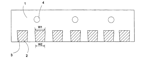
Figure 1 illustrates the cooling element according to the invention, seen in
cross-section.
The cooling element according to the invention comprises a housing part 1,
provided
with a channel system 4 for the cooling water circulation, and a lining formed
of
ceramic elements 2 applied to at least part of the surface of the housing
part.
The elements 2 of the ceramic lining are attached to the housing part 1 by
means
of a soldering/brazing agent in a way that results in a good thermal contact
between
the ceramic part and the housing part. The housing part 1 of the cooling
element
is typically made of copper, for example. Advantageously the housing part 1 of
the cooling element is made for instance by casting, such as by draw casting.
Typically
the channel system 4 is made by working, for instance by drilling, or in
connection
with the casting. At least one of the surfaces of the housing part 1 is
provided with
grooves 3, where there are arranged elements 2 of the ceramic lining,
typically fireproof


CA 02403844 2002-09-20
WO 01/71267 PCT/FI01/00280
3
bricks. In between the housing part 1 of the cooling element and the ceramic
elements 2, there is made a joint enabling a good thermal contact by means of
a soldering/brazing agent. The ceramic elements 2 are arranged to be held in
the grooves in a shape-locking fashion, when the element is in a position
where
the groove opens downwardly. The grooves 3 can be for instance narrowing at
the groove bottom towards the element surface, in which case the groove width
W, at the groove bottom is larger than the groove width W2 on the surface
level.
In a typical embodiment, the groove width W2 on the housing part surface level
is 2 - 10 mm narrower than the groove width W, at the groove bottom. The
dimensional tolerance between the grooves 3 and the ceramic lining elements 2
is arranged to be such that the ceramic elements 2 can be inserted in the
grooves 3 at the ends thereof, from the side of the element housing part. In
between the ceramic elements 2 and the housing part 1, at least at the
junction
surfaces, there is applied an intermediate layer of the soldering/brazing
agent,
with a melting temperature that is lower than the melting temperature of the
pieces to be joined. The soldering/brazing agent can be brought in the joint
for
instance in the form of foil or powder. The soldering/brazing agent can also
be
readily included in at least one of the parts to be joined. For instance, the
elements of a ceramic lining can include a layer of soldering/brazing agent on
the junction surface, in which case said elements are immersed in the molten
soldering/brazing agent prior to installing them in the grooves of the housing
part. In that case a soldering/brazing agent layer is absorbed in the surface
of
the ceramic lining element. The soldering/brazing agent can be for example a
copper-based alloy with a melting temperature within the range of 400 - 700
C.
When the ceramic lining elements 2, for instance fireproof bricks, and the
soldering/brazing agent are arranged in the groove, the junction area of at
least
the pieces to be joined together is heated up to a temperature where the
soldering/brazing agent melts and makes a good thermal contact between the
bricks and the housing part. It is also possible to bring more
soldering/brazing
agent to the junction area during the heating process. The heating can be
carried out in the same step where a possible blocking joint of the cooling


CA 02403844 2002-09-20
WO 01/71267 PCT/FI01/00280
4
channel is made.

The cooling elements according to the invention can be used in several
different
applications. A typical target for the use of the cooling element according to
the
invention is for instance the ceiling of the lower furnace in a flash smelting
furnace. There the shape of the grooves made in the cooling element prevents
the ceramic lining elements from falling off the grooves, although the element
is
installed so that the lining side is directed downwards. The grooves do not
have
to be narrowed very much, because the temperature of the elements on the
furnace side is higher than the temperature on the side that is directed away
from the furnace, in which case thermal expansion causes pressure tension on
the surface that is located on the furnace side. Typical measures for a
cooling
element according to the invention are: width: 0.25 - 1 m, length 1 - 2 m, and
thickness of the housing part 100 - 200 mm, of which the thickness of the
grooved part constitutes roughly a half.

Representative Drawing
A single figure which represents the drawing illustrating the invention.
Administrative Status

For a clearer understanding of the status of the application/patent presented on this page, the site Disclaimer , as well as the definitions for Patent , Administrative Status , Maintenance Fee  and Payment History  should be consulted.

Administrative Status

Title Date
Forecasted Issue Date 2010-06-01
(86) PCT Filing Date 2001-03-21
(87) PCT Publication Date 2001-09-27
(85) National Entry 2002-09-20
Examination Requested 2006-02-28
(45) Issued 2010-06-01
Deemed Expired 2012-03-21

Abandonment History

There is no abandonment history.

Payment History

Fee Type Anniversary Year Due Date Amount Paid Paid Date
Application Fee $300.00 2002-09-20
Maintenance Fee - Application - New Act 2 2003-03-21 $100.00 2002-09-20
Registration of a document - section 124 $100.00 2002-11-12
Maintenance Fee - Application - New Act 3 2004-03-22 $100.00 2004-02-10
Maintenance Fee - Application - New Act 4 2005-03-21 $100.00 2005-02-17
Maintenance Fee - Application - New Act 5 2006-03-21 $200.00 2006-02-21
Request for Examination $800.00 2006-02-28
Maintenance Fee - Application - New Act 6 2007-03-21 $200.00 2007-02-16
Maintenance Fee - Application - New Act 7 2008-03-21 $200.00 2008-02-28
Maintenance Fee - Application - New Act 8 2009-03-23 $200.00 2009-03-13
Maintenance Fee - Application - New Act 9 2010-03-22 $200.00 2010-02-23
Registration of a document - section 124 $100.00 2010-03-04
Final Fee $300.00 2010-03-05
Owners on Record

Note: Records showing the ownership history in alphabetical order.

Current Owners on Record
OUTOTEC OYJ
Past Owners on Record
LEPPANEN, YRJO
OUTOKUMPU OYJ
SAARINEN, RISTO
Past Owners that do not appear in the "Owners on Record" listing will appear in other documentation within the application.
Documents

To view selected files, please enter reCAPTCHA code :


To view images, click a link in the Document Description column. To download the documents, select one or more checkboxes in the first column and then click the "Download Selected in PDF format (Zip Archive)" or the "Download Selected as Single PDF" button.

List of published and non-published patent-specific documents on the CPD .

If you have any difficulty accessing content, you can call the Client Service Centre at 1-866-997-1936 or send them an e-mail at CIPO Client Service Centre.


Document
Description 
Date
(yyyy-mm-dd) 
Number of pages   Size of Image (KB) 
Description 2002-09-20 4 175
Representative Drawing 2003-01-17 1 6
Cover Page 2003-01-17 1 37
Drawings 2002-09-20 1 10
Claims 2002-09-20 2 74
Abstract 2002-09-20 1 66
Description 2009-04-09 5 204
Claims 2009-04-09 2 61
Cover Page 2010-05-05 1 39
PCT 2002-09-20 11 448
Assignment 2002-09-20 3 123
Assignment 2002-11-12 3 73
Prosecution-Amendment 2006-02-28 1 36
Prosecution-Amendment 2006-02-28 1 38
Assignment 2010-03-04 2 146
Correspondence 2010-03-05 2 72
Prosecution-Amendment 2008-10-17 2 60
Prosecution-Amendment 2009-04-09 7 261