Note: Descriptions are shown in the official language in which they were submitted.
CA 02403931 2002-09-18
WATER JET PROPULSION APPARATUS
FIELD OF THE INVENTION
The present invention relates to a water jet propulsion apparatus for use
in a boat.
BACKGROUND OF THE INVENTION
A known conventional water jet propulsion apparatus is as shown in FIG.
6 (Japanese Utility Model Registration No. 2,548,210).
The water jet propulsion apparatus is attached to the rear part of a boat and
has a stator (duct) 1 forming a channel, an impeller 2 rotatably disposed in
the stator 1, an impeller shaft 3 rotatably supported by a bearing 1a in the
stator 1 and coupled to the rear part of the impeller 2, a collar 4 provided
around the impeller shaft 3, and a waterproof seal 5 provided between the
collar 4 and the bearing 1a of the stator 1.
A drive shaft 6 is coupled to the front part of the impeller 2. When the
drive shaft 6 is driven by a not-illustrated engine, the impeller 2 is rotated
and a water stream is jetted rearward (to the right in the drawing), thereby
propelling the boat body.
In the above-described conventional eater jet propulsion apparatus, since
the front end 4a of the collar 4 is only in contact with the rear end 2a of
the
impeller 2, there is a problem such that water enters from a gap between
Jj-11740/cs
CA 02403931 2002-09-18
-2-
the front end 4a of the collar 4 and the rear end 2a of the impeller 2, comes
into contact with the surface of the impeller shaft 3, and corrodes the
surface of the impeller shaft 3.
This problem can be solved by making the impeller shaft 3 of a corrosion-
resistant material (for example, stainless steel). In this case, however,
another problem that the impeller shaft becomes expensive arises.
An object of the invention is to provide a water jet propulsion apparatus
which can solve the above problems and prevent water from coming into
contact with the impeller shaft.
SUMMARY OF THE INVENTION
To achieve the object, a water jet propulsion apparatus of the present
invention includes a stator forming a channel, an impeller rotatably
disposed in the stator, an impeller shaft rotatably supported in the stator
and coupled to the impeller, a collar provided around the impeller shaft,
and a waterproof seal provided between the collar and the stator, and is
characterized in that the collar is coupled to the impeller via the
waterproof seal.
In an aspect of the invention, the water jet propulsion apparatus is
characterized in that, in the water jet propulsion apparatus according to
the above, the impeller shaft is coupled to the rear part of the impeller by
screwing, a drive shaft is coupled to the front part of the impeller by
splining, a buffer for the rear end of the drive shaft is provided between
the front end of the impeller shaft in the impeller and the rear end of the
drive shaft, and the peripheral portion of the buffer is formed in a shape
such that air escapes from the impeller shaft side toward the drive shaft
side when the impeller shaft is screwed.
BRIEF DESCRIPTTON OF THE DRAWINGS
J1-11740/cs
CA 02403931 2002-09-18
-3-
Preferred embodiments of the invention are shown in the drawings,
wherein:
FIG. 1 is a partly-cutaway schematic side view showing an example of a
small planing boat using an embodiment of a water jet propulsion
apparatus according to the invention.
FIG. 2 is a schematic plan view of the small planing boat.
FIG. 3 is a cross section showing a jet pump 30.
FIGS. 4A and 4B are a view seen from the back of a boat body and a partly
cutaway side view, respectively, showing a buffer 50.
FIGS. 5A and 5B are a view seen from the back of the boat body and a side
view, respectively, showing a modification of the buffer.
FIG. 6 is a diagram for explaining a prior art.
DETAILED DESCRIPTION OF THE PREFERRED EMBODIMENTS
An embodiment of the invention will be described hereinbelow with
reference to the drawings.
FIGS. 1 and 2 are a partial cutaway schematic side view and a schematic
plan view each showing an example of a small planing boat using an
embodiment of the water jet propulsion apparatus according to the
invention.
As shown in the drawings (mainly FIG. 1), this small planing boat 10 is a
saddle-type small boat. An occupant sits on a seat 12 of a boat body 11, and
can drive the small planing boat 11 by gripping a steering handle 13 with a
throttle lever.
JJ-11740/cs
CA 02403931 2002-09-18
-4-
The boat body 11 has a floating body structure obtained by bonding a hull
14 and a deck 15 and forming a space 16 on the inside. In the space 16, an
engine 20 is mounted on the hull 14, and a water jet propulsion apparatus
(hereinbelow, also called a jet pump) 30 as propulsion means driven by
the engine 20 is provided in the rear part of the hull 14.
The jet pump 30 has an impeller 32 disposed in a channel 18 extending
from an intake 17 opened in the bottom of the boat to a jet port 31c2
opened in the rear end of the boat and a deflector 38. A shaft (drive shaft)
22 for driving the impeller 32 is coupled to an output shaft 21 of the
engine 20 via a coupler 23. Therefore, when the impeller 32 is rotated by
the engine 20 via the coupler 23 and shaft 22, water taken from intake 17 is
jetted from the jet port 31c2 to the outside via the deflector, thereby
propelling the boat body 21. The number of revolutions of the engine 20,
that is, the propulsion generated by the jet pump 30 is controlled by an
operation of turning a throttle lever 13a (refer to FIG. 2) of the steering
handle 13. The deflector 38 is linked with the steering handle 13 via a not-
illustrated control wire and is turned by the operation of the handle 13,
thereby enabling the course of the boat body 11 to be changed.
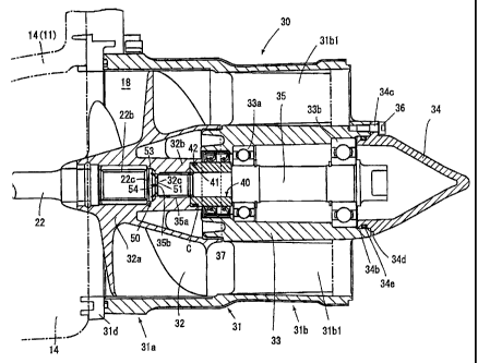
FIG. 3 is a cross section showing the jet pump 30.
As shown in the diagram, the jet pump 30 has a stator (duct) 31 forming
the channel 18 communicated with the intake 17 (refer to FIG. 1) provided
on the bottom of the boat body 11, the impeller 32 disposed in the stator 31,
a bearing 33 of the impeller provided in the stator 31, and a cap 34 for
closing the rear end of the bearing 33.
The jet pump 30 is detachably attached to the hull 14 by fixing a flange 31d
formed in the front portion of the stator 31 by a not-shown bolt.
J]-1174o/cs
CA 02403931 2002-09-18
-5-
The stator 31 has an impeller housing part 31a, a bearing housing part 31b,
and a nozzle part 31c (refer to FIG. 1). The impeller housing part 31a and
the bearing housing part 31b are formed integrally. The bearing 33 is
integrally formed in the bearing housing part 31b via a stationary blade
31b1.
The front part of a boss 32a of the impeller 32 is engaged with a spline 22b
formed in the rear end of the drive shaft 22, so that the impeller 32 rotates
with the drive shaft 22. The front end 22a of the drive shaft 22 is coupled
to the output shaft 21 of the engine '?0 mounted on the boat body 11 via
the coupler 23 (FIG. 1).
On the other hand, an impeller shaft 35 for supporting the rear part 32b of
the boss 32a of the impeller 32 is rotatably supported by the bearing 33 via
ball bearings 33a and 33b. A male screw 35a is formed at the tip of the
impeller shaft 35 and is screwed in a female screw formed in the boss rear
part 32b of the impeller 32, thereby coupling the impeller 32 and the
impeller shaft 35.
Therefore, the front part of the boss 32a of the impeller 32 is coupled to the
drive shaft 22, the rear part 32b of the boss is coupled to the impeller shaft
35, and the impeller 32 rotates with the drive shaft 22 and the impeller
shaft 35.
A collar 40 is attached to the periphery of the impeller shaft 35, and a
waterproof seal 37 is provided between the collar 40 and the bearing 33 of
the stator. Therefore, water does not enter the bearing 33 from the gap
between the bearing 33 and the collar 40.
The collar 40 is also coupled to the rear part 32b of the boss of the impeller
32 via a waterproof seal 42. Therefore, water does not enter from the gap C
between the collar 40 and the rear part 32b of the boss of the impeller 32
JJ-11740/cs
CA 02403931 2002-09-18
-6-
toward the peripheral face of the impeller shaft 35.
In the embodiment, the waterproof seal 42 takes the form of an O ring
attached to a ring-shaped groove 41 formed in the peripheral face of the
collar 40.
In the boss 32a of the impeller, a buffer 50 for the rear end 22c of the drive
shaft is provided between the front end 35b of the impeller shaft 35 and
the rear end 22c of the drive shaft 22. The peripheral portion of the buffer
50 is formed in a shape such that air escapes from the impeller shaft 35
side toward the drive shaft 22 side when said impeller shaft 35 is screwed
in the boss 32a of the impeller.
Concretely, the buffer 50 is made of rubber.
FIG. 4 is a diagram showing the buffer 50; FIG. 4A is a view seen from the
back of the ship body, and FIG. 4B is a partial cutaway side view of FIG. 4A.
As shown in FIGS. 3 and 4, the buffer 50 has an engagement part 51 with a
screw hole 32c in the boss 32a of the impeller and a large diameter part 53
closely attached to the internal face of the boss 32a of the impeller. An air
escape groove 54 extending from an external face 52 of the engagement
part 51 to some midpoint of the large diameter part 53 is formed.
When such an air escape groove 54 is formed, at the time of screwing the
impeller shaft 35 into the boss 32a of the impeller, air (or grease) existing
between the front end 35b of the impeller shaft and the buffer 50 is guided
to the air escape groove 54 in association with screwing of the impeller
shaft 35 and escapes from the front end portion 54a of the air escape
groove 54 toward the drive shaft 22 side while slightly deforming the large
diameter part 53. Since the drive shaft 22 and the impeller shaft 35 are
splined, the air (or grease) can escape along the spline.
J]-1174o/cs
CA 02403931 2002-09-18
After screwing the impeller shaft 35 into the boss 32a of the impeller, the
Large diameter part 53 of the buffer 50 is closely attached to the internal
face
of the boss 32a of the impeller. Consequently, the buffer 50 also plays the
role of interrupting water entering from the drive shaft 22 side to the
impeller shaft 35 side.
FIG. 5 is a diagram showing a modification of the buffer; FIG. 5A is a view
seen from the back of the boat body, and FIG. 5B is a side view.
A buffer 55 is constructed in such a manner that a large diameter part 56
which is closely attached to the inner face of the boss 32a is formed in a
ring-shaped thin seal lip to make air (or grease) easily escape toward the
drive shaft 22 side. Also by such a configuration, at the time of screwing
the impeller shaft 35 into the boss 32a of the impeller, air (or grease)
existing between the front end 35b of the impeller shaft and the buffer 50
slightly deforms the seal Lip 56 in association with the screwing of the
impeller shaft 35 and escapes towards the drive shaft 22 side. After the
impeller shaft 35 is screwed in the boss 32a of the impeller, the seal lip 53
is
closely attached to the internal face of the boss 32a of the impeller.
Consequently, the buffer 55 also plays the role of interrupting water
entering from the drive shaft 22 side to the impeller shaft 35 side.
As shown in FIG. 3, in the front part of the cap 34, an insertion part
(cylindrical part) 34b to the rear part of the bearing 33 is formed and three
insertion holes 34c (only one insertion hole is shown) of screws 36 are also
formed. In the cylindrical insertion part 34b, an attachment groove of an
O ring 34e is formed.
Therefore, the cap 34 is attached to the rear part of the bearing 33 by
attaching the O ring 34e to the insertion part 34b, inserting (force-fitting)
the insertion part 34b into the rear part of the bearing 33 as shown in FIG.
JJ-11740/cs
CA 02403931 2002-09-18
_ 8
3, and screwing the insertion part 34b with the screws 36.
In a state where the cap is attached, invasion of water to the bearing 33 is
interrupted by the O ring 34e.
A partial notch 34d is farmed in a contact face with the bearing 33 of the
cap 34. At the time of maintenance, the cap 34 can be easily detached by
unscrewing the screws 36 and inserting the tip of a tool (for example, a
driver) into the notch 34d.
The water jet propulsion apparatus as described above produces actions
and effects as follows.
(a) The water jet propulsion apparatus includes the stator 31 forming
the channel 18, the impeller 32 rotatably disposed in the stator 31, the
impeller shaft 35 rotatably supported in the stator 31 and coupled to the
impeller 32, the collar 40 provided around the impeller shaft 35, and a
waterproof seal 37 provided between the collar 40 and the stator 31, and
the collar 40 is coupled to the impeller 32 via the waterproof seal 42.
Consequently, water does not enter from the gap C between the collar 40
and the impeller 32 toward the impeller shaft 35.
Therefore, the surface of the impeller shaft 35 does not corrode (or at least
does not corrode conspicuously) and, as a result, it is not always necessary
to make the impeller shaft of a corrosion-resistant material (such as
stainless steel).
Since the impeller shaft 35 can be made of iron or the like, the price of the
impeller shaft 35 can be reduced.
Preferably, the collar 40 is made of a corrosion-resistant material (such as
stainless steel).
1J-11740/cs
CA 02403931 2002-09-18
-(~-
(b) The impeller shaft 35 is coupled to the rear part of the impeller 32 by
screwing, and a drive shaft 22 is coupled to the front part of the impeller 32
by splining, so that the impeller shaft 35 and the impeller 32 can be
detached in a coupled state from the drive shaft.
In the embodiment, by detaching the bolt fixing the jet pump 30 to the boat
body 11, the whole jet pump 30 can be taken out to the rear side.
Since the buffer 50 (or 55) for the rear end 22c of the drive shaft is
provided
between the front end 35b of the impeller shaft 35 in the impeller 32 and
the rear end 22c of the drive shaft 22, a shock at the time of attaching the
impeller 32 to the rear end 22c of the drive shaft is lessened.
In the case of such a configuration, if it is assumed that n o
countermeasure is taken, at the time of screwing the impeller shaft 35 to
the rear part of the impeller 32, air (or grease) existing between the
impeller shaft 35 and the buffer 50 (or 55) cannot escape, and a problem
such that the buffer 50 is excessively deformed occurs.
In contrast, in the water jet propulsion apparatus of the embodiment, the
peripheral portion of the buffer 50 (or 55) is formed in a shape such that air
escapes from the impeller shaft 35 side toward the drive shaft 22 side when
the impeller shaft is screwed. Thus, excessive deformation of the buffer 50
can be prevented.
The water jet propulsion apparatus of the present invention includes a
stator forming a channel, an impeller rotatably disposed in the stator, an
impeller shaft rotatably supported in the stator and coupled to the
impeller, a collar provided around the impeller shaft, and a waterproof
seal provided between the collar and the stator. In the water jet
propulsion apparatus, the collar is coupled to the impeller via the
JJ-11~~/cs
CA 02403931 2002-09-18
-10-
waterproof seal. Consequently, in the water jet propulsion apparatus,
water does not enter from the gap between the collar and the impeller
toward the impeller shaft.
Therefore, the surface of the impeller shaft does not corrode (or at least
does not corrode conspicuously) and, as a result, it is not always necessary
to make the impeller shaft of a corrosion-resistant material.
As for the water jet propulsion apparatus of an embodiment of the
invention, in the water jet propulsion apparatus according to the above,
the impeller shaft is coupled to the rear part of the impeller by screwing,
and a drive shaft is coupled to the front part of the impeller by splining, so
that the impeller shaft and the impeller can be detached in a coupled state
from the drive shaft.
Since a buffer for the rear end of the drive shaft is provided between the
front end of the impeller shaft in the impeller and the rear end of the
drive shaft, a shock at the time of attaching the impeller to the rear end of
the drive shaft is lessened.
In the case of such a configuration, if it is assumed that no
countermeasure is taken, at the time of screwing the impeller shaft to the
rear part of the impeller, air (or grease) existing between the impeller shaft
and the buffer cannot escape, and a problem such that the buffer is
excessively deformed occurs.
In contrast, in the water jet propulsion apparatus of the above
embodiment, the peripheral portion of the buffer is formed in a shape
such that air escapes from the impeller shaft side toward the drive shaft
side when the impeller shaft is screwed. Thus, excessive deformation of
the buffer can be prevented.
JJ-1174o/cs
CA 02403931 2002-09-18
-11-
Although various preferred embodiments of the present invention have
been described herein in detail, it will be appreciated by those skilled in
the
art, that variations may be made thereto without departing from the spirit
of the invention or the scope of the appended claims.
JJ-11740/ cs