Language selection

Search

Patent 2404072 Summary

Third-party information liability

Some of the information on this Web page has been provided by external sources. The Government of Canada is not responsible for the accuracy, reliability or currency of the information supplied by external sources. Users wishing to rely upon this information should consult directly with the source of the information. Content provided by external sources is not subject to official languages, privacy and accessibility requirements.

Claims and Abstract availability

Any discrepancies in the text and image of the Claims and Abstract are due to differing posting times. Text of the Claims and Abstract are posted:

  • At the time the application is open to public inspection;
  • At the time of issue of the patent (grant).
(12) Patent: (11) CA 2404072
(54) English Title: SWITCHING ELEMENT FOR A VALVE TRAIN OF AN INTERNAL COMBUSTION ENGINE
(54) French Title: COMMUTATEUR DE COMMANDE DES CULBUTEURS ET POUSSOIRS DE SOUPAPES DE MOTEUR A COMBUSTION INTERNE
Status: Deemed expired
Bibliographic Data
(51) International Patent Classification (IPC):
  • F01L 1/12 (2006.01)
  • F01L 1/14 (2006.01)
  • F01L 1/245 (2006.01)
  • F01L 13/00 (2006.01)
(72) Inventors :
  • SCHNELL, OLIVER (Germany)
(73) Owners :
  • SCHAEFFLER TECHNOLOGIES AG & CO. KG (Germany)
(71) Applicants :
  • INA-SCHAEFFLER KG (Germany)
(74) Agent: MACRAE & CO.
(74) Associate agent:
(45) Issued: 2009-12-29
(22) Filed Date: 2002-09-18
(41) Open to Public Inspection: 2003-03-19
Examination requested: 2007-08-15
Availability of licence: N/A
(25) Language of filing: English

Patent Cooperation Treaty (PCT): No

(30) Application Priority Data:
Application No. Country/Territory Date
101 46 131.3 Germany 2001-09-19

Abstracts

English Abstract

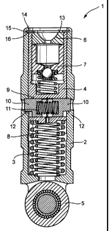
The invention proposes a switching element (1) for a valve train of an internal combustion engine, said switching element comprising an outer element (2) and an inner element (4) that is arranged for axial displacement in a bore (3) of the outer element (2), each of the outer element (2) and the inner element (4) comprising at least one reception (12, 9) aligned to each other in an axially distant relative position which is achieved through a lost motion spring (8), at least one piston (10) being arranged in at least one of the receptions (12, 9) for sliding toward the other of the receptions (12, 9) to couple the inner element (4) to the outer element (2) in said relative position, and a high-position stop for defining said relative position being arranged between the inner element (4) and the outer element (2). The inventive high-position stop is made as a separate element (16) such as a disk or a circlip with a variable thickness that is fixed on one of the outer element (2) and the inner element (4) and cooperates with a stop surface of the other of the outer element (2) and the inner element (4). These extremely simple fabrication measures enable an alignment of the receptions (9, 12) for achieving coupling.


French Abstract

L'invention propose un commutateur (1) de commande des culbuteurs et poussoirs de soupapes de moteur à combustion interne, ledit commutateur comprenant un élément externe (2) et un élément interne (4) qui est conçu pour un déplacement axial dans un alésage (3) de l'élément externe (2), chacun de l'élément externe (2) et de l'élément interne (4) comprenant au moins une réception (12, 9) alignée l'une par rapport à l'autre dans une position relative axialement éloignée qui est obtenue par un ressort à perte de mouvement (8), au moins un piston (10) étant disposé dans au moins une des réceptions (12, 9) pour glisser vers l'autre réception (12, 9) afin de coupler l'élément interne (4) à l'élément externe (2) dans cette position relative, et une butée en position élevée pour définir ladite position relative étant disposée entre l'élément interne (4) et l'élément externe (2). La butée en posiiton élevée de l'invention est constituée comme un élément séparé (16) tel qu'un disque ou un circlipcirclip ayant une épaisseur variable qui est fixe sur l'un ou l'autre de l'élément externe (2) et de l'élément interne (4) et coopère avec une surface de butée de l'autre élément parmi l'élément externe (2) et l'élément interne (4). Ces mesures de fabrication extrêmement simples permettent un alignement des réceptions (9, 12) pour obtenir un couplage.

Claims

Note: Claims are shown in the official language in which they were submitted.


6

What is claimed is:

1. A switching element for valve deactivation in a valve train of an internal
combustion engine, said switching element comprising an outer element
and an inner element that is arranged for axial displacement in a bore of the
outer element, each of the outer element and the inner element comprising
at least one reception aligned to each other in an axially distant relative
position which is achieved through a lost motion spring, at least one piston
being arranged in at least one of the receptions for sliding toward the other
of the receptions to couple the inner element to the outer element in said
relative position, and a high-position stop for defining said relative
position
being arranged between the inner and the outer element, wherein the high-
position stop is made as a separate element of variable thickness that is
fixed on one of the outer element and the inner element and cooperates
with a stop surface of the other of the outer element and the inner element.

2. The switching element of Claim 1, wherein the switching element is made
as a cam follower in a tappet push rod drive, an end face of the inner
element does not project beyond an end face of the outer element that is
directed toward the tappet push rod, the bore of the outer element
comprises an annular groove in which the separate element is fixed, and
the separate element projects into the bore of the outer element so that, in
the relative position, the end face of the inner element bears as a stop
surface against the separate element.

3. The switching element of Claim 1, wherein coupling is achieved by two
pistons that extend diametrically opposite each other in the reception of the
inner element, which reception is made as a radial bore, said pistons being
aligned to the receptions of the outer element in the relative position.


7

4. The switching element of Claim 2, wherein coupling is achieved by two
pistons that extend diametrically opposite each other in the reception of the
inner element, which reception is made as a radial bore, said pistons being
aligned to the receptions of the outer element in the relative position.

5. The switching element of Claim 1, wherein the separate element also
serves as a safety device for the inner element relative to the outer element.

6. The switching element of Claim 1, wherein the separate element of variable
thickness is a disk.

7. The switching element of Claim 1, wherein the separate element of variable
thickness is a circlip.

Description

Note: Descriptions are shown in the official language in which they were submitted.


CA 02404072 2002-09-18
3893-18-CA

Switching element for a valve train of an internal combustion engine
Field of the invention

The invention concerns a switching element for a valve train of an internal
combustion engine, preferably for valve deactivation, said switching element
comprising an outer element and an inner element that is arranged for axial
displacement in a bore of the outer element, each of the outer element and the
inner element comprising at least one reception aligned to each other in an
axially
distant relative position which is achieved through a lost motion spring, at
least
one piston being arranged in at least one of the receptions for sliding toward
the
other of the receptions to coupie the inner element to the outer element in
said
relative position, and a high-position stop for defining said relative
position being
arranged between the inner and the outer element.

Background of the invention

A switching element of the pre-cited type is disclosed in the generic prior
art
document DE 199 15 531 which shows a switchable cam follower for a tappet
push rod drive_ The high-position stop for defining the relative position is
formed by
a piston-like element arranged in the inner element. This piston-like element
projects radially outward into a longitudinal groove of the outer element. In
the
axially extracted state of the inner element from the outer element, the
piston-like
element abuts against one end of the longitudinal groove. The purpose of this
is to
create an aligned arrangement of a coupling bore made in the outer element for
a
piston arranged in the inner element for achieving coupling.

A drawback of this prior art is that an adjustment of lash in the coupling is
relatively
complicated and cost-intensive. It is clear that the reception (coupling bore)
in the


CA 02404072 2002-09-18

3893-18-CA 2

outer element for receiving the piston must be configured with a slight lash
relative
to the outer peripheral surface of the piston. This lash and the high position
differ
from switching element to switching element due to fabrication conditions. The
relatively wide range of variance of this mechanical idle travel in switching
elements is, however, undesirable.

Therefore, to keep the coupling lash or its variance within acceptable limits,
pistons to be used for coupling are sorted into groups. This procedure is
extremely
expensive from the point of view of fabrication and measuring techniques. For
example, the switching elements are first completely mounted, the lash is then
measured following which, the switching elements are dismounted again and an
appropriate piston is then chosen for coupling. It is equally conceivable to
group
the high-position stops provided on the longitudinal grooves of the outer
elements.
If, as disclosed in DE 42 06 166, two pistons are used for coupling, the stop
measures described above prove to be quasi impossible. The aligned position of
the coupling bores that are situated diametrically opposite each other in the
inner
element is realized by the contact of the two axially displaceable parts of
the
switching element on the base circle of the cam. From the point of view of
fabrication and measuring techniques, the adjustment of the lash of the
coupling is
implemented in an extremely complicated and expensive manner by a pairing of
corresponding switching elements (in this case, cup tappets to cam pairs or
cam
shafts. Under certain circumstances, a too large variation of lash will have
to be
allowed.

Objects of the invention

It is an object of the invention to provide an improved switching element of
the pre-
cited type in which the aforesaid drawbacks are eliminated by simple measures.
This and other objects and advantages of the invention will become obvious
from
the following detailed description.


CA 02404072 2002-09-18

3893-18-CA 3
Summary of the invention

The invention achieves the above objects by the fact that the high-position
stop is
made as a separate element of variable thickness such as a disk or a circlip
that is
fixed on one of the outer element and the inner element and cooperates with a
stop surface of one of the inner element and the outer element. In a
particularly
advantageous embodiment of the invention, coupling is achieved by two pistons
that extend diametrically opposite each other in the reception of the inner
element,
which reception is made as a radial bore, said pistons being aligned to the
receptions of the outer element in the relative position.

The separate element of the invention disposed, for example, in the bore of
the
outer eiement, forms a simple, tilt-free and adjustable high-position stop.
The
initially described drawbacks are thus eliminated by simple measures. During a
mounting of the switching element (disk, circlip or the like), different
thicknesses of
the separate element can be chosen to adjust the mechanical idle travel of the
at
least one coupling element (preferably two) relative to the reception in which
it is
arranged. This means in other words, that in the axially extracted state of
the inner
element from the outer element, the annular high-position stop enables the
axes of
the receptions and the axes of the pistons to be aligned or adjusted to one
another
for achieving coupling. In place of a variation of the thickness of the
separate
element, the height of the inner element with its end face may also be varied.

The scope of protection of the invention extends explicitly to all types of
switching
elements in valve trains such as cam followers in tappet push rod drives, cup
tappets and support elements for finger levers. The invention extends likewise
to
switching elements that are installed directly in lever-type cam followers.
The
switching elements may be designed for complete de-actuation or for switching
to
different cam lifts_

According to a further feature of the invention, the separate element serves
at the
same time as a safety device against loss and for transportation. In this way,


CA 02404072 2002-09-18

3893-18-CA 4
additional securing measures that may possibly have to be removed prior to
mounting the switching element in the intemal combustion engine can be
dispensed with.

The invention will now be described more closely with reference to the
appended
drawing.

Brief description of the drawing

The sole figure shows, in a longitudinal section, a switching element of the
invention made in the present case as a roller tappet for a tappet push rod
drive.
Detailed description of the drawing

The figure discloses a switching element 1 that is configured as a roller
tappet.
The switching element is designed for switching to different valve lifts, in
the
present case, for switching between a zero lift and a full lift. The switching
element
1 comprises an outer element 2 in whose recess 3 an inner element 4 is
received
for axial displacement.

On one end, the switching element 1 comprises a roller 5 for contacting a cam
and
acts at the opposite end through a support 6 on a tappet push rod in lifting
direction. In the present example, the support 6 is a part of a hydraulic lash
adjuster 7.

A lost motion spring 8 that does not need to be described here, acts axially
between the inner element 4 and the outer element 2. The inner element 4
comprises a radially extending cylindrical reception 9 in which two pistons 10
situated diametrically opposite each other are received for coupling the inner
element 4 to the outer element 2. The pistons 10 are biased radially outward
by
the force of a compression spring 11. In the relative position of the inner
element 4
to the outer element 2 shown in the figure, receptions 12 in the outer element
2


CA 02404072 2002-09-18

3893-18-CA 5

are situated opposite the pistons 10. For coupling, the pistons 10 can be
displaced
partially into the receptions 12 by the force of the compression spring 11.

In the maximum relative position of the inner element 4 to the outer element 2
shown in the figure, the end face 13 of the inner element 4 does not project
beyond the end face 14 of the outer element 2 that is directed toward the
tappet
push rod. In the vicinity of the end face 14, the bore 3 of the outer element
2
comprises an annular groove 15. An element 16 that defines a high-position
stop
for the inner element 4 in the uncoupled state is arranged in this annular
groove
15. In the present embodiment, the element 16 is configured as a disk. Thus,
the
end face 13 of the inner element 4 serves as a stop surface on the element 16.

As described in detail above, it is possible with the element 16 of variable
thickness, to realize in a very simple manner from the fabrication point of
view, an
alignment of the pistons 10 to the receptions 12 in the outer element 2. For
achieving this, during the mounting of the element 16, after this has been
previously measured, its thickness is chosen so that the pistons 10, of course
in
the unloaded state of the switching element, are surrounded by the receptions
12
uniformly and with slight lash upon coupling. The axes of the pistons 10 are
aligned to the axes of the receptions 12. In this way, an idle travel that the
inner
element 4 undergoes with the pistons 10 in the receptions 12 relative to the
outer
element 2 upon coupling to the outer element 2 and at the onset of loading by
the
cam is uniformly small throughout a series of switching elements 1 in internal
combustion engines of the same time. An excessive and undesired variance of
the
valve timing is excluded.

Representative Drawing
A single figure which represents the drawing illustrating the invention.
Administrative Status

For a clearer understanding of the status of the application/patent presented on this page, the site Disclaimer , as well as the definitions for Patent , Administrative Status , Maintenance Fee  and Payment History  should be consulted.

Administrative Status

Title Date
Forecasted Issue Date 2009-12-29
(22) Filed 2002-09-18
(41) Open to Public Inspection 2003-03-19
Examination Requested 2007-08-15
(45) Issued 2009-12-29
Deemed Expired 2014-09-18

Abandonment History

There is no abandonment history.

Payment History

Fee Type Anniversary Year Due Date Amount Paid Paid Date
Application Fee $300.00 2002-09-18
Registration of a document - section 124 $100.00 2003-01-29
Maintenance Fee - Application - New Act 2 2004-09-20 $100.00 2004-08-20
Maintenance Fee - Application - New Act 3 2005-09-19 $100.00 2005-08-17
Maintenance Fee - Application - New Act 4 2006-09-18 $100.00 2006-08-15
Request for Examination $800.00 2007-08-15
Maintenance Fee - Application - New Act 5 2007-09-18 $200.00 2007-08-23
Maintenance Fee - Application - New Act 6 2008-09-18 $200.00 2008-08-13
Maintenance Fee - Application - New Act 7 2009-09-18 $200.00 2009-08-28
Final Fee $300.00 2009-10-13
Maintenance Fee - Patent - New Act 8 2010-09-20 $200.00 2010-09-01
Maintenance Fee - Patent - New Act 9 2011-09-19 $400.00 2011-09-20
Registration of a document - section 124 $100.00 2012-06-22
Maintenance Fee - Patent - New Act 10 2012-09-18 $250.00 2012-09-05
Owners on Record

Note: Records showing the ownership history in alphabetical order.

Current Owners on Record
SCHAEFFLER TECHNOLOGIES AG & CO. KG
Past Owners on Record
INA-SCHAEFFLER KG
SCHAEFFLER KG
SCHAEFFLER TECHNOLOGIES GMBH & CO. KG
SCHNELL, OLIVER
Past Owners that do not appear in the "Owners on Record" listing will appear in other documentation within the application.
Documents

To view selected files, please enter reCAPTCHA code :


To view images, click a link in the Document Description column. To download the documents, select one or more checkboxes in the first column and then click the "Download Selected in PDF format (Zip Archive)" or the "Download Selected as Single PDF" button.

List of published and non-published patent-specific documents on the CPD .

If you have any difficulty accessing content, you can call the Client Service Centre at 1-866-997-1936 or send them an e-mail at CIPO Client Service Centre.


Document
Description 
Date
(yyyy-mm-dd) 
Number of pages   Size of Image (KB) 
Drawings 2009-04-30 1 31
Claims 2009-04-30 2 61
Representative Drawing 2002-11-22 1 15
Cover Page 2003-02-21 2 57
Abstract 2002-09-18 1 31
Description 2002-09-18 5 230
Claims 2002-09-18 2 63
Drawings 2002-09-18 1 34
Drawings 2007-08-15 1 33
Representative Drawing 2009-12-03 1 17
Cover Page 2009-12-03 2 58
Correspondence 2002-10-31 1 24
Assignment 2002-09-18 2 73
Assignment 2003-01-29 2 81
Prosecution-Amendment 2007-08-15 1 29
Prosecution-Amendment 2007-08-15 3 81
Prosecution-Amendment 2009-03-30 2 49
Prosecution-Amendment 2009-04-30 6 192
Correspondence 2009-10-13 1 30
Assignment 2012-06-22 36 1,477