Language selection

Search

Patent 2404171 Summary

Third-party information liability

Some of the information on this Web page has been provided by external sources. The Government of Canada is not responsible for the accuracy, reliability or currency of the information supplied by external sources. Users wishing to rely upon this information should consult directly with the source of the information. Content provided by external sources is not subject to official languages, privacy and accessibility requirements.

Claims and Abstract availability

Any discrepancies in the text and image of the Claims and Abstract are due to differing posting times. Text of the Claims and Abstract are posted:

  • At the time the application is open to public inspection;
  • At the time of issue of the patent (grant).
(12) Patent: (11) CA 2404171
(54) English Title: CONVEYOR SYSTEM
(54) French Title: CONVOYEUR
Status: Expired
Bibliographic Data
(51) International Patent Classification (IPC):
  • B65G 21/20 (2006.01)
  • B65G 21/04 (2006.01)
  • B65G 21/22 (2006.01)
  • B65G 39/20 (2006.01)
(72) Inventors :
  • TRIEB, HERBERT (Austria)
(73) Owners :
  • INNOVA PATENT GMBH (Austria)
(71) Applicants :
  • INNOVA PATENT GMBH (Austria)
(74) Agent: RIDOUT & MAYBEE LLP
(74) Associate agent:
(45) Issued: 2008-07-22
(22) Filed Date: 2002-09-18
(41) Open to Public Inspection: 2003-03-20
Examination requested: 2004-09-24
Availability of licence: N/A
(25) Language of filing: English

Patent Cooperation Treaty (PCT): No

(30) Application Priority Data:
Application No. Country/Territory Date
A 1501/2001 Austria 2001-09-20

Abstracts

English Abstract

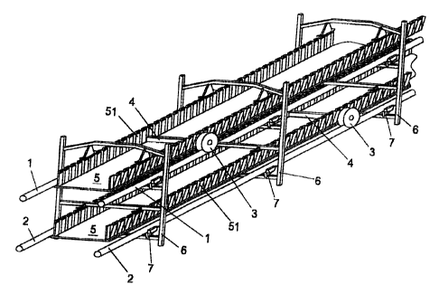
Conveyor system for transporting goods, having a conveyor belt (5) to which supporting beams (4) which are orientated transversely with respect to its direction of movement are attached, and also having two supporting webs which are arranged at a vertical distance from one another, are each formed by two supporting cables (1, 2) and along which rollers (3) which are arranged at the lateral ends of the supporting beams (4) can be moved. The supporting cables (1, 2) are connected to one another here by a multiplicity of retaining frames (6), (Fig. 1) .


French Abstract

Il s'agit d'un convoyeur destiné au transport de marchandise pourvu d'une courroie (5) à laquelle des poutres d'appui (4) transversales par rapport à la direction du mouvement de la courroie sont fixées. Le convoyeur possède aussi deux éléments d'appui qu'une distance verticale sépare l'un de l'autre et formés par deux câbles de soutien (1, 2) et le long desquels des galets (3) installés sur les extrémités latérales des poutres d'appui (4) peuvent bouger. Les câbles de soutien (1, 2) sont reliés l'un à l'autre par une multitude de cadres de retenue (6) (Fig. 1).

Claims

Note: Claims are shown in the official language in which they were submitted.


CLAIMS:

1. A conveyor system for transporting goods, having a
conveyor belt, to which supporting beams which are oriented
transversely with respect to its direction of movement are
attached, and having two supporting tracks arranged at a
vertical distance from one another and each formed by two
carrying cables, along which tracks rollers which are arranged
at the lateral ends of the supporting beams may be moved, the
carrying cables being connected together by a plurality of
holding frames, which comprise two at least approximately
vertically oriented beams and at least two at least
approximately horizontally oriented struts connecting these
together, and wherein guide means for the conveyor belt are
arranged on further at lest approximately horizontal struts,
which guide means bear from above on the conveyor belt, wherein
they bear in particular on the free upper ends of corrugated
sidewalls, which are constructed along the side edges of the
conveyor belt, to prevent the rollers from derailing.


2. A conveyor system according to claim 1, wherein a cover is
attached to the holding frames.


3. A conveyor system according to claim 1 or 2, wherein a
housing enclosing the conveyor belt at least on a plurality of
sides is attached to the holding frames.


4. A conveyor system according to any one of claims 1 to 3,
wherein the holding frames are attached to the carrying cables
by means of clamps, wherein the clamps are provided with a
means for increasing clamping force.


5. A conveyor system according to claim 4, wherein the clamps
are provided with two clamping jaws pivotable towards one
another, which each comprise a conical, curved or bevelled
surface and with which carrying brackets are associated, which


-6-


are provided with curved surfaces, whereby the contact pressure
of the clamping jaws against the carrying cables is increased
upon loading of the carrying brackets.


6. A conveyor system according to any one of claims 1 to 5,
wherein at least one further cable is provided above the upper
pair of carrying cables, which cable is likewise connected with
the holding frames.


-7-

Description

Note: Descriptions are shown in the official language in which they were submitted.


CA 02404171 2002-09-18

CQNVE.YQR SY5TE.M

The invention which comprises the subject matter relates to a
conveyor system for transporting goods, having a conveyor belt
or the like to which supporting beams which are orientated
transversely with respect to its direction of movexnent are
attached, and also having two supporting webs which are
arranged at a vertical distance from one another, are each
formed by two supporting cables and along which rollers which
are arranged at the lateral ends of the supporting beams can
be moved.

Iri such a conveyor system which is known from EU 745 545, it
is possible, when there are large bearing distances of the
supporting cables and when strong wind forces are acting, for
the supporting cables not to have the necessary positional
stability with respect to one another but instead change in
their position with respect to one another to such a degree
that the supporting rollers derail from the supporting cables,
as a result of which the system is no longer operative.

The invention wlxich comprises the subject matter is thus based
on the object of improving such a conveyor system to the
extent that satisfactory operation is ensured even under
unfavorable wind conditions. This is achie-ved according to the
invention in that the supporting cables are rigidly connected
to one another by a multiplicity of retaining frames-

The retaining frames are preferably embodied with two at least
approximately vertically orientated beams and with at least
two struts which connect the latte.r to one another and are at
least approximately horizontally orientated, the struts being
attached to the supporting cables by means of clamps. Here,
the at least approximately vertical beams can be connected by

-1-


CA 02404171 2002-09-18

further, at least approximately horizontal struts on which
guide devices for the conveyor belt are arranged.
According to one preferred embodiment, a cover is attached to
the retaining frames, or a housing which encloses the conveyor
belt on at least a plurality of sides is attached to the
retaining frame.

In addition, the clamps are preferably embodied with a device
for boosting the clamp3ng force, Here, the claraps can be
embodied with two clamping jaws which can pivot with respect
to one another and which are each embodied with a conical,
arched or beveled face and to which supporting clips which are
__sbodied wit:n conical faces are assignPd, as a re5ult of which
the pressing of the c.Larnpir,.g jaws against the supporting
cables is bocszed when the guppaxtin.g clips are los.ded.

Tn addition, further cables which are also connected to the
retaining frames can be provided above the upper pair of
supporting cables.

The subject matter of the invention is explained in more
detail below with reference to an exemplary embodiment which
is illustrated in the drawing, in which:

fig. 1. shows part of the system according to the invention in
an axonometric representation;

fig. 2 shows the system according to fig. 1 in a front view;
fig. 3 shows the system according to fig. 1 in a side view.
fig. 4 shows an attachment clamp in a side view; and

-2-


CA 02404171 2002-09-18

fig. 4a shows the attachment clamp according to fig_ 4 in
section along the line IV-IV.

A system according to the invention has two pairs of
supporting cables 1 and 2 which are guided and anchored at a
vertical distance from one another to the ends of the system
by means of supporting frames, and along which an enclosed
conJeyor belt 5 can be moved by means of supporting rollers 3
which are mounted at the ].ateral ends of supporting beams 4,
The conveyor belt 5 is attached to the undersides of the
supporting bea;ns 4. The conveyor belt 5 is embodied along its
side edges with corrugated eciges 51 which are necessary to be
able to guide it by means Qf deflection drums at the two end
stations of the system. Such a system is known from "the prior
art.

In order to be able to ensure the positional stability of the
supporting cables 1 and 2 with respect to one another, which
positional stability is necessary for disruption-free
operation of such a system, retaining frames 6 which are
arranged at intervals from one another are attached to the
supporting cables 1 and 2 by means of clamps 7 which hold the
supporting cables 1 and 2 at fixed distances from one another.
As the conveyor belt 5 is turned through 180l by means of a
turning device in the end regions in which it is deflected,
both strands thereof are directed upward.

As this is clear and in particular from fig. 2, the retaining
frames 6 are composed of vertical beams 61 and 62 which are
connected to one another by means of approximately horizontal
struts 63, 64, 65 and 66. The retaining frames 6 are attached
to the supporting cables 1 and 2 by means of clamps 7 to which
the struts 64 and 66 are attached. Carriers 8 for guide faces
81 which serve to hold the corrugated edges 51 in positio.n and

-3-


CA 02404171 2002-09-18

at the same time to prevent the derailing of the supporting
rollers 3 project downward from the struts 63 and 65.

The supporting cables 1 and 2 are held at the given vertical
and horizontal distance$ from one another by means of the
retaining frames 6, as a result of which disruption-free
movement of the conveyor belt 5 is ensured under any operating
Cta.nditions. In addition, a cover or a housing for the system
can be arranged on the retaining frames 6. In addition, the
retai.ning frames 6 can also serve as carriers for lines 9 or
the l:~ke,

The construction and function of the clamps 7 will now be
explained with reference to figs 4 and 4a. The clamps 7 are
composed of two clamping jaws 71 whose upper parts 71a bear
against the supporting cables 1, 2. However, as the rollers 3
run oii the supporting cables 1, 2, the clamping jaws 71 can
bear only against the side faces of the supporting cables 1,
2. Below the upper parts 71a of the clamping jaws 71, these
are connected to one another by means of two bolts 72 in such
a way that they can be pivoted slightly toward one another
about an axis running in the di-rection of the supporting cable
1, 2.

In the lower region 71b, cutouts 73 are provided in the
clamping jaws 71, which cutouts 73 are embodied on their
underside with conical, arched or oblique faces. In these
cutouts 73 there are supporting bodies 74 which are embodied
with conical faces and to which supporting clips 75 which are
connect.ed to the struts 64 and 66 are attached. In addition,
two groups of plate springs 76 by which the upper parts 71a of
the clamping jaws 71 are pressed against the supporting cables
1, 2 are arranged between the supporting clips 75 and the

-4-


CA 02404171 2002-09-18

clamping jaws 71. Ghanges in the diameter of the supporting
cables 1 and 2 are absorbed by these plate springs 76.

As soon as a tensile force is exerted on the supporting bodies
74 by the retaining frames 6 via the supporting clips 75, the
lower regions 71b of the clamping jaws 71 are spread even
further apart from one another, as a result of which the
clamping force exerted on the supporting cables 1, 2 by the
upper jaw parts 71a is increased. This ensures that the clamps
7 are prevented from coming away from the supporting cables 1,
2 when there i5 boosted loading of the clamps 7 by the
supporting franes 6.

The retaining frames 6 thus reliably prevent derailing of the
rollers 3. ir, addition, the retaining frames 6 can serve as
carriers for a cover or a housing as well as for cables, pipes
or the like. ?n order to increase the supporting force, at
least one further pair of cables may also be provided, said
pair of cables being located above the supporting cables 1 and
the suppoXting frames 6 being also attached to them..This
further pair of cables may absorb some of the loads. In
addition, this pair of cables brings about a further
positional stabilization of the supporting cables. Finally,
this further pair of cables can serve as a carrier for a cQver
or for a housing.

-5-

Representative Drawing
A single figure which represents the drawing illustrating the invention.
Administrative Status

For a clearer understanding of the status of the application/patent presented on this page, the site Disclaimer , as well as the definitions for Patent , Administrative Status , Maintenance Fee  and Payment History  should be consulted.

Administrative Status

Title Date
Forecasted Issue Date 2008-07-22
(22) Filed 2002-09-18
(41) Open to Public Inspection 2003-03-20
Examination Requested 2004-09-24
(45) Issued 2008-07-22
Expired 2022-09-20

Abandonment History

There is no abandonment history.

Payment History

Fee Type Anniversary Year Due Date Amount Paid Paid Date
Registration of a document - section 124 $100.00 2002-09-18
Application Fee $300.00 2002-09-18
Maintenance Fee - Application - New Act 2 2004-09-20 $100.00 2004-08-06
Request for Examination $800.00 2004-09-24
Maintenance Fee - Application - New Act 3 2005-09-19 $100.00 2005-07-06
Maintenance Fee - Application - New Act 4 2006-09-18 $100.00 2006-09-14
Maintenance Fee - Application - New Act 5 2007-09-18 $200.00 2007-07-17
Final Fee $300.00 2008-04-16
Maintenance Fee - Application - New Act 6 2008-09-18 $200.00 2008-07-10
Maintenance Fee - Patent - New Act 7 2009-09-18 $200.00 2009-09-04
Maintenance Fee - Patent - New Act 8 2010-09-20 $200.00 2010-09-02
Maintenance Fee - Patent - New Act 9 2011-09-19 $200.00 2011-09-02
Maintenance Fee - Patent - New Act 10 2012-09-18 $250.00 2012-09-07
Maintenance Fee - Patent - New Act 11 2013-09-18 $250.00 2013-09-09
Maintenance Fee - Patent - New Act 12 2014-09-18 $250.00 2014-09-05
Maintenance Fee - Patent - New Act 13 2015-09-18 $250.00 2015-09-04
Maintenance Fee - Patent - New Act 14 2016-09-19 $250.00 2016-08-25
Maintenance Fee - Patent - New Act 15 2017-09-18 $450.00 2017-09-11
Maintenance Fee - Patent - New Act 16 2018-09-18 $450.00 2018-09-10
Maintenance Fee - Patent - New Act 17 2019-09-18 $450.00 2019-09-06
Maintenance Fee - Patent - New Act 18 2020-09-18 $450.00 2020-09-04
Maintenance Fee - Patent - New Act 19 2021-09-20 $459.00 2021-09-06
Owners on Record

Note: Records showing the ownership history in alphabetical order.

Current Owners on Record
INNOVA PATENT GMBH
Past Owners on Record
TRIEB, HERBERT
Past Owners that do not appear in the "Owners on Record" listing will appear in other documentation within the application.
Documents

To view selected files, please enter reCAPTCHA code :


To view images, click a link in the Document Description column. To download the documents, select one or more checkboxes in the first column and then click the "Download Selected in PDF format (Zip Archive)" or the "Download Selected as Single PDF" button.

List of published and non-published patent-specific documents on the CPD .

If you have any difficulty accessing content, you can call the Client Service Centre at 1-866-997-1936 or send them an e-mail at CIPO Client Service Centre.


Document
Description 
Date
(yyyy-mm-dd) 
Number of pages   Size of Image (KB) 
Representative Drawing 2002-11-22 1 21
Cover Page 2003-02-24 1 46
Claims 2007-10-26 2 53
Abstract 2002-09-18 1 17
Description 2002-09-18 5 233
Claims 2002-09-18 2 75
Drawings 2002-09-18 5 113
Claims 2007-01-30 2 55
Abstract 2008-07-10 1 17
Representative Drawing 2008-07-14 1 30
Cover Page 2008-07-14 1 56
Assignment 2002-09-18 4 150
Fees 2007-07-17 1 29
Prosecution-Amendment 2004-09-24 1 27
Fees 2004-08-06 1 39
Fees 2005-07-06 1 26
Fees 2006-09-14 1 28
Prosecution-Amendment 2006-11-08 2 75
Prosecution-Amendment 2007-01-30 4 88
Prosecution-Amendment 2007-06-19 2 76
Prosecution-Amendment 2007-10-26 4 90
Correspondence 2008-04-16 1 33
Fees 2008-07-10 1 34