Note: Descriptions are shown in the official language in which they were submitted.
CA 02402542 2002-09-20
1
TITLE OF THE INVENTION:
Electric Power Bar
FIELD OF THE INVENTION
.': The present invention relates to an electric power bar
and, more particularly, an electric power bar intended for
use with a computer.
BACKGROUND OF THE INVENTION
to Electric power bars are commonly used with computers to
provide electric power to the computers and ancillary
equipment such as printers and scanners. Preferably the
electric power bar has some surge protection, to protect the
computer from damage as a result of power surges. Such
1.'~ electric power bars are not specific to computers, and are
also used for a variety of other applications having nothing
to do with computers.
SL11~1ARY OF THE INVENTION
2'7 What is required is an electric power bar which is
specifically adapted for use with computers and ancillary
equipment.
According to the present invention there is provided an
25 electric power bar which includes a body and an electrical
cord adapted to plug the body into an electrical outlet of a
building. The body has one or more female receptacles which
receive power via the electrical cord. The female
receptacles are adapted to receive a plug from a computer or
30 ancillary equipment whereby power is supplied to the computer
or the ancillary equipment. The body also has incorporated
within in it a communications module which serves as a
conduit for sending and receiving messages. The body has at
least one of an Ethernet receptacle, an universal serial bus
CA 02402542 2002-09-20
2
receptacle, or a telephone jack receptacle in communication
with the communications module, so as to enable a computer to
be connected to the communications module.
In order to connect a computer at the present time a
number of adaptors are required. The electric power bar, as
described above, replaces these with a single body. It is
envisaged that communications module for the electric power
bar, described above, will include a phone line in receptacle
and a phone line out receptacle. It will be appreciated,
however, that as wireless networks become more common the
phone line in or the phone line out receptacles could be
replaced with wireless components.
The electric power bar, as described above, is viewed as
1.5 being ideal for persons wishing to set up home phone networks
(HPN) or very high data rate digital subscriber lines (VDSL).
BRIEF DESCRIPTION OF THE DRAWINGS
These and other features of the invention will become
more apparent from the following description in which
reference is made to the appended drawings, the drawings are
for the purpose of illustration only and are not intended to
in any way limit the scope of the invention to the particular
embodiment or embodiments shown, wherein:
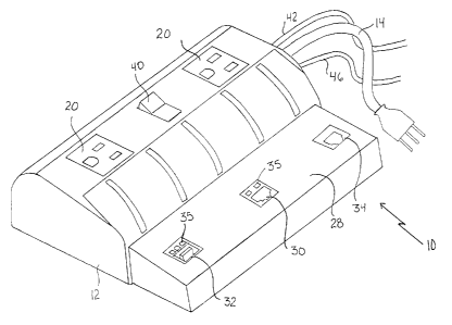
FIGURE 1 is a perspective view of an electric power bar
constructed in accordance with the teachings of the present
invention.
FIGURE 2 is a perspective view of the electric power bar
illustrated in FIGURE 1 connected to a computer.
FIGURE 3 is an end elevation view of the electric power
bar illustrated in FIGURE 1~
CA 02402542 2002-09-20
3
DETAI7~ED DESCRIPTION OF THE PREFERRED EI~ODIMENT
The preferred embodiment, an electric power bar
generally identified by reference numeral 10, will now be
described with reference to FIGURES 1 through g.
p
Structure and Relationship of Parts:
Referring to FIGURE l~ there is provided an electric
power bar 10, which includes a body 12. Referring to FIGURE
2, an electrical cord 14 is provided that is adapted to plug
body 12 into an electrical outlet 16 of a building 18.
Referring to GIGO ~,, body 12 has several female receptacles
which receive power via electrical cord 14. Referring to
FIGURE 2. each of female receptacles 20 is adapted to receive
a plug 22 from one of a computer 24 or ancillary equipment
1.5 such as a scanner 26 whereby power is supplied to computer 24
and scanner 26. It will be appreciated that instead of
scanner 26 other types of ancillary equipment such as
printers, or other external device requiring power can also
be plugged into one of female receptacles 20.
Referring to FIGURE 1. body 12 has a communications
module 28, whereby communications module 28 serves as a
conduit for sending and receiving messages. Body 12 has an
ethernet receptacle 30, an universal serial bus receptacle
32, and a telephone jack receptacle 34 in communication with
communications module 28, whereby computer 24 can be
connected in one of several different ways to communications
module 28. LED lights 35 indicate the operating status of
ethernet receptacle 30 and universal serial bus receptacle
32, as well as electric power bar 10. Referring to FIGURE 3,
communications module 28 also has a phone line in receptacle
36 and a phone line out receptacle 38. Referring to FIGURE
1, a power switch 40 is provided for turning power bar 10 on
and off.
CA 02402542 2002-09-20
4
Operation:
The use and operation of electric power bar generally
identified by reference numeral 10, will now be described
with reference to FIGS 1 through g. Electric power bar
10, as described above, is a more versatile and convenient
way to hook up computer 24 thereby eliminating the need for
numerous adaptors. Referring to FIGURE 2. power can be
i0 supplied to computer 24 and ancillary equipment such as a
scanner 26 by plugging computer and scanner into female
receptacles 20 of power bar 10. Communications module 28 of
electric power bar 10 is able t.o function as a home phone
network (HPN) ethernet bridge which enables computer 24 to
15 access communications networks through existing telephone
wires via communications module 28 of electric power bar 10.
As a result, the need to rewire network cables or share
network resources in building 18 is eliminated. Because
electric power bar 10 uses plug and play technology, no
?0 software configuration is required. Furthermore, electric
power bar 10 complies with most network protocols.
Referring to FIGS 2, to use electric power bar 10,
electrical cord 14 which supplies power to body 12, is
25 plugged into electrical outlet 16 of building 18. Power
switch 40 is switched to the on position. Plugs 22 from
computer 24 and from scanner 26 are plugged into each of
female receptacles 20 to supply power to computer 24 and
scanner 26, or if desired to other peripheral devices.
30 Telephone cord 42 from a telephone outlet 44 of building 18
is plugged into phone line in receptacle 36 illustrated in
FIGURE 3~ to allow communications module 28 to connect to
existing communications network. Referring to FIGURE 2~
Communications module 28 of electric power bar 10 permits
CA 02402542 2002-09-20
computer 24 to be connected to other communications networks
in a variety of ways. For example, computer 24 can be
connected to communications module 28 of electrical power bar
by plugging ethernet cable 52 from computer 24 into
ethernet receptacle 30 or by using a universal serial bus
cable 54 to connect computer 24 to universal serial bus
receptacle 32. Computer 24 is then able to access
communications networks through existing telephone wires via
communications module 28 of electric power bar 10.
10 If the user prefers to a dial up connection, a telephone
cord 50 can be plugged into a modem of computer 24 and then
plugged into telephone jack receptacle 34 of communications
module 28. Referring to FIGURE 2, furthermore, a telephone 48
can still be used for voice communications, by plugging a
cord 46 from telephone 48 into phone line out receptacle 38
illustrated in FIGURE 3~
While the illustrated embodiment shows communication
module 28 as having only one telephone jack receptacle 34,
ethernet receptacle 30, and universal serial bus receptacle
32, it will be appreciated that additional telephone jack
receptacles 34, ethernet receptacles 30, and universal serial
bus receptacles 32 could also be incorporated into
communications module 28 thereby enabling electric power bar
10 to have more versatility. This enhances the ways in which
computer 24 can be connected to communication networks or
ancillary devices. This is especially beneficial for setting
up home phone networks (HPN) and very high data rate digital
subscriber lines (VDSL). It is particularly suited to
buildings 18 such as hotels, where it is not cost effective
or practical to rewire for communications network access, as
with power bar 10, computer 24 is able to access
communications networks through existing telephone wires of
building 18 via communications module 28 of electric power
CA 02402542 2002-09-20
6
bar 10.
It will also be appreciated that with the increasing
popularity of wireless networks, phone line in receptacle 36
and a phone line out receptacle 38 could be replaced with
wireless components.
In this patent document, the word "comprising" is used
in its non-limiting sense to mean that items following the
word are included, but items not specifically mentioned are
not excluded. A reference to an element by the indefinite
article "a" does not exclude the possibility that more than
one of the element is present, unless the context clearly
requires that there be one and only one of the elements.
?5
It will be apparent to one skilled in the art that
modifications may be made to the illustrated embodiment
without departing from the spirit and scope of the invention
as hereinafter defined in the Claims.