Note: Descriptions are shown in the official language in which they were submitted.
CA 02404648 2002-09-27
WO 01/83132 PCT/SE01/00894
1
METHOD FOR MANUFACTURING OF A PLATE INVOLVING AN INTERMEDIATE
PREFORMING AND A FINAL SHAPING
TECHNICAL FIELD
The invention concerns a method for the manufacturing of a plate of metal or
of a
ceramic material, the plate comprising one or more fields which occupy the
major part
of the surface of the plate and which on at least one side of the plate is
high relief
patterned, more specifically patterned such that the plate on said at least
one side within
the area of said field or fields has reliefs with high projections and deep
valleys or
recesses alternatingly, and between the sides a thin web, said high relief
patterned field
or fields being at least partly bordered by broad edge portions which have a
thickness
larger than.the mean thickness of the plate within the region of said high
relief patterned
field or fields. Plates intended to be included in fuel cells or in heat
exchangers are
typical examples of plates of the above kind.
BACKGROUND OF THE INVENTION
It is difficult to manufacture metal plates of the above described kind, and
it is
extremely difficult to manufacture such plates which are thin and pronouncedly
high
relief patterned, at the same time as they are broad. Conventional methods,
such as
mechanical machining, spark machining, etching, laser working, etc. are slow
and
expensive and yet it is difficult to provide a perfect product with such
conventional
methods. This, to a high degree has impeded the development of fuel cells in
which
numerous high relief patterned plates are included. Such plates in a system
can contri-
bute e.g. to separate different gases, transport rest products, and conduct
generated
current in the fuel cell system and usually have a circular, square or
rectangular shape
with a central field, which on both sides have grooves, which are separated
from one
another by relatively high tongues. These high relief patterned fields are
surrounded by
a circumferential, comparatively broad edge, which forms a flat frame around
the high
relief patterned central field, the top planes of the tongues coinciding with
the two side
planes of the frame. The thickness of such plates may vary quite considerably
from case
to case but does not normally exceed 3 mm, while the thickness of the web
between the
grooves may amount e.g. in the order of 1 mm: A method of producing the
grooves in
the plates according to today's technique is by any kind of machining but that
is as
mentioned a slow and expensive process. It is not possible to cause the
material to flow
out completely in the tool mould through conventional moulding technique,
because
considerable friction forces prevent the transportation of material. If, on
the other hand,
higher pressures were applied in conventional equipment for the provision of
necessary
transportation of material in order to cause the material to completely fill
the tool
CA 02404648 2002-09-27
WO 01/83132 PCT/SE01/00894
2
mould, the tools may be damaged. Similar problems exist in the manufacturing
of plates
intended to be included in heat exchangers.
DISCLOSURE OF THE INVENTION
It is the purpose of the invention to provide a considerably more convenient
process for
the manufacturing of metal plates of the type mentioned in the preamble,
particularly
metal plates for fuel cells and/or for heat exchangers. More particularly the
invention
aims at providing a manufacturing technique which is considerably cheaper than
conventional technique but which nevertheless provides a product which
satisfies the
very rigorous demands in terms of dimensional accuracy, density and other
features
which are raised about fuel cell plates and heat exchanger plates. The method
of the
invention, however, is not restricted only to manufacturing of fuel cell
plates and heat
exchanger plates but can also be widely used for other metal plates, in
particular plates
which are broad in relation to their thickness.
According to the invention a moulding technique is used, employing high
kinetic energy
for the manufacturing of the plate with the high relief patterned sides. But
it is not
possible to manufacture plates with that pattern by high kinetic energy
forming by a
single stroke when starting from powder or from a flat plate. Even if the
material is
softened by the very high pressure that is generated at the high kinetic
forming, the
ability of the material will nevertheless be too restricted to flow not only
in the
labyrinth-like passages in that part of the moulding tool that shall form the
high relief
pattern, but also to flow out to the thicker edge portions. Nor is it possible
in the same
tool to form the product through a series of strokes. To the contrary, the
problems would
be accentuated. This is particularly true when starting from a powder, which
certainly
can be plasticised in a surface layer at the first impact. But that would
instead make the
plasticising of the powder further down in the powder bed more difficult,
resulting in a
very inhomogeneous compacting and increased friction.
The principle of the invention therefore is to first manufacture an
intermediate product
suitable for a final forming operation based on"forming the high relief
patterned plate in
a single stroke through the supply of very high kinetic energy.
According to the invention an intermediate product is manufactured in at least
one
preliminary step, the intermediate product comprising a first portion which
shall form
said high relief patterned field(s), which however is(are) not yet high relief
patterned but
contain(s) a quantity of material essentially corresponding to the quantity of
material
CA 02404648 2002-09-27
WO 01/83132 PCT/SE01/00894
3
existing within said field(s) of the finished plate, and second portions which
shall form
said edge portions and which contain substantially the quantity of material
that shall
exist in.the edge portions of the finished plate. This intermediate product is
placed
between at least two engraved moulding tool parts, which are movable relative
to one
another, at least one of said moulding tool parts being high relief embossed
and at least
one being a punch, said tool parts, when they are maximally brought together,
forrning
between them and/or together with at least one or more tool parts, a mould
cavity
corresponding to the final shape of the finished plate within the regions of
said high
relief patterned field(s) and at least near the final shape of said edge
portions. Then the
high relief pattern within the region/regions of said field(s) is/are
established by striking
the engraved tool parts against one another, at least said punch being
stricken against
said intermediate product wherein the material within the regions of said at
least one
first portion is caused to flow and fill the mould cavity to establish said
high relief
pattern essentially without transportation of material between said first and
second
portions.
In order to strike the engraved tool parts against one another one or two,
respectively,
rams can be used which preferably are hydraulically powered, which are
stricken
against the punch, or the punches, respectively, which in turn transmit(s) the
kinetic
energy to the intermediate product. The punches and impact members in this
case thus
are separate units, wherein the impact members can consist of e.g. hydraulic
impact
pistons. It is however possible, that the impact members and the punches are
integrated
units. This may particularly be true when the stroke is performed from above,
wherein
the impact member, e.g. a hydraulic piston, is united with the punch which
from above
is stricken down into a die. The punch in this case is an elongation of the
piston rod of
the impact piston. The same condition in principle can also be conceived in
the case
when the impact machine comprises also a lower punch which e.g. via a lower
punch
holder may be united with a lower impact member, which also may consist of a
piston.
According to this modification, the acceleration of the punches during the
strike
preferably takes place within the through-hole in said at least one further
tool part,
which preferably is a die, containing the cavity in which the moulding work
takes place.
By employing a very high impact action in the final forming operation through
a single,
very powerful strike on the working material from one direction, or from two
opposite
directions, a pressure is generated which has a very short duration but is so
high that the
working material is plasticised and fills the mould cavity, so that the
material will flow
out to all parts of the mould cavity considerably more efficiently, probably
because of
CA 02404648 2002-09-27
WO 01/83132 PCT/SE01/00894
4
lower friction, than in a conventional press operation, which is based on the
employ-
ment of very high forces. The technique which implies forming with high, or
more
correctly, adequate kinetic energy of movable tool parts, causes the material
to
plasticise, and therein possibly also causes the lower friction to arise,
which allows the
material to be formed plastically at a rate which may be 10-100 times higher
than/
according to conventional forming technique.
According to performed measurements and calculations, the pressure pulse
generated at
said single impact has a duration which is less than 0.001 sec. but a
magnitude which
10, lies in the range 1-10 GPa. Typically the range is 1.5-5 GPa. Because of
the high
pressure and the plasticising caused by the high pressure, probably the low
friction
between the working material and the walls of the mould cavity,is also
obtained, as well
as between the powder grains when the working material consists of a powder
(can be
applied at the manufacturing of the intermediate product), which contributes
to or is a
prerequisite for the ability of the working material to flow out and fill all
parts of the
mould cavity.
The starting material for the manufacturing of the intermediate product is
either a
ceramic powder or a metal powder or a homogenous ceramic or metal plate, which
can
be manufactured in a conventional way, e.g. by punching out of a larger plate,
or by
compacting and sintering a powder, or in any other way involving powder
technique for
the achievement of a homogenous plate with even thickness. At least when
starting from
a homogenous plate, the manufacturing of the intermediate product may aim at
pressing
out material to the outer edges of the plate. Whatever technique that is used,
the
objective of manufacturing the intermediate product is to provide an
intermediate
product in which a proper quantity of material exists at the right place, i.e.
in the region
of said field(s) and said edge portions, respectively, when performing the
final forming
operation, when the plate is formed between the engraved moulding tool parts
under a
very high pressure of very short duration as above described, so that the
plate obtains
said high relief pattern within the region of the centre field, i.e. is formed
with grooves
and tongues when it concerns manufacturing fael cell plates. At the final
forming
operation, when the material is caused to flow because of plasticising under
very high
pressure, the porosity which possibly exists in the intermediate product when
starting
from a powder, can also be eliminated, so that a density is achieved,
sufficient for the
function of the plate, e.g. in a fuel cell. As an alternative the porosity can
be eliminated
by sintering the final formed plate in a subsequent operation. According to
still another
alternative the porosity is eliminated already in the intermediate product by
sintering the
CA 02404648 2002-09-27
WO 01/83132 PCT/SE01/00894
intermediate product, i.e. heating it to an adequate temperature for fusing
existing pores
in the material before the plate is subjected to final forming. Also a
combination of
these alternatives can be conceived.
5 In connection with the manufacturing of the intermediate product, a green
body can be
manufactured powder metallurgically, which body, as above mentioned, suitably
is
sintered by heating, so thatthe powder grains coalesce to form an essentially
consoli-
dated body suited for the subsequent final forming by bringing engraved tool
parts
against one another with such high kinetic energy that the material will
plasticise
according to above. It is also conceivable to manufacture the intermediate
product by
pressing powder in a tool, which comprises at least one punch which is
stricken with
high kinetic energy against the powder, wherein the kinetic energy of the
punch is so
high and to such a high degree is transferred to the powder that the powder
will
plasticise to such a high degree that the intermediate product will be
sufficiently
consolidated to be used as an intermediate product for the final forming
operation. It is
also conceivable to form a green body or consolidated body by pressing in a
plurality of
steps.
In order to facilitate the pre-compacting of the powder to a well united or
consolidated
body in connection with the manufacturing of the intermediate product when
starting
from a metal powder, it might be advantageous to preheat the powder to at
least 70 C
before the press operation or press operations, respectively. This
particularly applies
when said metal consists of a light metal, preferably any of the metals
belonging to the
group consisting of aluminium, magnesium, and titanium, or of an alloy which
substan-
tially consists of one or more of said metals. Typically, fuel cell plates are
made of such
metal. For the manufacturing of plates of other metals, such as brass or
steel, including
stainless steel, the starting material, whether it is a powder or a homogenous
plate,
should be preheated to a higher temperature.
The intermediate product can also be manufactured from a homogenous metal
plate by
conventional machining, such as for example inilling or grinding in order to
establish
said first portion or portions having a smaller thickness than the edge
portions, i.e.
ensure "right quantity of metal on the right place" for the subsequent final
forming by
means of high kinetic energy, when the high relief pattern is established.
In connection with the forming operation or operations which include movements
of
tool parts with sufficiently high kinetic energy relative to one another,
lower tool parts
CA 02404648 2007-10-12
6
can be provided on an anvil which is stationary or movable upwards during the
forming
operation, while upper tool parts, which are accelerated to obtain a
sufficiently high
kinetic energy are stricken downwards against the lower tool part or tool
parts, wherein
devices preferably are provided to dampen or to eliminate the shock wave which
other-
wise is developed in the impact machine that is used. For example any of those
impact
machines which are described in the Swedish patent applications 0001558-6,
0001660-
2, 0002030-5 and/or 0003279-7 filed by the same applicant, may be used,'
These
machines are particularly well suitable for the final forming of fuel cell
plates and heat
exchanger plates, comprising so called high kinetic energy shaping, but can
advan-
tageously also be used for the manufacturing of the intermediate product also
in the case
also that manufacturing comprises forming of the type employing supply of
adequate
kinetic energy for the establishment of a pressure pulse having a very short
duration but
a very high magnitude.
One can also conceive that the engraving of the sides of the metal plate is
carried out by
means of separate tool parts in connection with the forming of the
intermediate product
from powder as well as in connection with the final forming of the high relief
patterned
plates. For example a central punch and a first ram, which possibly may be
integrated,
can be used for the central field or fields -which shall be high relief
patterned, and one or
more circumferential punches and one or more second rams, which may also
possibly
be integrated, and/or may be used to form the circumferential, frame shaped
edge
portion. This principle gives an opportunity to supply most k.inetic energy to
the region
where the requirements as far as good flowability are highest, i.e. the
central field or
fields which shall be high relief patterned.
In impact machines a technique is employed which often is referred to as high
velocity
forming, because high velocities of the rams in impact machines generally have
been
considered to be a requirement for the achievement of desired results as far
as the
forming work is concerned. High velocities of the moving units, however, can
involve a
complication, if the machine works according `to the counter striking
principle, i.e. with
units which move towards one another during the impact operation. The
complication
lies in the fact that the movements of the units which are movable against one
another
must be synchronized and coordinated with great accuracy in terms of velocity
(impulse) and position in order that the stroke shall be performed
simultaneously with
correct impulse of the masses which move against one another, something which
becomes increasingly difficult the higher the velocities of the moving parts
are.
CA 02404648 2002-09-27
WO 01/83132 PCT/SE01/00894
7
An aspect of the invention is based on the consideration that the velocities
of the
movable units in the impact machines, which move against one another during
the
impact operation, need not at all be as large as has been considered necessary
in view of
prior art. Nor should the kinetic energies need to be correspondingly high,
i.e. lower
velocity shall not necessarily need to be compensated by correspondingly
larger
movable masses. With the same masses, according to this aspect of the
invention, the
velocity thus can be reduced in the order of 5 to 10 meters per sec. of said
rams to the
order of 1 meter per sec., or more generally 0.5-2 meters per sec.
The lower velocities thus improve the possibility of synchronizing the
movements of the
movable units during the impact operation. Even though the velocities are
radically
reduced, the forming work nevertheless can be perfect, whether the working
material is
a powder or a solid body. Without binding the invention to any specific
theory, it can be
assumed that this is due to the good synchronization of the counter directed
movements,
which in turn has the result that the kinetic energy of the moveable masses
essentially
can be used as effective forming work with small losses of energy to the
machine
foundation and stand.
Another favourable effect with the lower velocities of the units that are
movable
20, towards one another, is that the ram travels can be shortened. This makes
it possible to
design the impact devices/the rams and the punches to form integrated units,
as above
mentioned. The punches in this case may be inserted into the upper and lower
openings,
respectively, of the die in the starting position for an impact operation,
even if the
punches are integrated with the impact devices/rams or corresponding, wherein
the ram
travels, i.e. the acceleration lengths, will be shorter than the axial length
of the mould
cavity of the die.
It shall thus be understood that the expressions high kinetic energy or very
high kinetic
energy are relative conceptions and shall be interpreted to mean adequate
kinetic energy
for the achievement of the effect in terms of forming work, which has been
mentioned
in the foregoing and which will be described more in detail in the following,
detailed
description of the invention.
Further characteristic features and aspects of the invention as well as
advantages will be
apparent from the appending patent claims and from the following description
of an
embodiment.
CA 02404648 2002-09-27
WO 01/83132 PCT/SE01/00894
8
BRIEF DESCRIPTION OF THE DRAWINGS
In the following description of an embodiment of an invention, reference will
be made
to the accompanying drawings, which schematically illustrate the manufacturing
of a
fuel cell plate, wherein
Fig. 1 schematically shows the tool parts for the manufacturing of an
intermediate
product,
Fig. 2 shows a portion of Fig. 1 at a larger scale,
Fig. 3 shows the tool parts for the manufacturing of the final product,
Fig. 4 shows a portion of Fig. 3 at a larger scale,
Fig. 5 shows the principle shape of the intermediate product in a cross
section, and
Fig. 6 shows the principle shape of the final product, a metal plate for fuels
cells, in
cross section.
DESCRIPTION OF PREFERRED EMBODIlVIENT
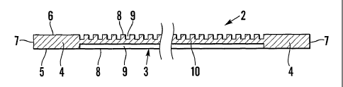
With reference first to Fig. 5 and 6, an intermediate product is designated 1,
and
schematically shown in cross section, a metal plate for fuel cells is
designated 2. The
plate 2, which is substantially square, consists of a central field 3, which
occupies the
major part of the surface of the plate, and edge portions 4, which are broad
in compa-
rison with the thickness of the plate and,surrounds the whole field 3 as a
frame. The
edge portions 4 have flat broad surfaces 5, 6. The outer sides are designated
7. The
centre field 3 according the embodiment is high relief patterned on both sides
(also
single sided high relief patterning can be conceived in some cases) and
displays alter-
natingly tongues 8 and grooves 9. The tongues and grooves 8, 9 on the upper
side
according to the embodiment are at a right angle or at the nearest right angle
to the
tongues and grooves on the bottom side. Between the grooves 9, i.e. between
the two
sides of the plate, there is a thin web 10. The tops of the tongues 8
according to the
embodiment are level with the broad surfaces 5, 6 of the edge portions.
The intermediate product 1 consists of a central, first portion 11, which in
the finished
product shall form the high relief patterned field 3, and around said'first
portion 11
circumferential portions 12, which shall form said circumferential portions or
frame 4 of
the finished plate 2.
The objective of the manufacturing of the intermediate product 1 is to shape a
consoli-
dated and essentially homogeneous intermediate product, the central portion 11
of
which contains the metal quantity that shall form the high relief patterned
central field 3
of the finished product 2. Possibly a very small surplus of metal can be
tolerated in the
CA 02404648 2002-09-27
WO 01/83132 PCT/SE01/00894
9
central portion 1, which according to the embodiment is completely flat. Also
the side
portions 12 of the intermediate product 1 shall contain the metal quantity
that shall be
present in the outer portions 4 of the finished product 2. A certain surplus
of metal in the
portions 12 can be tolerated, if the final shaping of the product 2 is
performed in such a
way that the surplus can be caused to flow out to form "burr" or
corresponding, which
can be removed in a skegging operation after completed compression moulding.
The tool parts shown in Fig. 1 and Fig. 2 can be used for the manufacturing of
the
intermediate product 1. The three moulding tool parts consist of a counter
punch 20, a
punch 21, and a die 22. The latter is shown in cross section. The die
sealingly surrounds
the upper part of the counter punch 20 and also works as a guide for the punch
21
during the operation of the punch. The surfaces of the counter punch 21 and of
the
punch 20 which face one another may have equal gravures 23 designed so that
the two
broad sides of the intermediate product 1 are congruent reproductions of the
gravures
23. This in other words means that the counter punch 20 and the punch 21 have
a flat
central portion 24 for forming the central portion 11 of the intermediate
product I and a
circumferential recess 25 for forming the frame 12 of the intermediate product
1.
When the intermediate product 1 shall be manufactured, an accurately measured
quantity of metal and/or ceramic powder is charged into the space 26 defined
by the die
22 and the countei- punch 20, in which space the counter punch 20 forms a
bottom and
the die 22 forms a wall. As an alternative, a flat plate can be used as a
starting material
for the manufacturing of the intermediate product 1. Also such a plate shall
contain the
same quantity of material as in the desired intermediate product 1 and
preferably has an
outer shape corresponding to the shape of the die 22. Whether powder or a
solid body is
used as a starting material, it can be suitable to preheat it before the
forming operation,
as has been mentioned in the initial disclosure of the invention.
The counter punch 20 and the die 22 are provided in a not shown tool housing,
which is
placed on a stationary or movable anvil. The punch 21 is brought down into the
hole in
the die 22 so far that it will contact the powder or the homogeneous plate,
respectively.
When it is regarding a powder, the punch 21 is pressed with some power against
the
powder, so that the powder grains are subjected to a slight pressure, such
that they will
orient themselves for the achievement of a certain close-packing of the powder
bed in
the mould cavity which is defined by the two gravures 23 and the die 22. Then
a ram,
i.e. an impact piston in an impact machine, is stricken with very high kinetic
energy
against the upper side of the punch 21, suitably via an impact body resting
against the
CA 02404648 2002-09-27
WO 01/83132 PCT/SE01/00894
punch and transfers the impact energy of the ram to the. punch. The very high
impact
energy is transferred to the powder in the mould cavity, so that the powder
grains
plasticise and the plasticised powder in a few microseconds form a
consolidated body
having the desired shape of the intermediate product 1. During this high
kinetic energy
5 moulding, a certain flow of the material that is plasticised during the
impact may occur
between the portions 11 and 12.
The punch 21 then is lifted up again and the formed intermediate product 1 is
pushed
out of the die 22, suitably through a relative movement between the die 22 and
the
10 counter punch 20.
In the case when the counter striking principle is applied, as according to
the disclosure
of any of the Swedish patent applications 0001558-6 or 0002030-5, wherein the
counter
punch 20 is stricken upwards in the die synchronously with the punch 21 being
stricken
downwards, and with the same momentum of the movable parts, the forming work
is
rendered more effectively therein that the kinetic energies to a higher degree
are trans-
ferred to the product to be formed than in the case when the counter punch 20
is station-
nary. In this case the velocities need not be as high as when only the punch
is subjected
to impact action. When employing the counter striking principles, the movable
parts
thus are accelerated to obtain an adequate kinetic energy, which need not
necessarily be
extremely high.
In order to ensure that the intermediate product 1 is completely consolidated,
it should
be sintered prior to the final forming of finished product 2. This is
particularly important
if the intermediate product is not formed through the supply of a very high
kinetic
energy; which creates a pressure pulse with a high magnitude of a short
duration, but
through a more conventional compression moulding, which provides a green body
with
smaller strength.
The moulding tool parts for forming the finished plate 2 are designed in a way
that is
analogous with the tool parts for the manufacturing of the intermediate
product 1 and
comprise a counter punch 30, a punch 31 and die 32, wherein the counter punch
30 and
the punch 31 have engravings 33 which are congruent with the broad sides of
the
finished product 1. Thus the engraving 33 of the counter punch 30, for
example, has a
central portion 34 with projections which shall form the grooves 9 of the high
relief
pattern of the central field 3 of the finished metal plate 3, which grooves
shall form one
or more passages in the plate, and recesses, which shall form the tongues 8
between said
CA 02404648 2002-09-27
WO 01/83132 PCT/SE01/00894
11
recesses/channels 9. Around this profiled central portion 34 there is a
circumferential
portion 35, which is flat and level with the bottom of the recesses of the
central portion
34, so that the two flat sides 5, 6 of the circumferential edge portion 4 will
be at level
with the top of the tongues 8 of the finished plate 2.
The intermediate product 1 is placed on the counter punch 30 in the space 36
in the die
32. The punch 31 is lowered to rest on the intermediate product 1. Possibly
the inter-
mediate product 1 is preheated before an impact member with a very high
kinetic
energy is stricken against the upper side of the punch 31. The impact energy
is trans-
ferred to the intermediate product 1 which is plasticised. The material in the
central
portion 11 flow out to form said tongues 8 and grooves 9, i.e. the high relief
embossing
of the region of the centre field 3. At the same time the edge portions 4 are
also formed
to their final shape and when that is needed, pores in the material are
eliminated, so that
the finished plate 3 will be very dense. Any essential transport of material
between the
central portion 11 and the edge portions 12 does not take place during this
final forming
operation. Any possible excess of metal in the edge portions 12, Fig. 5, may
be allowed
to flow out beyond the end sides 7 that are formed by the die 32, which may be
designed with not shown expansion spaces for such minimal metal flow. The
"burr"
which thus can be formed to a very little extent can be removed in a final
skegging
operation, when the formed plate 2 has been pushed out from the tool. Also in
connec-
tion with this final moulding operation the above mentioned counter striking
principle
can be applied, i.e. that the punch 31 and the counter punch 30 simultaneously
are
stricken against one another with equal momentums, wherein the velocities of
the
moving tool parts need not be as high as when the punch 31 is stricken against
a
stationary counter die, however need be adequate for the achievement of the
desired
plasticising of the intermediate product, so that the material in the central
portion 11
will flow out to form said tongues 8 and grooves 9, i.e. the high relief
pattern in the
region of the central field 3.