Note: Descriptions are shown in the official language in which they were submitted.
CA 02404845 2002-10-28
-1-
VOLUMETRIC INFUSION PUMP
FIELD OF THE INVENTION
The instant invention relates to volumetric infusion pumps for
s parenteral delivery of fluids in a medical environment.
BACKGROUND OF THE INVENTION
Previous medical infusion pumps have comprehended a wide variety
of methods for pumping fluids into a patient. The most common of these
Io methods has been a peristaltic pump. In a peristaltic pump, a plurality of
actuators or fingers serve to massage a parenteral fluid delivery tube in a
substantially linear progression. The primary problem associated with
peristaltic pumping technology is that the tube is repeatedly deformed in an
identical manner, thereby over the course of time destroying the elastic
is recovery properties of the tube so that the tube maintains a compressed
aspect. This destruction of the elastic recovery properties of the tube
results
in the volumetric output of the pump changing markedly over time. Another
common type of pump used in the volumetric delivery of medical fluids is
commonly known as a cassette pump. Although cassette pumps do not
2o display the fairly rapid degradation of performance as evidenced in a
peristaltic pump, they require a fairly elaborate pump cassette to .be
integrated with the IV tube. This added expense of having to change a
cassette along with an IV set every time an operator wishes to change the
medicament delivered to the patient, significantly raises the cost of patient
25 care. Additionally, as both peristaltic and cassette pumps, as well as
other
infusion devices present in the market, require a fairly elaborate knowledge
of the specific pumping device to ensure that the IV set is loaded
CA 02404845 2002-10-28
-2-
appropriately, generally medical infusion pumps were purely the purview of
the nursing or medical staff in a hospital environment.
The necessity of manually loading a set into an IV pump is universal
in the art. Generally when a standard IV set is used, in addition to the rapid
degradation of accuracy mentioned above, great difficulty is encountered in
correctly loading the set into those pumps presently in the art. The state of
the art of loading technology as it relates to medical infusion pumps has
progressed only to the state of enclosing the IV tube between a pumping
device and a door or cover and adding progressively more elaborate sensors
io and alarms to assure that the tube is correctly loaded into the pump. Even
so, loading errors occur with regularity requiring great efforts on the part
of
hospital staffs to ensure that critical errors are minimized.
The state of the art in infusion pumps also includes the requirement
of manually assuring that a free-flow condition of medicament does not
~s occur when an IV set is installed or removed from a pump. Although
hospital staffs exercise great care and diligence in their attempts to assure
that free-flow conditions do not occur, a demonstrable need for additional
precautions directed to the prevention of a free-flow condition has been a
continuous concern of healthcare workers.
2o U. S. Patcnt 5,199, 852 to Danby discloses a pumping arrangement
including a squeezing device for deforming a length of pliant tubing first in
one direction locally to reduce its volume, and in another direction tending
to restore its original cross-section and on either side of the squeezing
device, inlet and outlet valves which operate by occluding the tubing. The
25 control of the valves is by a plurality of motors controlled by a micro-
processor.
U.S. Patent 5,151,091 to Danby et al. discloses a pumping device
which alternately compresses and reforms a section of tubing.
CA 02404845 2002-10-28
-3-
U.S. Patent 5,055,001 to Natwick et al. discloses an infusion pump
with spring controlled valves designed to open at a specific predetermined
pressure.
U.S. Patent 3,489,097 to Gemeinhardt discloses a flexible tube pump
s having a unitary fixture operative to act as an inlet and outlet valve and a
pumping body located therebetween, driven off an eccentric.
U.S. Patent 2,922,379 to Schultz discloses a mufti-line pump having
an inlet and an outlet valve mechanism and a pumping body located
therebetween whertin both the inlet valve mechanism and the outlet valve
1o mechanism are driven from a single cam.
U.S. Patent 3,359,910 to Latham discloses a cam driven pump
having inlet and outlet valves driven from a single cam and a pump body
driven by an eccentric co-rotating with the single cam.
U.S. Patent 4,239,464 to Hein discloses a blood pump having an
~s inlet and outlet plunger serving as valves and a displacement plunger
located
thcrebetween.
U.S. Patent 5,364,242 to Olson describes a drug pump having at
least one rotatable cam and a reciprocally mounted follower engaged with
the cam in a tube which is compressed by the follower during rotation of the
2o cam. In the embodiment disclosed there are three cams.
U.S. Patent 5,131,816 to Brown et al. discloses a infusion pump
containing a plurality of linear peristaltic pumps and includes a position
encoder mounted on the pump motor shaft to determine when the shaft has
reached the stop position in the pump cycle.
25 U.S. Patent 4,950,245 to Brown et al. discloses a multiple pump
which is individually controlled by a programmable controller within the
pump.
CA 02404845 2002-10-28
-4-
U.S. Patent 4,273,121 to Jassawalla discloses a medical infusion
system including a cassette and a deformable diaphragm and inlet and outlet
windows which are occludable to pump the fluid contained in the cassette.
U.S. Patent 4,936,760 to Williams discloses a infusion pump adapted
s to use a special tube wherein the tube has diametrically opposed handles
extending longitudinally thereon and wherein the handles are adapted to be
gripped by pump actuators so as to deform the tube transversely by pulling
or pushing on the handles.
U.S. Patent 5,092,749 to Meijer discloses a drive mechanism for
to actuating the fingers of a peristaltic pump having a jointed arm pivotally
attached at one end to a drive member and at the other end to a fixed point
on the base of the pump and a rotary cam actuator mounted on the base to
urgt against the arm and reciprocate the drive member.
U.S. Patent 4,850,817 to Nason et al. discloses a mechanical drive
is system for a medication infusion system comprising a cassette pump wherein
inside the cassette a single cam drives the inlet and outlet valves as well as
the pump mechanism.
U.S. Patent 5,252,044 to Raines discloses a cassette pump.
U.S. Patent 3,606,596 to Edwards discloses a drug dispensing pump.
2o U.S. Patent 3,5I8,033 to Anderson discloses an extracotporeal heart.
SUMMARY AND OBJECTS OF THE INVENTION
The instant invention provides for an infusion pump wherein the
pump has a pumping body which consists of a v-shaped groove extending
25 longitudinally along a pump assembly and has associated therewith a fixed,
and a moveable jaw and a plurality of valves located at either end of the v-
shaped groove or shuttle.
CA 02404845 2002-10-28
-5-
In operation, an operator such as a nurse or patient would commence
infusion of a medicament by inserting a standard IV set tube into a tube
loading orifice located on the front of the pump. Additionally, the operator
would simultaneously insert a slide clamp which is associated with the tube
into a appropriate slide clamp orifice located upstream, i.e. more toward the
fluid source, of the tube loading orifice. The operator would then actuate a
tube loading sequence in which a series of pawls and a moveable upper jaw
would serve to seize the tube and draw it into a tubeway, part of which is
comprised of the v-shaped groove and valves. As the loading cycle
~o progresses the jaws and pawls close about the tube capturing the tube
within
the tubeway. Sequentially as the valves close to occlude the tube, the slide
clamp would be moved to a position such that the slide clamp would no
longer occlude the tube. Upon receipt of appropriate signals from associated
electronics which would determine the pumping spend, allowable volume of
air, temperature and pressure, the pump is actuated wherein fluid is drawn
from the fluid source and expelled from the pump in a constant and metered
amount.
Should the tube be misloaded into the tubeway or the tubeloading
oriftce, appropriate sensors would determine the existence of such a state and
2o effect an alarm directed thereto.
At the end of the infusion, actuation by an operator would serve w
automatically close the slide clamp and release the tube from the pump.
The pump comprehends a variety of sensors directed to improve the
safety of the infusion of medicament in addition to the sensors recited
2s previously which provide information on the state of the fluid passing
through the pump, the pump comprehends a variety of sensors operative to
provide information regarding the state of various mechanical subassemblies
within the pump itself. Among the sensors are devices directed to providing
CA 02404845 2002-10-28
-6-
positional location of the shuttle or v-shaped slot aforementioned, valve
operation,
slide clamp location, misload detection, and manual operation of the
tubeloading
assembly.
The sensors relating to the state of the fluid being passed through the pump
have themselves been improved with regard to accuracy. This has been
accomplished
by the development of the method of making contact between the sensor and the
tube
such that the contact is normal to the tube and the tube is placed in contact
with the
various sensors in such a way that there is neither a volumetric nor a stress
gradient
across the tube.
Therefore, it is an object of an aspect of the invention to provide for an
infusion pump capable to delivering an accurate volume of medicament using a
standard infusion set.
It is another object of an aspect of the invention to provide an infusion pump
having a pumping shuttle and valves associated therewith, wherein the pumping
shuttle and valves are mechanically synchronized.
It is a further object of an aspect of the invention to provide an infusion
pump
having greatly improved accuracy whereby the output of the pumping member is
linearized over the course of a pumping cycle.
It is another object of an aspect of the invention to provide for a plurality
of
valves in an infusion pump such that the valves are adapted to occlude an
infusion set
tube while having a shape adapted to promote the elastic recovery of the tube
when
the valve is released therefrom.
It is an additional object of an aspect of the invention to provide an
infusion
pump having enhanced resistance to medication errors by providing for an
automatically loaded slide clamp associated with the infusion set.
It is a further object of an aspect of the invention to provide, in the
aforementioned infusion pump having a resistance to medication errors, a slide
clamp
sensor operative to sense whether the slide clamp aforementioned is opened or
closed.
It is an additional object of an aspect of the invention to provide for a
synchronized, automatic closure of the slide clamp at all times when a free
flow of
medicament is possible.
It is an additional primary object of the invention to provide for an infusion
CA 02404845 2002-10-28
_'J_
pump capable of automatically loading a standard IV set therein.
It is a further object of an aspect of the invention to provide for an
infusion
pump capable of sensing an incorrectly automatically loaded IV set and further
capable of releasing the set from the pump in a state operative to prevent
free flow of
medicament through the set.
It is another object of an aspect of the invention to provide an
autotubeloader
assembly operative to automatically load and unload a standard IV set from an
associated infusion pump.
It is an additional object of an aspect of the invention to provide for a
synchronization of the slide clamp state and the valve state such that when
one of the
valves is in an open state, the second of the valves is in a closed state and
when both
valves are in an open state, the slide clamp is in a closed state.
It is an additional object of an aspect of the invention to provide for a
partial
cycle of the pumping member immediately subsequent to the tubeloading cycle,
so as
to ensure that the tube is properly seated in the pumping member
aforementioned.
It is another object of an aspect of the invention to provide a cam associated
with the pumping member wherein the cam is operative to linearize the output
of the
pump.
It is a further object of an aspect of the invention to provide for a
variability of
pumping speed over the course of a pumping cycle.
It is another object of an aspect of the invention to provide a further
linearization of pump output by varying the speed of the pumping member.
It is an additional object of an aspect of the invention to provide a
variability
in pumping output over the course of an infusion by varying the speed of the
pumping
member.
It is a further object of an aspect of the invention to provide for a
hydrodynamic assistance in the elastic recovery of the tube during the fill
portion of a
pumping cycle.
It is another object of an aspect of the invention to provide a pumping body
having an aspect adapted to be assembled with other pumping bodies into a
multiple
channel pump having a single controller.
It is a further object of an aspect of the invention to provide for a
tubeloading
CA 02404845 2002-10-28
_f_
assembly having pawls adapted to capture and restrain an IV tube within the
pump.
It is another primary object of an aspect of the invention to provide for a
sensor housing and an actuation assembly associated with the housing adapted
to
place a sensor in substantially normal contact with the tube.
It is an additional object of an aspect of the invention to provide for a
sensor
housing and an actuation assembly operative to place a sensor in contact with
a tube
such that the volumetric gradient across the tube beneath the sensor is
essentially zero.
It is a further object of an aspect of the invention to provide for a sensor
housing and an actuation assembly operative to place a sensor in contact with
a tube
such that the stress gradient of the tube beneath the sensor is essentially
zero.
It is another object of an aspect of the invention to provide for a single
datum
body operative to fix the relative location of the various elements within the
pump.
It is a further object of an aspect of the invention to provide for a
plurality of
1 S shafts associated with the single datum body and cooperative therewith to
fix the
relative location of the various elements of the pump.
It is an additional object of an aspect of the invention to provide a compact
means for pumping a medicament.
It is a further object of an aspect of the invention to provide for a fluid
seal
barrier operative to prevent fluid ingress to various electrical components of
the
pump.
It is another object of an aspect of the invention to provide for a case
having a
geometry operative to enforce a downward orientation of the tube in those
areas
exterior to the pump.
It is a further object of an aspect of the invention to provide for manual
means
for actuating the automatic tube loading feature.
According to one aspect of the invention, there is provided an infusion pump
operative to pump a fluid through a segment of tubing having a longitudinal
axis
defined thereon, said pump comprising a means for pumping said fluid and a
means
for automatically loading said segment of tubing, substantially transversely
to said
longitudinal axis, into said pump.
According to another aspect of the invention, there is provided an automatic
loading apparatus associated with an infusion pump and a tube for use in said
pump,
CA 02404845 2002-10-28
-9-
said automatic loading apparatus comprising a pawl operative to releasably
grip and
retain said tube and a cam operative to actuate said pawl.
According to a further aspect of the invention, there is provided an automatic
S loading apparatus for loading a fluid carrying tube into an infusion pump
wherein said
loading apparatus has associated therewith a platen and a loading pawl having
a tip,
said tip having defined thereon a tube rejection surface, a misload activating
surface, a
tube capture surface, an angled engaging surface and a horizontal engaging
surface
about a periphery.
According to another aspect of the invention, there is provided an infusion
pump having an automatic tubeloading apparatus associated therewith, said
automatic
tubeloading apparatus having a pawl, said pawl being extensive from a
layshaft, a jaw
carrier associated with said layshaft and co-rotational therewith, said jaw
carrier
having a cam follower arm and a positional sensor on said cam follower arm, a
spring
loaded cam follower associated with said cam follower arm, a cam in sliding
contact
with said cam follower and an encoder operative to provide positional
information of
said cam, said pawl having a tube compressing tip portion and a platen
cooperative
with said tube compressing tip portion to compress a tube therebetween; the
method
of detecting a misload of said tube into said pump comprising the steps of:
a) wherein said tube is positioned between said tube compressing tip
portion and said platen, compressing said tube;
b) wherein said spring loaded cam follower and said cam follower arm
define an interstice therebetween, rotating said cam so as to close said
interstice;
c) wherein said encoder has an output indicative of the position of said
cam, wherein said cam has a plurality of positions, determining the change of
position
of said cam as said interstice is closed;
d) wherein said sensor has an output capable of change and wherein said
change is indicative of the position of said jaw carrier wherein said jaw
carrier has a
plurality of positions noting the tack of change of position of said jaw
carrier as said
interstice is closed;
e) comparing the outputs of the encoder and the sensor to determine that
the interstice is being closed as the pawl is prevented from moving due to its
enVagement with said tube;
CA 02404845 2002-10-28
-9a-
f) wherein said outputs have associated therewith an alarm, actuatin~~ said
alarm;
g) wherein said cam has a motion which can be reversed, reversing the
motion of said cam; and
h) by co-action of said cam, cam follower, jaw carrier, layshaft, pawl and
tube compressing tip portion, releasing said tube from beneath said tip
portion by said
reversal of motion of said cam.
According to a further aspect of the invention, there is provided a method for
loading a tube into an infusion pump comprising the steps of:
a) wherein said pump has a loading slot associated therewith, placing said
tube into said loading slot;
b) wherein said pump has a means for drawing said tube substantially
transverse to said loading slot into said pump, actuating said means for
drawing said
tube into said pump; and
c) activating said pump.
According to another aspect of the invention, there is provided an infusion
pump operative to pump a fluid through a tube, an automatic tube loader for
loading
said tube, said tube having a slide clamp associated therewith, said automatic
tube
loader comprising means for releasably retaining said slide clamp operative to
selectably open and close said slide clamp.
According to a further aspect of the invention, there is provided an infusion
pump operative to pump fluid through a tube, said tube being operative to
carry said
fluid therethrough, said pump comprising a shuttle having upstream and
downstream
sides and said shuttle operative to cyclically deform and reform said tube and
a first
valve and a second valve associated with said shuttle wherein said first valve
is
associated with said upstream said of said shuttle and said second valve is
associated
with said downstream side of said shuttle and a single cam body in the shape
of a
plate with opposing sides, the cam body having a first cam land on one side of
the
cam body and a second cam land on the other side of the cam body wherein said
first
cam land is operative to actuate said shuttle and said second cam land is
operative to
actuate said first valve and said second valve.
According to another aspect of the invention, there is provided an infusion
CA 02404845 2002-10-28
9b
pump operative to pump fluid and having associated therewith a tube, said tube
being
operative to carry said fluid and said pump having a moving shuttle and a jaw
wherein, in operation, with said tube resident between said shuttle and jaw,
and said
moving shuttle in cooperation with said jaw serving to cyclically deform and
reform
S said tube and said tube having an output of said fluid which is a nonlinear
function of
the displacement of the shuttle; a shuttle actuating cam comprising a
plurality of
simple radii operative to vary the rate of change of said displacement of said
shuttle to
linearize said nonlinear dependence of said output upon said cyclical
wdeformation of
said tube.
According to a further aspect of the invention, there is provided
an infusion pump having a tubeway, said pump operative to pump a fluid through
a
tube, and having a plurality of sensors operative to discover information
regarding
said fluid, said fluid and said sensors being in contact with said tube, a
method for
placing said sensors in contact with said tube comprising the following steps:
1 S 1. emplacing said tube in said tubeway;
2. placing said sensors in contact with said tube in said tubeway wherein
said sensors are in a normal relation to said tube;
3. wherein said tube has a stress gradient thereacross, compressing said
tube against said sensors such that said gradient is minimized.
According to another aspect of the invention, there is provided a method for
placing sensors in contact with the tube, wherein said tube and sensors are
associated
with an infusion pump said method comprising:
1. placing said sensors against said tube;
2. rolling said sensors over said tube whilst compressing said tube against
ZS said sensors;
3. wherein said tube has a transverse volumetric gradient associated
therewith, positioning said sensors such that said volumetric gradient is
minimized.
According to a further aspect of the invention, there is provided an infusion
pump having a tube associated therewith and a sensor associated with said
tube, and a
transverse volumetric gradient definable on said tube, a method of placing
said sensor
in contact with said tube comprising:
CA 02404845 2002-10-28
9c
placing said sensor against said tube;
2. positioning said sensor such that said tube volumetric gradient
thereagainst is minimized.
According to another aspect of the invention, there is provided an infusion
S pump having a tube associated therewith and a sensor associated with said
tube, and a
stress gradient definable on said tube, a method of placing said sensor in
contact with
said tube comprising:
placing said sensor against said tube;
2. positioning said sensor such that said tube stress gradient thereagainst
is minimized.
According to a further aspect of the invention, there is provided an infusion
pump having a tube associated therewith, said pump being operative to pump a
fluid
through said tube and said pump having a sensor in contact with said tube and
a
housing operative to positionally hold said sensor, said housing comprising a
housing
body, said housing body having a suspension slot defined thereby, and a pin,
wherein
said suspension slot is moveable about said pin.
According to another aspect of the invention, there is provided an infusion
pump having a plurality of sensors associated therewith and a tube associated
with
said sensors, a means for locating said sensors against said tube, said means
for
locating comprising a tiltable means for housing said sensors actuated by said
tube.
According to a further aspect of the invention, there is provided an infusion
pump having a plurality of sensors said sensors residing in housings, and an
arm
operative to support and move said housings, and an upstream platen and a
downstream platen wherein said upstream platen and said downstream platen have
vertical slots defined thereby, a compound rocker assembly comprising a first
suspension pin associated with said arm and operative to be captured by a
substantially oval slot defined in a handle associated with said housings and
said
housings further defining a port operative to support a second pin, said
second pin
resident in said vertical slots abaft said substantially oval slot and said
oval slot and
said vertical slot with said first suspension pin and said second pin
operative to allow
said housings to execute a compound rocking motion.
These and other objects of an aspect of the instant invention will become
CA 02404845 2002-10-28
9d
apparent in the detailed description of the preferred embodiment, claims and
drawings
appended hereto.
BRIEF DESCRIPTION OF THE DRAWINGS
Figure 1 is an isometric view of the complete pump assembly.
Figure 2 is an exploded view of the pump sub-assembly.
Figure 2A is an exploded view of the motor mounts and pump drive motor.
Figure 3 is an isometric view of the chassis or datum body with the associated
datum shafts.
Figure 4 is an isometric view of the index wheel and the associated sensor.
Figure 5 is a face-on plan view of the pump drive cam.
CA 02404845 2002-10-28
-10-
Figurc 6 is an isometric view of the valve cam lands on the main
drive cam.
Figure 7 is a graph showing the relation between linear displacement
of the shuttle and volumetric displacement of the tube when there is no
linearization of the fluid output.
Figure 8 is an isometric view of the downstream platen.
Figure 9 is a graph of displaced volume of the tube versus cam angle
when the cam provides a linearizing correction to the pump displacement.
Figure 10 is a cross-sectional view substantially along line A-A of
io Figure 1.
Figure 11 is an isometric view of the rear of the shuttle platen and
shuttle.
Figure 12 is an exploded view of the pump motor encoder.
Figure 13 is an isometric view of the valve sub-assembly.
is Figure I4 is an exploded view of the valve sub-assembly as shown in
Figure 13.
Figure 15A is an isometric view of substantially the rear and side of
one of the valves.
Figure 15B is an isometric view showing substantially the bottom or
2o tube-facing side of one of the vaives.
Figure 16 is an exploded view of the tubeloader sub-assembly.
Figure 17 is an isometric view of the upstream platen showing the
tube-present sensor in contact with a tube.
Figure I8 is an assembled view of the tubeloader sub-assembly.
25 Figure 18A is a plan view of the downstream platen showing a pawl
in engagement with a tube.
Figure 18B is a plan view of a tubeloading pawl.
Figure 19 is an exploded view of the tubeloader camshaft.
CA 02404845 2002-10-28
-11-
Figure 19A is an assembled view of the tubeloader camshaft and
tubeloader motor.
Figure 20 is an exploded view of the tubeloader motor and encoder.
Figure 21 is a plan view of the sensor housings wherein shadow-
s views of the open and closed positions thereof are included.
Figure 22 is an exploded view of the downstream sensor housings.
Figure 23 is an exploded view of the upstream pressure sensor
housing.
Figure 24 is an isometric view of the air detector housing as
Io connected to the pressure sensor housing.
Figure 25 is an isometric view of the slide clamp loader sub-
assembly.
Figure 26 is an exploded view of the slide clamp loader sub-
assembly.
Is Figure 27 is an isometric view of the slide clamp.
Figure 28 is an isometric view of the slide clamp sensor and the
associated upstream platen.
Figure 29 is an isometric view of the downstream platen with the
temperature sensors in an exploded view therebeneath.
2o Figure 30 is an isometric view of the pump housing.
CA 02404845 2002-10-28
-12-
DETAILED DESCRIPTION OF THE PREFERRED EMBODDMENT
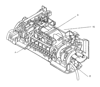
In the preferred embodiment of the instant invention, pump assembly
consists of a plurality of sub-assemblies as shown in Figure 1, which
perform various associated functions in concert with the pump sub-assembly
5 12.
THE PUMP SUB-ASSEM$LY
The pump sub-assembly, as seta in Figure 2, comprises a housing 14
to which various associated elements are affixed. Housing or chassis 14 is
Io preferably made of a molded plastic so as to speed assembly and fabrication
thereof. Chassis 14 further comprises an aft plate 16 formed integral with
chassis 14, wherein aft plate 16 has defined therein a plurality of apertures.
Motor shaft aperture 18 is substantially centrally located in aft plate
16 and is operative to allow pump motor shaft 20 to pass therethrough . Aft
is plate 16 further has defined therein pump motor mounting holes 22 which
are spaced radially outwardly from pump motor shaft aperture 18. These
holes serve to locate accurately pump motor 24 in combination with the
motor bearing boss with respect to the chassis 14. Abaft of the aft chassis
plate 16 are a plurality of mounting wings 26 which are operative to securely
2o fix the chassis to the downstream platen 500 located on the downstream side
of the chassis 14 and the upstream platen located on the upstream side of the
chassis I4; wherein upstream denotes the side of the assembly 10 which is
located closer to the fluid inlet thereto and downstream denotes that side of
the assembly 10 which is located closer to the fluid outlet therefrom.
2s As seen in Figs. 2 and 3, chassis 14 further defines a plurality of
apertures substantially transverse to the pump motor axis 32 which is defined
as being coaxial with pump motor shaft 20.
CA 02404845 2002-10-28
-13-
Set before wings 26 is an upstream fluid barrier tab 27A and a
downstream fluid barrier tab 27B which are cooperative with the slide clamp
actuator support and downstream platen aft plate 580 to provide a fluid
shield between the fluid source (IV tube or set) and the associated elxtrical
s apparatus located abaft of the combined fluid stop assembly composed of the
three clcments aforementioned.
These transverse ports or apertures serve to allow access to various
mechanisms interior to the chassis as shall be subsequently described and
also provide a single datum point to fix the relative locations of the various
io sub-assemblies which depend from the various parts associated with these
apertures. This style of manufacture provides an accurate and robust means
of fabricating the pump assembly IO whilst providing an economy of
measured points requiring adjustment to ensure correct operation of the
device. These apertures are reproduced on both the upstream sidewall 32
z5 and downstream sidewall 34 of the chassis I4.
The first such aperture set is the valve pivot shaft ports 36, 38 which
serve to support and locate the valve pivot shaft 410 relative to the chassis
14.
The second such aperture set supports the tubeloader camshaft 510
2o and is denoted as the tubeloader camshaft ports 40, 42.
The third such aperture serves to support and locate, relative to the
chassis 14, the tubeloader layshaft 512 and is denoted the tubeloader layshaft
apertures 44, 48.
The fourth such aperture set serves to allow access of the pump valve
25 cam actuators 422, to the interior of the chassis 14, and is denoted valve
actuator ports 46, 50.
The chassis defines a cavity 52 therein which serves to house the
pump drive sub-assembly as shown in Figure 2.
CA 02404845 2002-10-28
-14-
The pump motor 24 is the aftmost element of this sub-assembly.
Tfiis motor is preferably a variable speed d.c. motor having an internal speed
reduction gearbox 54 which in the prefennd embodiment provides a 64 to 1
reduction of motor speed.
s The output of the pump motor gearbox 54 is pump shaft 20. Pump
shaft 20, as aforedescribed, extends axially into cavity 52 via pump shaft
aperture 18.
Interior to cavity 52 and in circumferential engagement with pump
shaft 20 is drive collet 56. Drive collet 56 has a further mechanical
io engagement with pump shaft 20 via a combination of a plurality of collet
flats 58 which are impressed on shaft 20 so as to provide a polygonal surface
operative to engage grubscrews 60 which thread through collet 56 via
threaded grubscrew holes 62 which are situated radially and transversely to
shaft axis 32 though drive collet 56. Drive collet 56 further has defined
is therein a drive pin aperture 61 which is longitudinally parallel and
radially
outwardly from pump shaft axis 32 and is operative to support and drive
fixing pin 63 in concert with movement of collet 56 and motor shaft 20.
Surmounting drive collet 56 and coaxial therewith, is the pump index
wheel 64, as shown in Figure 4.
2o Index wheel 64 is operative, with associated sensors, to determine the
location of the pump elements. The index wheel has defined therein a first
radial slot 66 and a second radial slot 68, which are about the periphery of
index wheel 64. These two slots are located 180 degrees away from each
other.
25 The index wheel 64 is comprised of a whtel disc portion 70 and a
hub portion 72 wherein the hub portion 72 is radially interior to and
substantially forward of the wheel disc portion 70. The hub portion 72 of
the index wheel 64 is connected to the wheel disc 70 by a plurality of webs
CA 02404845 2002-10-28
-15-
74 extensive from the hub 72 to the disc 70. The hub portion further
comprehends a cylindrical longitudinally extensive portion 76 and a
transverse annular portion 80, wherein the cylindrical portion 76 extends
forward of disc plate 70 and the annular portion 80 extends radially inwardly
s from the cylindrical portion 76 to the motor shaft 20.
Annular portion 80 further defines a motor shaft port 82 which is
coextensive with the motor shaft 20 and a fixing pin port 84 located outward
from the motor shaft port 82 and parallel therewith. The motor shaft port 82
allows the motor shaft 20 to pass through the index wheel 64 while the
io fixing pin port 84 enforrxs co-rotadon of the motor shaft 20 and the index
wheel 64 when fixing pin 63 is inserted therethmugh.
Hub portion 72 has defined therein two access ports 86, 88 which
allow access to the collet grub screws 60. 1"hese hub access ports 86, 88 are
accessible from the exterior of the chassis 14 via set screw access port 90.
is Surmounting the index wheel 64 and forward of the annular portion
80 thereof, resides the pump drive cam 100 shown in Figs. 5 and 6. Pump
cam 100 consists of a front face area 102 and a rear face area 104.
The front face area 102 further comprises an exterior cam Iand 106
and an interior cam land 108. The exterior and interior cam lands 106, 108
2o are cooperatively formed so as to provide positive actuation of pump cam
follower 110. The shape and aspect of the two lands 106, 108 are non-linear
with respect to the variation of distance of various parts of the lands 106,
108 from the pump shaft axis 32.
The rotary to linear motion conversion, as realized by cam 100,
25 introduces non-linear error, as shown in Figure 7, in the volumetric output
of the pump with respect to time (as measured in shaft encoder counts). The
aspect of the interior Iand 108 and the exterior land 106 act cooperatively to
achieve a first order correction of this error so as to linearize the output
of
CA 02404845 2002-10-28
-16-
the pump with rGCpect to volume. This is achieved by an alteration of the
change in radial displacement of the cam lands 106, 108 with respect to the
motor shaft axis 32 as aforedescribed so as to minimize the effects of angular
error on the accuracy of the pump.
s Specifically, to a first approximation the cam executes an inverse sine
function as determined by the radial distance of the lands 106, 108 from the
shaft axis 32.
As can be seen in Figure 7, the characteristic volumetric output of a
tube between two v-grooves executing a relative motion is a non-linear
io function of displacement of the grooves. This shuttle 200 structure is
recited
in the Patent to Danby et al, U.S. Pat. No. 5,150,019 corresponding to
U.K. Pat. No. 2,225,065 as aforerecited.
As seen in Figure 5, the alteration of the cam profile, as herein
described, provides a markedly more linear output by increasing the shuttle
is speed during the middle of the stroke (between 30 degrees and 60 degrees of
cam angle) and decreasing the speed of the shuttle 200 at the beginning and
end of the stroke.
As seen in Figure 9, this variable linear velocity provides a
significantly more linearised volumetric output wherein output is essentially
20 linear between 30 degrees and 70 degrees of cam angle. The variation
between upward and downward strokes being due to use of simple radii
within the cam.
Referring now to Figure 5, which depicts cam lands 106, 108 in face
on aspect, shows the various cam positions clearly. As shown, there are two
25 primary pumping portions 110, 112 corresponding to downward and upward
movements of the shuttle 200. Also seen are dwell portions 114, 116 which
allow the inlet and outlet valves to be actuated as shall be subsequently
described.
CA 02404845 2002-10-28
-1~-
Further linearizadon of output is controlled electronically via a
position sensitive speed control which shall be subsequently described.
Referring now to Figure 6, the reverse side 118 of cam 100 is shown.
As can be seen, there are two concentric valve cam lands I20, I22. In this
s embodiment, the inner valve cam land I20 drives the upstream (inlet) valve
and the outer valve cam land 122 drives the downstream (outlet) valve. As
can be seen, at no time are the inlet and outlet valves simultaneously
operated, thereby positively preventing a free flow condition of medicament.
The duration and dwell of the valve cam lands 120, 122 are arranged to
1o provide for proper valve synchronization although the inner valve cam race
120 and the outer valve cam race 122 are at differing radii as measured from
the pump shaft axis 32.
The rear hub 118 of the drive cam 100 also defines a cam fixing in
port 124 which serves to lock the relative location of the drive cam 100 to
1s that of the drive collet s6, via fixing pin 63 and, therefore, to that of
motor
shaft 20.
Motor shaft 20 is capped by nosebearing 126 which is located
immediately afore cam 100. The motor shaft 20 passes through cam 100 via
cam motor shaft port 127 defined centrally in the cam 100. Surrounding
2o cam motor shaft port I27 is the forward cam annulus 128 which serves as a
lash adjustment for cam 100 float along motor shaft 20 between collet 56
and nosebearing 126.
In the preferred embodiment of the instant invention, nosebearing
126 is a roller type bearing. Nosebearing 126 fits into the nosebearing race
25 132 in the rear side of the shuttle platen 130.
Shuttle platen 130 is affixed to the forward chassis surface 53 by a
plurality of fasteners which connect shuttle platen I30 to forward chassis
surface 53 via a plurality of fastener ports 134 defined in the shuttle platen
CA 02404845 2002-10-28
-18-
130 and a second plurality of fastener parts 136 defined in the forward
surface 53 of chassis 14. The relative location of the shuttle platen 130 with
respect to the chassis 14 is defined by register pins 138 in the forward
chassis surface 53 for which corresponding shuttle platen register ports 140
are defined in the back surface of shuttle platen 130.
Shuttle platen 130 additionally has defined therethrough a shuttle
drive cam follower throughport 142 which is defined to allow the shuttle
actuating cam follower 144 access to the shuttle drive cam 100. The front
surface of the shuttle platen 146 defines a plurality of channels 148 in which
io the shuttle 200 resides. These shuttle platen channels 148 are of a low
friction finish so as to allow free movement of the shuttle 200 thereacross.
The front shuttle platen surface 146 further defines side rails 150, 152 which
are operative to limit torsional movement of the shuttle 200 as the shuttle
200 performs its motion.
i5 Throughport 142, as aforementioned, allows passage therethrough of
cam follower 144. Cam follower 144 is an annular roller bearing of such
dimension as to allow motion thereof between the pump drive cam lands
106, I08. The shuttle drive cam follower 144 rides on the shuttle drive pin
154 which resides in the shuttle drive pin recess 156 so as to be flush with
2o the front surface 201 of the shuttle 200. The drive pin 154 further
comprises
a head 158 which is operative to spread drive forces evenly to the shuttle Z00
and furthermore, provides an adequate peripheral area for effective press-fit
connection thereof to the shuttle 200.
The shaft portion 160 of the shuttle drive pin 154 extends through the
2s shuttle 200 via drive pin port 202 defined therein, and is sufficiently
extensive to pass through the shuttle platen 130 and engage shuttle drive cam
follower 144.
CA 02404845 2002-10-28
-19-
The shuttle platen 130 completes the datum or register point set based
on measuring locations throughout the pump 10 fmm the chassis 14 and
associated components.
The shuttle platen side rails 150, 152 have forward surfaces 162, 164
s upon which are located a plurality of datum surfaces 168, I70. These datum
pads 168, 170 are operative to fix the distance from shuttle 200 to that of
the
upper jaw 220 of the pump assembly. This distance, experiment has found,
must be maintained at 0.2 mm. This distance is critical due to the pump
geometry wherein, as shown in Figure 10, the initial deformation of the tube
1o section acted upon by the pump is dependent upon the lateral distance
between the moving shuttle indent 204 and the fixed, or non-moving, indent
206 so as to provide a deformation of the initially circular tube cross-
section
to an equiangular quadrilateral cross-section. This initial deformation bears
on the amount of closure of the pump tube lumen 6 as the pump cycles
1s through its stroke; as the stroke throw is fixed by the lift of the drive
cam
lands 106, 108. The amount of deformation of the pump tube lumen fixes
the volumetric output of the pump, per stmke or cycle thereof.
The lower portion of the side rails 150, 152 are laterally extensive
beyond the shuttle 200. The forward surfaces of the lower lateral extension
20 172, 174 have associated therewith a second set of datum pads 176, 178
which are operative to fix the distance of the lower fixed jaw 222 from the
shuttle 200. The function of these lower jaw datum pads 176, 178 are
similar to the function of the upper datum pads 168, 170 as aforedescribed.
Shuttle 200 further comprises, as shown in Figure 11, a rear side 207
25 of the shuttle 200. The rear shuttle side 207 further has defined therein a
plurality of slide rails 206. The slide rails 206 are operative to provide for
a
minimization of friction betwixt the shuttle 200 and the shuttle platen I30.
The slide rails 206 are in substantially full face engagement with the
CA 02404845 2002-10-28
-20-
channels 146A of the shuttle platen I30, and provide a fixation of both
longitudinal and lateral lash between the shuttle 200 and the shuttle platen
130.
The front surfaces 201 of the shuttle 200 defines a pump groove
s aperture 204. This aperture, or indent 204, is of a substantially v-shaped
cross-section and has a rounded interior corner Z I 1 so as to provide for a
conformation of the tube 5 and the groove aperture 204 when the tube 5 is
loaded therein.
The rear surface 207 of the shuttle 200 further has defined therein a
Io plurality of pockets 203 arranged in a substantially vertical array. These
pockets 203 are adapted to contain a plurality of magnets which are
cooperative with a magnetic sensor 322 to sense the linear position of the
shuttle 200.
15 SENSORS ASSOCIATED WITH THE PUMP SUB-ASSEMBLY
The pump sub-assembly, as previously described, has associated
therewith a plurality of sensors which are operative to provide information as
to the function and location of the various elements thereof.
The aftmost of the sensors is the drive motor shaft encoder 300. This
2o sensor comprises an encoder flag wheel 302 which is attached to the
armature shaft 303 of motor 24. The pump motor flag wheel 302 has, in the
preferred embodiment of the instant invention, twelve flags 304 extending
radially outwardly from the hub 306 thereof.
These flags 304 act in concert with two optical switches 308, 310 to
25 fix the location of the armature shaft 303 of the pump drive motor 24. The
switches 308, 310 further consist of a light emitting diode and a photocell as
shown in Figure 12. The arrangement of the optical switches 308, 310
allows for a first switch 308 to sense the edge 311E of flag 304, and the
CA 02404845 2002-10-28
-21 -
second switch 310 to sense the middle 311M of a subsequent flag 304. This
arrangement allows for greater resolution of motor shaft position and
direction as read by the encoder 300.
In this presently preferred embodiment, the resolution of encoder 300
is 1/3072 of a rotation of motor shaft 20. The encoder assembly 300 resides
in a pump motor encoder support collar 312 which is a sliding fit over motor
housing 24 and is affixed thereto by pinch clamp 313.
The motor encoder 300 senses armature shaft 303 rotation dir~xtly.
However, as there are mechanisms resident between the armature shaft 303
to and the shuttle 200, further sensors are desired.
Moving forward along motor shaft axis 32, one returns to index
wheel 64. As aforementioned, index wheel 64 has a plurality of
circumferentially coextensive radially disposed slots 66, 68. Associated with
these slots is an index wheel optical sensor 3I4. This sensor comprises a
is light emitting diode 315 and an optical sensor or switch 316.
The index wheel sensor 314 is cooperative with the index wheel 64
and the slots 66, 68 therein to provide positional information of the
rotational location of the pump motor shaft 20.
In operation, the index wheel sensor 314 acts in concxrt with the
2o pump encoder 300 to provide this positional information as well as
directional information of the motor shaft 20. The index wheel sensor times
the passage of each of the slots 66, 68 past the index wheel switch 314. The
two slots 66, 68 are of differing widths so as to provide information as to
whether the shuttle 200 is beginning the upstroke thereof or the downstroke
25 thereof, where a first width indexes the upstroke and a second width
indexes
the downstroke.
Associated with the shuttle 200 itself is a linear gross position sensor
320. This sensor comprises a linear position Hall effect sensor 322 and a
CA 02404845 2002-10-28
plurality of magnets 324, 326. Shuttle position sensor magnets 324, 326
present opposite poles to the shuttle Hall switch 322, so as to provide a
field
gradient operative to provide an indicium of the linear position of the
shuttle
200.
The combination of the encoder 300 and the other associated sensors
aforementioned, provide inputs to a control mechanism, which may operate
more than one pump so as to accurately control the speed of variable speed
motor 24, the primary feature provided by such spetd control is a temporal
variability of the output of the pump 10. Additionally, such speed control
allows for an electronically controlled Iinearization of the pump output per
individual stroke as well as improving the time integrated output of the pump
10. In the preferred embodiment the per stroke linearization of output is
realized in combination with the drive cam 100 as aforementioned. The time
integrated output of the pump is made more accurate by the pump spetd
~s being markedly increased at such points as would provide for a
discontinuity
in the output profile as measured with respect to time so as to minimize the
effects of such discontinuities in output.
As a manufacturing convenience, both the shuttle linear position
sensor 320 and the index wheel sensor 314 are electrically connected to the
2o associated signal processing electronics by a shared printed circuit strip
denoted as the pump sensor circuit strip .
T~ Vnt.vE SUB-~ss~eLY
The valve sub-assembly is shown, removed from the associated pump
25 sub-assembly, in Figures 13 and 14. The valve sub-assembly consists of a
valve pivot shaft 410 which is carried by chassis 14 by being supported
thereby in pivot Shaft ports 36, 38. Valves 412, 414 pivot about this shaft
CA 02404845 2002-10-28
-23-
410 and are supported thereon by valve pivot bearings 416, 418 which are
clearance fit onto pivot shaft 410 and into valves 412, 414.
The two valves 412, 414 are denoted individually as the upstream
valve 412 and the downstream valve 414 . The upstream valve 412
s comprises a pivot bearing aperture 420 adapted to accept thereinto the
upstream valve pivot bearing 416 and thereby pivot about valve pivot shaft
410. The upstream valve 412 further comprises an upstream valveshaft
aperture 422 which is located axially parallel to the pivot shaft 410 and
substantially vertically displaced therefrom. The upstream valveshaft
io aperture 422 is adapted to slidingly roceive the upstream valveshaft 424
therein. The upstream valveshaft 424 extends laterally from the upstream
valve 412 and is disposed to enter into the chassis 14 via upstream valveshaft
aperture 48. The upstream valve actuator shaft 424 is substantially
cylindrical and has defined therein an outer cam race cutout 426. The outer
is cam race cutout 426 is operative to allow the upstream valve actuator 424
to
clear the outer or downstream valve race 122 defined on cam 100. The
upstream valve actuator 424 terminates in a cam follower nub 428, which is
adapted to support the upstream valve roller cam follower 430. The
upstream cam follower 430 is, in the preferred embodiment, a roller bearing
2o so as to provide rolling contact between the valve cam land 120 and the
upstream valve actuator 424.
Returning to valve 412 or 414, the valve further comprises a valve
blade 432, as shown in Figure 15B, which is of a substantially v-shaped
cross-section wherein the first side of the valve blade 434 and the second
2s side of the valve blade 436 subtend an angle of approximately 90 degrees
therebetween and also define a 0.5 millimeter rounded vertex 438. The
combination of the included angle and the rounded vertex 438 provide for an
optimal arrangement between the conflicting necessities of ensuring that the
CA 02404845 2002-10-28
-24-
tube 5 is sealed during the appropriate part of the pump cycle while
simultaneously ensuring that the tube will reform into an accurate
approximation of its initial shape when the valve blade 432 is lifted from the
tube 5.
The rounded vertex 438 of the valve blade 434 defines a Ø5 mm
curvature. This curvature, in combination with the 0.7 mm distance
between the valve blade 434 and the valve anvil 570, to be discussed
subsequently, provide for an optimization of the two necessities of ensuring
sealing while providing for elastic recovery of the tube during the
io appropriate part of the pump cycle.
Additionally, the tube 5, due to its deformation by the shuttle Z00 in
combination with the upper and lower jaws 220, 222, comprehends a partial
vacuum within that portion of the tube lumen 6 located adjacent to shuttle
200, and the opening of the inlet valve 412 with the positioning of the
is shuttle 200 providing conditions conducive to assist hydrodynamically the
elastic recovery of the tube section below the inlet valve 412.
The upstream valve body 412 further comprises a valve lifting tang
440 which is cooperative with a valve loading cam to raise the valve during
the tube loading operation. The valve body 412 comprehends a valve spring
2o seat tang 442 which extends upwardly from the distal end 444 of the valve
blade arm 435. The valve spring tang 442 defines a valve spring retainer
port 446 which is operative to provide support for the distal end 448 of the
valve spring retainer 450. The valve spring retainer 450, in combination
with valve spring tang 442, serves to completely capture the valve spring
25 452 therebetween. The valve spring retainer 450 comprises a substantially
c-shaped base 454 which is operative to slidingly fit about the tubeloader
layshaft 512, to be described subsequently. The valve spring retainer base
454 is designed to permit oscillatory motion of the retainer 450 about the
CA 02404845 2002-10-28
_ 25
aforementioned tubeloader layshaft so as to accommodate the motion of the
valve 412, 414.
The downstream valve 414 is resident on the valve pivot shaft 410
adjacent to the shuttle 200. The downstream valve 414 is essentially a
mirror image of the upstream valve 412 about a plane transverse to the pivot
shaft 410 and displays all of the associated elements of the upstream valve
412 in a reversed orientation as seen in Figure 14. The downstream valve
actuator arm 456 is shortened to align the downstream valve cam follower
458 with the outer valve cam land 122.
Io The action of the two valves 412, 414 is such that at no time during
the pump cycle are both valves open at the same time. Furthermore, as both
the valves 412, 414 and the shuttle 200 are driven by a single motor 24 and
off of a single drive cam body 100, exact synchronization of the valves 412,
414 and the pump shuttle 200 is positively achieved by wholly mechanical
~s means.
SENSORS ASSOCL4TED WITH THE VALVE SUB-ASSEMBLY
Associated with each of the valves 412, 414 is a valve motion sensor
328, 330. Each of these valve motion sensors 328, 330 is actuated by a
2o magnet 332, 334 which is inserted into a valve sensor magnet port 332A,
334A in the outboard end 444 of the valve blade tang 435. Located
therebelow, in the associated valve anvil and outwardly located therefrom is
the valve motion sensor Hall switch 328, 330 which, with associated
software, linked to the output of the valve sensor switches 328, 330 to that
2s of the drive motor encoder 300, serves to stop the pump 10 and activate an
alarm if a valve 412, 414 is not operating correctly. This is essentially
accomplished by comparing the expected output of the appropriate valve
CA 02404845 2002-10-28
sensor 328, 330 with the expected signal therefrom at a specific motor 24
and drive cam Iocation.
Residing outwardly from each valve 412, 414 and separated
therefrom on valve pivot shaft 410 by tube present arm spacers 460 is the
s tube present sensor arm 340. The upstream tube present sensor, in
conjunction with the downstream tube present sensor, serves to determine
the actual physical presence or absence of the IV tube in the pump 10. Each
of the tube present sensors 332, 334 comprises an annular bearing or tube
sensor pivot 336 which surrounds and rides on the valve pivot shaft 410.
The tube sensor arm web 338 extends outwardly from the tube sensor pivot
336 and serves to support the tube sensing blade 340 which extends
forwardly from the sensor arm web 338 and the tube sensor flag 342 which
extends substantially rearwardly from the sensor arm web 338. The sensor
blade 340 comprises a downward extension thereof so, when installed, the
is sensor blade tip 344 resides on the appropriate valve anvil. The insertion
of
a tube 5 between the blade tip 344 and the valve anvil will, therefore, serve
to raise the blade 340 away from the anvil 570 and cause the sensor arm to
pivot about the valve pivot shaft 410. This serves to Iower the rearwardly
extending valve sensor flag 342 thereby interrupting the tube present sensor
20 optical switch 346 by the flag 342 moving into the interstice 348 of the
tube
present sensor optical switch 346 and interrupting the light beam extending
thereacross, as shown in Figure 17. A return spring 350 serves to bias the
tube sensor arm to a position wherein, should the tube 5 not be present, the
tube sensor blade tip 344 rests on the associated valve anvil.
2s
THE TUBELOADER SUB-ASSEM$LY
As shown in Figures 18 and 19, the tubeloader sub-assembly utilizes
two shafts associated with chassis 14. These two shafts are the tubeloader
CA 02404845 2002-10-28
- 27 -
camshaft 510 and the tubeloader layshaft 512. These two shafts 510, 512, in
conjunction with the valve pivot shaft 410, provide the primary datum points
for the relative locations of the various assemblies and associated elements
thereof, throughout the pump. The locations of these three shafts is shown
in Figure 3. By referencing all points in the pump to these shafts, and
thereby to the chassis 14, the pump structure can be indezed without the
necessity of a wide variety of precision machined parts, whilst maintaining
the requisite accuracy of the completed assembly.
The tubeloader layshaft 512 provides an axis about which all parts
io which are driven by camshaft 510 rotate save the valves and slide clamp.
Moving upstream along layshaft 512, the most outboard of the elements
associated therewith are the downstream tubeloader pawls 514. The
downstream tubeloader pawls each consist of an annular body 516 which is
adapted to ride on the tubeloader layshaft S I2 and is fixed thereto by the
is associated helical pin 518 which eztends through the pawl annulus 516 and
the layshaft 512 and into the opposed area of the annulus, thereby positively
fixing the associated pawl 514 to the layshaft S I2. Extending forward of
the pawl annulus or collect 516 is the pawl arm 518. The pawl arm has a
substantially linear section 520 and an arctuate section 522 extending
20 outwardly and downward from the pawl collet 516.
The shape of the arctuate section 522 of the pawl 514 is such that
when the pawl 514 is fully lowered, the tube 5 is firmly wodged against the
downstream platen 500, thereby encircling the tube 5 between the pawl S I4
and platen 500.
25 In greater detail, the interior angled surface 526 of the pawl tip 524
intersects the tube 5 at an approximately 45 degree angle with respect to
horizontal and is thereby operative to urge the tube 5 downwardly and
inwardly against the tube detent 501 in the downstream platen 500.
CA 02404845 2002-10-28
-28-
The pawl tip 524 encompasses a plurality of.areas. The interior side
of the tip defines a horizontal tube engaging surface 525, an angled tubc
engaging surface 526, a vertical tube capture surface 528, a horizontal tube
misload activating surface 530 and an externally facing tube rejection surface
s 532 on the exterior side theroof; and the aforementioned surfaces are
disposed on the periphery of the pawl tip. These surfaces operate in concert
with the downstream platen 500.
The design comprehended by tubeloader pawl tip 524 is repeated on
the lower edge of the upper pump jaw 220 and serves an identical function
io as shall be described herein.
When an operator is loading a tube into pump 10 and actuates the
tubeloading cycle by means of an appropriate actuator, or a contml button
or switch, the tubeloader pawl tips 524 are lowered over tubeway 8 which,
in combination with the lowering of the upper jaw 220, serves to completely
~s close off the longitudinal slot or opening on the outboard side of tubeway
8.
Should a tube be partially inserted into the pump 10, yet remain wholly
outside the tubeway 8, the tube reject surface 532 will operate in
combination with nesting slots 582, which are also resident on lower jaw
222, to expel the tube 5 from the pump. In the event of a tube 5 being
20 loaded partially within the tubeway and partially exterior thereto, the
misioad activating surface 530 will serve to pinch the tube 5 between the
misload activating surface 530 and the associated section of either the
downstream platen 500, the upstream platen 800, or the lower jaw 220 and
thereby actuate a misload detection as described herein. Another possibility
25 contemplated in the design of the pawl tip 524 is wherein the tube 5 is
inserted into the wbeway 8 yet has not been fully drawn into contact with the
tubestops 576. In this event, the tube capture surface 528 will serve to draw
the tube 5 rearwardly and into contact with the tubestops 576 and thereby
CA 02404845 2002-10-28
-29-
execute a correct loading of the tube. The combination of the tube reject
surface 532, the misload activating surface 530 and the tube capture surface
528 provides for a sharp discontinuity between the various possibilities for
loading scenarios aforementioned.
s The vertical tube capture surface 528 additionally works in
combination with the angled tube engaging surface 526 and the horizontal
tube engaging surface 525 to hold the tube 5 securely against the tube stops
576 and to pmvide for a deformation of the tube 5 by co-action of the angled
surface 526, the horizontal surface 525 and the tube stop 576 to lock the tube
io securely into the tubeway 8 when the longitudinal tubeway aperture is
closed
as well as to provide substantially full face engagement of the tube 5 with
the
associated sensors
The downstream platen 500, or the corresponding upstream platen
800, are preferably constructed of a molded plastic such as glass filled
is polyphenylsulfide. The downstream platen 500 serves a variety of functions.
The tubeloader bearing cup 502 provides for a mounting area for the
tubeloader powertrain.
Gearbox sidewalls 503A serve to house the tubeloader gearset 560
which comprises two helical gears 562, 564 in a perpendicular arrangement
2o so as to transfer rotation from a fore and aft mounted tubeloader motor 550
to the transverse tubeloader camshaft 510. The downstream platen 500
gearbox housing further comprehends a camshaft bushing race 566 which
serves to support the downstream camshaft bushing 568 in which the
camshaft moves. The forward section of the downstream platen 500
25 comprises the downstream valve anvil 570 as well as the temperature sensors
ports 572 and the lower air sensor transducer housing 574. Abaft of these
areas are a plurality of tube stops 576 which serve to support the tube 5
CA 02404845 2002-10-28
-30-
rearvvardly so as to provide controlled conformation of the tube S when in
the loaded condition.
Abaft of the tube supports 576, the downstream platen 500 further
provides for the downstream sensor pivot slot 578 which, in concert with
associated apparatus, serves to correctly locate the downstream sensor array
as shall be described. The rear barrier wall 580, cooperative with chassis
14, serves as a fluid barrier between tube 5 and the electrical components
behind the rear barrier wall 580. The rear barrier wall 580 is affixed to the
chassis 14 by fasteners and additionally serves a fastening point for the
1o downstream tube present sensor switch 346.
Returning to the foreward edge of the downstream platen 500, a
plurality of tubeloader pawl nesting slots 582 are seen. These pawl slots
582, in combination with the tubeloader pawls 514 and the chamfered
forward edge 584 of the downstream platen 500, serve to promote a correct
i5 loading of the tube 5 into the pump 10 by allowing the pawls 514 to lift
and
push the tube rearwardly against the tube stops 576. Outward of the
outermost of the pawl nesting slots 582, a tube retaining detent 584 serves to
retain the tube 5 in a position adapted to be captured by the pawls 514
during initial placement of the tube 5 within the tubeway 8 defined by the
20 raised pawls 514 and the downstream platen 500 when the tubeloading
assembly is in a state allowing the tube 5 to be loaded.
As aforedescribed, the tubeloader motor 550 drives, by means of a
plurality of gears, the tubeloader camshaft 510. The tubeloader motor 550 is
a d.c. motor. The tubeloader motor 550 further comprises a speed reduction
25 gearset 534 operative to provide sufficient torque to rotate camshaft 510
against the drag placed thereon by the components in contact therewith and
resident on layshaft 512.
CA 02404845 2002-10-28
-31-
The tubeloader motor shaft 536 eztends forwardly from the
tubeloader motor 550 and passes through the tubeloader motor mount 538 by
way of a central aperture 540 therein.
The tubeloader motor shaft 536 has a flat 542 defined therein which
is operative to provide a seat for the tubeloader drive gear setscrew 544
which is inserted thmugh a threaded setscrew aperture 546 in the tubeloader
drive gear 562 and thereby fiz the rotation of the tubeloader drive gear 562
to that of the tubeloader motor shaft 536.
The tubeloader drive gear 536 is a helical cut gear wherein the teeth
to thereof are about the circumferential periphery thereof. These teeth engage
corresponding teeth on the face of the tubeloader camshaft gear 564, thereby
allowing perpendicular actuation of the transversely mounted camshaft 510
by the longitudinally mounttd tubeloader motor 550.
The tubeloader camshaft gear 564 is releasably engaged with the
is camshaft 510 by means of a slideable engagement pin 588.
The camshaft clutch pin 588 is cooperative with a clutch slot 590 on
the rear or inboard facing face of the camshaft gear 564. The clutchpin 588
resides transversely to the camshaft 510 in a longitudinal clutchpin slot 592
defined thmugh the camshaft 510. A longitudinal actuator pin 594 coaxiaily
2o emplaced within the camshaft 510 and in endwise contact with the clutchpin
588 serves to selectively insert and allow the withdrawal of the clutch pin
588 from engagement with the clutch slot 590 on camshaft gear 564. A
biasing spring 596 is located within the camshaft 510 and in opposition to
the longitudinal actuator pin 594. The outboard end 598 of the actuator pin
2s 594 is munded to allow sliding contact therewith by the associated
component.
Handwheel 600 provides a housing for a pivoting clutch tab 602
which comprises on its inboard facing surface a clutch cam 604 which is in
CA 02404845 2002-10-28
-32-
sliding engagement with the outboard end 598 of actuator pin 594. The
clutch tab 602 is interior to handwheel 600 and is hingod thexeto by a clutch
tab pivot pin 606. In operation, actuation of the clutch tab 602 by tilting
same about clutch tab pivot pin 606 will cause the clutch cam 604 to impinge
on and depress the outboard end 598 of the actuator pin 594 causing the
actuator pin 594 to move inwardly against clutch biasing spring 596 and
moving clutch pin 588 inwardly and out of contact with the clutch slot 590
in camshaft gear 564, thereby allowing the camshaft 510 to be freely rotated
manually by means of handwheel 600 without rotating the camshaft gear
564.
The camshaft 510 is one of the three primary datum shafts resident in
the pump 10. The camshaft supports two compound cams denoted as the
downstream cam 610 and the upstream cam 620.
The downstream and upstream cams 610, 620 comprise, moving
~5 outwardly from chassis, a camshaft deadstop 612, 622, a tubeloaded pawl
cam 614, 624 which is itself a compound cam, and valve loading cam 618,
628.
The camshaft deadstops 612, 622 work in cooperation with the
chassis rotator stops 28, 30 to provide a positive stop for camshaft rotation.
2o Associated electronics sense the stall condition of the tubeloader motor
550
and interrupt power thereto when the camshaft deadstops 6I2, 622 are in
contact with the chassis rotator stops 28, 30 during an initial indexing cycle
of the tubeloader assembly, thereafter the tubeloader 550 ~in combination
with the tubeloader encoder 702, 704, 705 will back-count from the rotator
25 stops 28, 30 and under control of associated software interrupt power to
the
tubeloader motor 550 prior to the deadstops 612, 622 making contact with
the chassis rotator stops 28, 30.
CA 02404845 2002-10-28
-33-
Moving outwardly from the camshaft deadstops 612, 622, the
tubeloader pawl cams 614, 624 save to actuate the tubeloader pawls 514.
Additionally, each of the tubeloader pawl cams 614, 624 has a locking
surface 616, 626 which serves to activate a second, rigidly affixed lifting
s follower associated with the tubeloader layshaft 512 so as to provide a
positive fixation of the associated elements when the layshaft S I2 reaches
the
end of its travel.
Outward of the pawl cams 614, 624 are the valve loading cams 618,
628. These cams serve to lift the valves 412, 414 out of the tubeway 8
io during the loading operation. The valve loading cams accomplish this lift
in
cooperation with the valve loading tangs 440 as aforedescribed.
Outermost on the camshaft 510 reside the sensor arm cams 630, 632.
The downstream sensor arm cam 630 comprises a single surface and is
operative to raise or lower the downstream sensor arm.
is The upstream sensor arm cam 632, however, is a compound earn
having a sensor arm actuating surface 634 and, located outwardly therefrom
and integral therewith, the slide clamp loader crank 650.
All of the cams associated with camshaft 510 are fastened thereto by
helical pins driven transversely through the hubs of the various cams and
2o through the camshaft 510.
The tubeloader layshaft 512 supports all of the loading members
associated with placing the tube 5 in the tubeway 8. Additionally, the
layshaft serves to pivotally support other elements which arc driven at
differing rates than the tubeloader pawls 514. Innermost along layshaft 512,
25 wherein innermost defines that area closer to chassis 14, are the upper jaw
pawls 652, 654.
The upper jaw pawls are biased in an upward position by means of
helical pre-Load springs 656 which are wound about layshaft S I2 and are
CA 02404845 2002-10-28
-34-
hooked to and have one end hooked to the torsion spring stops 45 and 47,
associated with the tubeloader Iayshaft apertures 44, 46. The other end of
the preload spring 656 being hooked onto the respective upper jaw carrier
652, 654. Each of the upper jaw carriers 652, 654 further comprises a
s forwardly extending arm portion 658 which has a downwardly aimed
terminus 660. Forwardly extending arm portion 658 is adapted, in
combination with upper jaw tie rod 662, to support the upper pump jaw 220.
The downwardly extending termini 60 of the upper jaw carrier 652,
654 further define a distinctive tubeloading tip shape, as mentioned in the
~o description of the tubeloader pawls 514.
Located rearward of the forwardly extending arm portion 658, a
spring slot 664 is formed in the upper jaw carrier 652, 654 and is operative
to retain the associated torsion springs 656 therein. The upper jaw carrier
652, 654 have further defined a bifurcated central portion 667 which is
is adapted to retain the upper jaw carrier locking tangs 668 in the interstice
of
the bifurcated central portion 667 of the associated upper jaw canier 652,
654.
Extending rearwardly of the central area 667, an upper jaw carrier
cam follower arm 670 has defined therein an upper jaw cam follower port
2o 672 which is adapted to receive the upper jaw carrier arm cam followers
674. The upper jaw cam followers 674 are slidingly retained in the upper
jaw cam follower ports 672 and are biased against tubeloader pawl cam 614
624 by preload-spring 675. The purpose behind this being that should a tube
be misloaded beneath the upper jaw 220 or pawls 514, a sensor associated
2s with the position of the upper jaw 220 and in combination with a tubeloader
encoder 702, 704, 705, associated with the tubeloader motor armature shaft
701, will detect that the upper jaw 220 and Iayshaft 514 have ceased their
motion while the tubeloader motor continues to rotate as the clearance
CA 02404845 2002-10-28
-35-
between the upper jaw carrier cam follower arm 670 and the radially
extensive seat 676 of the upper jaw cam follower 674 is closed. An
electronic detection circuit will record this differential motion and cause
the
tubeloader motor 550 to reverse its rotation, opening the upper jaw 220 and
s tubeloader pawls 514 thereby expelling the tube 5.
To assure a final fixed registration of the upper jaw 220 and the other
assemblies driven by layshaft 514, the locking follower 668 rides up on the
locking surfaces 616, 626 of the tubeloader pawl cam or Iayshaft drive cam
614, 624, and is adjustably fixed relative to the upper jaw carrier arm 652,
654 by means of adjustment screws 680. The upper jaw carriers are fixed to
layshaft 512 by means of spiral pins so as to actuate a co-rotation thereof.
As seen in Figure 16, moving outwardly from the upper jaw carrier
arms are the valve spring retainers 450. Outward of the valve spring
retainers 450 resides the innermost of the tubeloader pawls 514 as
i5 aforedescribed.
Associated with, and pivotal about layshaft 512, are the upstream and
downstream sensor carrier arms 690. As it is necessary for the tube 5 to be
completely loaded in the tubeway 8 before the application of the associated
sensors, the sensor carrier arm 690 is actuated by a separate and delayed cam
2o with respect to action of the rest of the components affixed to layshaft
512.
Associated with each of the sensor carrying arms 690 is a downwardly
extending sensor arm cam follower 692 having a downward biased spring
694 associated therewith. Affixed to a central portion of the sensor carrying
arm 690 and in substantially opposing contact with the sensor arm cam 630,
2s 632 is the sensor arm opening spring 696 which, in the preferred
embodiment is a leaf spring. This arrangement allows for both the opening
of and the closure of the sensor array associated with the upstream or
downstream sensor carrier arm 690 by a single cam respectively.
CA 02404845 2002-10-28
-36-
As can be seen in Figure 16, the sensor arm 690 further comprises a
forward forcipate end 698 which is operative in combination with a sensor
handle pin 799 inserted thereacross, to support the associated sensor sub-
assembly.
s
SENSORS ASSOCIATED WITH THE TUHELOADER SUB-ASSEMBLY
As recited previously, there are a plurality of sensors associated with
the sensor arm 690 of the tubeloader sub-assembly. The most downstream
of these sensors is the ultrasonic air detection apparatus or transducer 728
as
io shown in Figure 22. The ultrasonic transducer 728 acts in concert with a
second transducer element located in the downstream platen 500, as
aforedescribed. The ultrasonic transducer 728 is housed in a compoundly
pivotal housing 720. This sensor housing 720 comprises a vertically split
housing body including a transducer cavity 724. The housing 720 further
Is comprises a substantially horizontally axially extensive suspension slot
722
which, itself, comprehends an oval joining ring 725, which is defined by a
substantially oval and longitudinally extensive sensor arm pin retainer 723.
The suspension slot 722 serves to capture the sensor handle pin 799, while
allowing the sensor assembly 720 to move in fore and aft relation thereto.
2o The sensor assembly 720 is further restrained by the vertically disposed
sensor arm pivot slot 578 in combination with sensar housing lift pin 721,
which is retained in lift pin ports 726 and 746 allowing vertical axial motion
thereof, to allow the sensor 720 to roll over or tilt against the top of tube
5
when the sensor arm cam 630 actuates the substantially downward motion of
2s the forward forcipate end of the sensor arm 690. This ability to roll over,
or
conversely execute a rocking motion with respect to the tube 5, allows the
sensor housing 720 to come into a substantially vertical compressive contact
with the tube 5. This allows the tube to be extended or stretched equally
CA 02404845 2002-10-28
-37-
acmss the face of the associated sensor, thereby eliminating either a
volumetric or stress gradient in the tube 5 beneath the associated sensor so
as
to improve the accuracy of response of the sensor associated with, or
connected to, housing 720. Essentially all of the sensors associated with, or
s actuated by, sensor arm 690 execute the above described motion so as to
achieve the above described result.
The next sensor located inboardly of the ultrasonic air detection
transducer 720 is the downstream pressure sensor which resides in housing
?34. The sensor itself comprises a fairly standard, full bridge array on a
io deflection beam 740. The deflection beam 740 is actuated by a sensing foot
730 which includes a substantially hemispherical tip 738. The hemispherical
tip 738 is surrounded by a conical extension of the housing 734. The
deflectability of the deflection beam ?40 is controlled by seat pin 742 and
stiffener 744 in conjunction with sensor foot fastener 743. The
is hemispherical foot tip 738, in combination with a conical circumferential
enclosure thereof has, to achieve maximum accuracy, the requirement that
the combination of the foot tip 738 and the conical enclosure be emplaced on
the tube 5 in an essentially normal orientation thereto which is achieved by
use of a compound rocker arrangement, as previously described, associated
2o with the transducer housing 720 as shown Figure 21. In this sensor, being
contiguous with the ultrasonic detector 720, the compound rocking motion
thereof is actuated by the lift pin 721 and oval rocker slot 722 of the
transducer housing 720.
The corresponding upstream pressure sensor resident in housing 750,
2s 760 provides an essentially similar layout save that the rocker assembly is
unitary with the housing halves 750, 760 and the racker slot associated
herewith is denoted as upstream slot 758 defined in the upstream rocker
handle 756 which includes oval inserts 754 and further comprises a separate
CA 02404845 2002-10-28
-38-
lift pin 752 riding in an associated vertical slot 810 in the upstream platen
800. Also associated with the tubeloader assembly is the tubeloader motor
encoder as aforementioned. The encoder comprises an encoder flag wheel
702 which, in the preferred embodiment, comprehends a tubeloader encoder
flag wheel hub 702A and a plurality of flags 702F, resident therebehind is
the tubeloader encoder support collar 703 which serves to support the
tubeloader encoder optical switches 704, 705 and is affixed to motor 550 via
pinch clamp 706 and further supports the optical switch printed circuit board
707.
to The downstream platen S00 also serves to support a plurality of
temperature sensors which consist of thermistors 754T and 755T which are
gasketed to the downstream platen 500 by means of gaskets 760T and are
supported from below by the thermistor support 762T.
THE SLmE CLAMP LOADER SUB-ASSEMBLY
The slide clamp loader sub-assembly and its related sensors are
generally associated with the upstream platen 800. The upstream platen 800
comprises a rearward facing fluid barrier wall 801 which is connected by
fasteners to chassis 14. The fluid harrier wall 801 serves with the rear wall
of the chassis and the rear wall of the downstream platen 500 to effectively
seal the electronic assemblies from fluid ingress. Mirroring the downstream
platen 500, the upstream platen 800 further has defined thereon a tube sweep
chamfer 812. With the substantially identical chamfer resident on the shuttle
facing interior side of the downstream platen 500, the upstream tube sweep
chamfer 812 accounts for forward shift of the tube therefor. The forward
facing edge of the upstream platen 800 future defines a plurality of
tubeloader pawl nesting slots 803 which are identical functioning to the
tubeloader pawl nesting slots 582. Furthermore, the upstream platen further
CA 02404845 2002-10-28
-39-
has defined therein a similar forward facing chamfer as the downstream
platen chamfer 584.
The upstream platen further has defined thereon the upstream valve
anvil 805 and a plurality of tube stops 809 of similar function to the tube
s stops 576 associated with the downstream platen 500. The upstream platen
further receives support from the upstream end of the valve pivot shaft 410
residing in carrier 807. The upstream-most end of the upstream platen 800
further has defined on the exterior peripheral edge thereof a upstream tube
retaining detent 842 which is identical in function and cooperative with the
io corresponding downstream tube retaining detent 584. The base of the
upstream platen 800 further has defined thereon a slide clamp loading groove
856. This groove, in combination with the upper slide clamp channel 824
resident in slide clamp carrier 814, serves to capture the slide clamp 895
through which passes tube 5. Additionally, present in the slide clamp
~s channel 824 are a plurality of slide clamp locating pins 824A, 824B which
serve to provide, in combination with an asymmetric slide clamp 895, a
preferred orientation of the slide clamp 895 and thereby as the slide clamp
895 is already resident on the tube 5, a preferred loading direction of the
tube 5 into the pump 10.
2o The slide clamp loader assembly is driven by camshaft 510 and is
actuated by the slide clamp loading crank 650. The slide clamp loading
crank 650 has inserted therein a slide clamp loading crank pin 804 upon
which rides a slide clamp actuator bushing 802. The rotation of this crank is
converted into a substantially linear motion by cooperative movement of the
2s slide clamp actuator bushing 802 and the slide clamp traveler 815 by means
of motion of the slide clamp actuator bushing 802 and the slide clamp
traveler bushing race 813. The slide clamp traveler 815 , in cooperation with
the slide clamp clam pin 826, provides substantially fore and aft motion of
CA 02404845 2002-10-28
the slide clamp clams 820, 830, which are operative to grasp and releasably
retain the slide clamp 895. The slide clamp clams 820, 830 are in a
substantially scissorlike arrangement with respect to each other and reside in
the slide clamp clam shell 832, which is operative to allow fore and aft
motion of the slide clamp clams 820, 830 therein. The tubeloader pawls
further serve to raise the slide clamp shield 811. This ensures that the slide
clamp 895 will not be accidentally removed from the pump 10 as the
position of the slide clamp traveler 815 provides that shield or visor 811
will
be in a lowered position at such time as the pump 10 is in operation, thereby
io precluding removal of the slide clamp from the slide clamp groove 856.
As aforementioned, slide clamp 895 is adapted to be gripped by the
slide clamp clams 820, 830. This is achieved by a cooperation between the
slide clamp 895, having detents or grippable elements impressed therein, and
the slide clamp loader clam tips 820, 822 which are essentially barblike so as
~s to ensure retention of the slide clamp 895 when the clams are engaged.
In operation the slide clamp loader functions in concert with the
tubeloader assembly to ensure correct loading of the tube 5 and the
associated slide clamp 895. After the tubeloader pawls 514 close about the
tube 5, the slide clamp loading assembly, specifically the slide clamp clams
20 820, 830, close onto the slide clamp resident about the tube 5 and within
the
slide clamp groove 856. As the pawls 514 close, and the upper jaw 220
lowers into its operating position, and subsequent to the valves 412, 414
lowering to close off the tube 5, the clams 820, 830 draw the slide clamp
895 into the slide clamp groove 856, thereby opening the slide clamp as it
2s slides past tube 5 which is being retained by the upstream tube stops 844.
The cam arrangement between the valve loading cam races 120, 122
and the tube loader cams assures that the slide clamp will be closed by a
reverse of the aforerecited motion of the slide clamp 895 with respect to the
CA 02404845 2002-10-28
-41 -
tube 5 prior to the tube being in a condition allowing removal thereof from
the tubeway 8.
SENSORS ASSOCIATED WITH THE SL)DE CLAMP LOADER
The slide clamp loader has two primary sensors associated therewith.
The first of these sensors is resident in the upstream platen 800 about the
slide clamp groove 856. This sensor is denoted the slide clamp positioning
sensor. The slide clamp positioning sensor is located on sensor base 880.
Resident on sensor base 880 are two light emitting diodes 872 and 876 which
to are positioned in a fore and aft arrangement on a first side of the slide
clamp
groove 856. Diametrically opposed to the light emitting diodes 872, 876
across the slide clamp groove 856, are a corresponding pair of photocells
870, 874. The photocells 870, 874 are also arranged fore and aft to align
with the diodes 872, 876. The diodes 872, 876 emit light into a first or
is transmitting pair of light pipes 864, 868 which extend upwardly above the
upstream platen 800 on one side of the slide clamp groove 856. The light
pipes 868, 864 terminate in 45 degree internal reflecting surfaces 863 which
serve to bend the output of the diodes 872, 876 into horizontal beams
transverse to the slide clamp groove 856 at a height suitable for intersection
20 of the beams with a slide clamp 895 present in the groove 856. A
corresponding set of receiving light pipes 860, 862 across from the
transmitting Iight pipes 864, 868 serve to receive the Iight beam emitted by
the diodes 872, 876 and transmit same down to the receiving photocells 870,
874 thus putting the light sources and sensors in photonic communication.
25 The receiving light pipes 860, 862 also comprehend 45 degree internal
reflecting surfaces 863 in opposing relation to those of transmitting light
pipes 864, 868.
CA 02404845 2002-10-28
42 -
In operation the slide clamp sensors serve to identify both the
position and presence of a slide clamp 895 in the slide clamp loader sub-
assembly. The two sensor sets corresponding to the outer photocell 874 and
the inner photocell 870 work in concert to accurately display the location of
s the slide clamp 895 within the loader sub-assembly. Specifically, the two
sensors 874 and 870 determine the location of the slide clamp 895 according
to the following truth table wherein high denotes a beam transmitted across
the slide clamp groove 856 and low denotes a condition wherein reception of
a specific beam is absent.
!o Outer Beam Inner Beam
No Slide Clamp High High
Clamp Present 8 Open Low Low
Clamp Present & Closed High Low
Clamp Not Fully Home Low High
~s As can be seen from this table, the duality of the sensor array allows
not only a detection of the presence or absence of the slide clamp 895, but
also detection of the position thereof within the slide clamp groove 856 and,
therefore, as the tube S is in a fixed location within the tubeway 8, an
indication of the state of the slide clamp 895, namely opened or closed, is
2o alsa provided.
Also associated with the slide clamp loader sub-assembly, a micro
switch 882 in combination with an actuator 882A, which is operated by
crank pin 804, serves to defect operation of the tubeloader camshaft 510 by
means of handwheel 600 and with associated electronics will register an
2s alarm when handwheel 600 is rotated.
CA 02404845 2002-10-28
-43-
~ PUMP HOUSING
The last of the major sub-assemblies associated with the pump 10 is
the pump housing 900. In general aspect, the housing 900, as well as the
pump assembly 10, is adapted to be stackable vertically so as to allow, in an
alternative embodiment, a plurality of pumps 10 to be drivcn off of a single
associated control module.
The pump housing 900 provides for an attachment and fixation point
for the motor mount strap 955 which serves to support the pump motor 24
and the tubeloader motor 550, which are supported in resilient grommets
960, 965, which have associated therewith rotation-suppressing indents 970,
972 which serve to hold securely the two motors 24, 550 and suppress
torsional vibration thereof with the co-action of the indents 970, 972 and the
corresponding indent-engaging keys 972A, 972B.
The case 900 further consists of a tubeway access slot 904 which has
~5 an upstream end 902 and a downstream end 901, wherein both the upstream
end 902 and the downstream end 901 are geometrically adapted to form drip
loops in the tube 5 by means of a downwardly angled orientation of each of
the tubeway access slot ends 901, 902. This geometric adaptation of the
tubeway slot ends 901, 902 serves to ensure a conformation of the tube 5
2o which serves to prevent fluid ingress of the pump 10 from leaks associated
with fluid delivery components exterior to the pump 10. The housing 900
further has defined therein an access port 906 adapted to receive therein the
tubeloader camshaft handwheel 600 so as to provide access thereto by an
operator.
CA 02404845 2002-10-28
_q.ø_
CONCLUSION
This description of the preferred embodiment of the instant invention
is indicative of that embodiment presently preferred and should not be
deemed to restrict the scope of the instant invention in any way more
restrictive than the scope of the Claims appended hereto, and other and
equivalent embodiments of the instant invention are to be deemed as
expressly included in the claimed elements of the instant invention.