Note: Descriptions are shown in the official language in which they were submitted.
CA 02404875 2002-09-24
WO 00/58653 PCT/NZ00/00040
PRESSURE REDUCING VALVE
TECHNICAL FIELD
This invention relates to improvements in and relating to valves and valve
systems for use in controlling the flow of fluids.
BACKGROUND ART
In particular the present invention relates to improvements relating to
valves and valve systems wherein a valve is used to control the flow of
fluid between high pressure and low pressure fluid systems.
In general, the fluid may be a liquid. However, this should not be seen as
limiting as the present invention may also be utilised to regulate the flow
of other fluids such as gases for example.
Valves which regulate the flow of fluid between high pressure and low
pressure fluid systems are known. However, these all suffer from a
number of disadvantages.
One type of valve used to regulate the pressure between a high pressure
and low pressure fluid system is the pressure reducing or pressure
equalizing valve, such as the AJAX valve. This type of valve is commonly
used to regulate the flow of high pressure ("HP") mains water (generally in
the order of 20-100 PSI) as it enters a low pressure ("LP") hot water storage
cylinder (generally having a maximum internal pressure threshold of
approximately 10 PSI).
In Figure 1 there is shown a typical prior art standard pressure reducing
valve generally indicated by arrow 1. The valve has a valve body 2 an HP
1
SUBSTITUTE SHEET (RULE 26)
CA 02404875 2002-09-24
WO 00/58653 PCT/NZOO/00040
inlet 3 connected to a mains water supply (not shown) and a LP outlet 4
connected to a low pressure hot water storage cylinder (not shown). The
valve also has a rubber diaphragm 5 which is attached via a bracket 6 to a
rubber washer 7. The diaphragm 5 is also attached to a spring 8 which is
capable of having its tension adjusted.
The rubber diaphragm 5 is sensitive to pressure changes within the hot
water cylinder ("LP fluid system") and either deforms in the direction of
arrow A when there is an increase in pressure in the LP fluid system, or
deforms in the direction of arrow B when there is a decrease in pressure in
the LP fluid system.
The sensitivity of the rubber diaphragm 5 to pressure changes within the
LP fluid system can be adjusted by altering the tension of spring 8.
When the valve 1 is in use, as pressure builds in the LP fluid system this
causes washer 7 to also move in direction A and to contact a valve seat 9 to
shut off the water supply from inlet 3. Conversely, if the pressure within
the LP fluid system is reduced the diaphragm and washer move in the
direction of arrow B which allows water to enter the LP fluid system.
However, this type of valve suffers from a number of drawbacks.
One drawback with such valves, is that the seal between the washer 7 and
valve seat 9 is prone to being compromised due to small particles either
damaging or obstructing the sealing face. Thus, this drawback can lead to
a constant flow of water into the LP fluid system.
A further disadvantage with such valves is that poor construction of the
valve can lead to the washer 7 not being in proper alignment with the seat
9, thereby allowing HP water to effectively bypass the valve and enter the
2
SUBSTITUTE SHEET (RULE 26)
CA 02404875 2002-09-24
WO 00/58653 PCT/NZOO/00040
LP fluid system in an uncontrolled manner.
A further drawback with this type of valve is that if the sensitivity of the
rubber diaphragm 5 is not adjusted properly HP water can again
effectively bypass the valve and enter the LP system.
A further disadvantage with such valves is that if there is an increase in
pressure in the mains water supply, this increase may be sufficient to
overcome the force being applied to the washer via the diaphragm so that
HP water can enter the LP fluid system in an uncontrolled manner.
In addition to the above drawbacks, the use of standard pressure reducing
or equalising valves, such as described in relation to Figure 1, in
commercial or household hot water systems can also create a number of
other problems.
The aforementioned type of valve due to its construction requires a hot
water cylinder be fitted with a vent pipe. The presence of a vent pipe
creates a number of problems which include:
- The expense involved in creating a hole through the roof and
flashing for the vent pipe.
- One pipe circulation in the vent pipe caused by thermo-syphoning
resulting in continual power wastage as the hot water that cools in
the vent pipe needs to be reheated in the hot water cylinder.
- Burst hot water cylinders caused by frozen vent pipes leading to
flooded premises and expensive repairs. In addition this problem
can also lead to an increased risk of electrocution.
A further disadvantage that occurs with this type of valve is that the
3
SUBSTITUTE SHEET (RULE 26)
CA 02404875 2002-09-24
WO 00/58653 PCT/NZ00/00040
diameter of the inlet orifice of the high pressure system must be reduced to
allow the pressure of the LP fluid system, as amplified by the diaphragm,
to equalise the pressure of the fluid at the HP inlet. As a result, the water
pressure from this type of hot water system has a poor flow pressure at
most outlets.
Another type of pressure reducing valve which suffers from the same
drawbacks as described above is disclosed in NZ 153402/154210. The valve
disclosed in this specification uses a flexible sleeve sensitive to pressure
changes in a LP fluid system, to cause a valve head to move into or out of
contact with a valve seat, located at the end of a high pressure fluid inlet.
It is an object of the present invention to address the foregoing problems or
at least to provide the public with a useful choice.
Further aspects and advantages of the present invention will become
apparent from the ensuing description which is given by way of example
only.
DISCLOSURE OF INVENTION
According to one aspect of the present invention there is provided a valve
assembly which includes:
at least one valve port;
- at least one fluid inlet; and
- an outlet for connection to a fluid system;
4
SUBSTITUTE SBEET (RULE 26)
15-05-2001 ' . NZ 00000004(
CA 02404875 2002-09-24
characterised in that the valve asse,mbly includes a pressure sensitive member
which is
connected to the outlet, so that the size of the pressure sensitive member is
capable of
increasing or decreasing in response to pressure changes within the fluid
system,
wherein the valve is configured so that said increases or decreases to the
size of the
pressure sensitive mrmber cause the inlet and valve port to move either into
or out of
alignment with one another.
According to another aspect of the present invention there is provided a valve
assembly
substantially as described above wherein the valve assembly includes a relief
outlet.
According to another aspect of the present invention there is provided a valve
assembly
substantially as described above wherein the valve assembly includes a relief
outlet,
characterised in that the valve assembly is configure so that the pressure
sensitive
member will increase in size to an extent that enables the member to move the
relief
outlet and valve port into alignment with one another, if a predetermined
pressure
threshold limit is reached.
According to a &rthcr aspect of the present invention there is provided a
valve assembly
wherein the valve assembly ("Mod Assembly") includes:
a) at least one valve port;
b) a first opening;
c) second opening(s);
d) third opening(s); and
e) a pressure seasitive member;
characterised in that the valve assembly is configured so that the position of
the
pressure sensitive member is capable of being altered solely in response to
pressure changes witbin a fluid systern to which the f7rst opening is
connected,
wherein said changes in the position of the pressure sensitive member cause
the
valve port to move either into or out of alignment with the second or third
opening, such that the valve port is moveable to each of the following
positions:
AMENDED SHEET
CA 02404875 2002-09-24
WO 00/58653 PCT/NZOO/00040
characterised in that the valve assembly is configured so that the size of
the pressure sensitive member is capable of increasing or decreasing in
response to pressure changes within a fluid system to which the first
opening is connected, wherein said increases or decreases to the size of the
pressure sensitive member can cause the valve port to move either into or
out of alignment with the second or third opening, such that the valve port
is either:
a) at least partially aligned with the second opening(s) but not the third
opening(s); or
b) at least partially aligned with the third opening(s) but not the second
opening(s); or
c) non- aligned with either the second or third openings.
According to another aspect of the present invention there is provided a
method of operating a valve assembly'connected to a high pressure inlet of
a relatively low pressure fluid system so as to regulate inlet flow into the
system, the method characterised by the step of:
a) utilising a pressure sensitive member to move at least one valve port
and fluid inlet either, into, or out of, alignment with one another,
when the pressure within the fluid system increases or decreases.
According to another aspect of the present invention there is provided a
method substantially as described above characterised by the additional
step of:
6
SUBSTITUTE SHEET (RULE 26)
CA 02404875 2002-09-24
WO 00/58653 PCT/NZOO/00040
b) utilising the pressure sensitive member to move the valve port(s)
and at least one relief outlet into alignment with one another, if a
predetermined pressure threshold limit is reached.
According to a further aspect of the present invention there is provided a
method of operating a valve assembly connected via a first opening to a
fluid system, to regulate over pressure and under pressure situations
within the system, via a pressure sensitive member, the method
characterised by the steps of:
a) moving the valve port(s) and second opening(s) into at least partial
alignment with one another; or
b) moving the valve port(s) and third opening(s) into at least partial
alignment; or
c) moving valve port(s) so as to be non-aligned with either the second or
third openings.
The present invention relates to improvements relating to valves and valve
systems wherein a valve is generally used to either control the flow of fluid
between relatively high and low pressure fluid systems and/or regulate the
pressure within a fluid system.
In general, the fluid may be a liquid. However, this should not be seen as
limiting as the present invention may also be utilised to regulate the flow
of other fluids such as gases for example.
The valve port(s) may be either the same or different orifice(s) within the
valve assembly capable of allowing fluid to either enter and/or exit the
valve assembly.
7
SUBSTTTUTE SHEET (RULE 26)
CA 02404875 2002-09-24
WO 00/58653 PCT/NZOO/00040
The inlet of the valve assembly in some embodiments may itself be
connected to the terminal end of a conduit transporting fluid from a high
pressure ("HP") fluid supply.
However, in preferred embodiments the inlet of the valve assembly may be
an orifice within the valve assembly which is not situated directly at the
point where the valve connects to the conduit transporting the fluid from
an HP fluid supply.
The outlet in preferred embodiments maybe an opening in the valve
assembly which allows fluid to exit the valve assembly and enter a low
pressure ("LP") fluid system. However, as the pressure in the LP fluid
system rises fluid is able to enter the valve assembly from the LP fluid
system via this opening.
In general, the outlet may be connected to a conduit leading to the LP fluid
system. However, this should not necessarily be seen as limiting the scope
of the present invention.
It is envisaged that the pressure sensitive member may come in a variety
of different forms and be made of a variety of different materials.
In general, the shape, configuration and/or materials from which the
pressure sensitive member is made should enable the size of the pressure
sensitive member to either increase and/or decrease in response to
pressure changes.
The pressure sensitive member may be made from a substantially resilient
material.
In preferred embodiments the pressure sensitive member may be made
from rubber or other compounds having similar characteristics.
8
SUBSTITUTE SHEET (RULE 26)
CA 02404875 2002-09-24
WO 00/58653 PCT/NZ00/00040
In some embodiments of the present invention the pressure sensitive
member may in its shape/configuration resemble a balloon or flexible
corrugated bellows.
In some other embodiments the pressure sensitive member may be in the
form of a substantially elongate hollow cylinder or other similar shape.
In preferred embodiments the pressure sensitive member may be in the
form of a diaphragm.
However, it should be appreciated by those skilled in the art that the
pressure sensitive member may also have other shapes/configurations
and/or be made of other materials without departing from the scope of the
present invention.
In some embodiments, the size of the pressure sensitive member which
alters, upon an increase or decrease in pressure, is the length of the
pressure sensitive member.
In such embodiments to help ensure that a change in pressure results in
the length of the pressure sensitive member altering, the pressure
sensitive member may be housed within a rigid casing, to minimise any
lateral expansion of the member.
In preferred embodiments the surface area of the pressure sensitive
member may increase or decrease in response to pressure changes in the
LP system.
It is envisaged that the pressure sensitive member may be connected to the
outlet in a variety of different ways, without limiting the scope of the
present invention.
9
SUBSTITUTE SHEET (RULE 26)
CA 02404875 2002-09-24
WO 00/58653 PCT/NZOO/00040
In preferred embodiments the PSM may be located in a valve chamber to
which the outlet is connected.
In some embodiments where it is the length of the pressure sensitive
member that alters, the pressure sensitive member may be attached to a
lower valve body, said lower valve body including the outlet.
The valve port may have a variety of different configurations without
departing from the scope of the present invention.
In general, the valve port may be located in a valve head.
In preferred embodiments the valve head may have at least its sealing face
made of a ceramic or similar material, and the outer face of the fluid inlet
which abuts the sealing face of the valve head may also be made of ceramic
or similar material.
In preferred embodiments the valve head may be in the form of a disc
made from a ceramic or similar material. In such embodiments the fluid
inlet(s) may be also located in a ceramic disc.
In most embodiments where it is the length of the pressure sensitive
member which alters, the perimeter of the sealing face of the valve head,
may be enclosed by a portion of the valve body made of ceramic material.
This portion of the valve body substantially corresponding to the shape and
dimensions of the perimeter of the valve head. Thereby allowing the valve
head to move relative to the surrounding ceramic material in a fluid-tight
manner. In such embodiments the valve head may generally be in the
form of a stem.
It should be appreciated by those skilled in the art, that the valve head and
outer face of the inlet may be made of other materials provided they allow
SUBSTITUTE SHEET (RULE 26)
CA 02404875 2002-09-24
WO 00/58653 PCT/NZOO/00040
for the valve head and outer face of the fluid inlet to move with respect to
one another in a fluid-tight manner.
In preferred embodiments, the valve port(s) move substantially laterally
with respect to the inlet and the direction of fluid flow through the inlet of
the valve assembly.
The applicant has found the advantage provided by lateral movement of
the port is that it enables a positive on/off to be achieved when the port is
moved into or out of alignment with the fluid inlet.
In all preferred embodiments, the size of the pressure sensitive member
alters as a result of pressure changes that occur within the LP fluid system
to which the outlet of the valve assembly is connected.
In general, the size of the pressure sensitive member will decrease when
the pressure in the LP fluid system drops, and conversely will increase
when the pressure within the LP system rises.
In preferred embodiments the construction of the valve assembly is such
that the valve port and inlet may be moved into alignment with one
another, by the pressure sensitive member, when the pressure in the LP
fluid system falls below a predetermined pressure. Conversely, the valve
port and inlet will be moved out of alignment, by the pressure sensitive
member, when the pressure in the LP fluid system rises above a
predetermined pressure.
It is envisaged that the sensitivity of the pressure sensitive member will be
governed by the maximum pressure of the LP fluid system the valve
assembly will be regulating.
Once the valve port and inlet are no longer in alignment should the
11
SUBSTITUTE SHEET (RULE 26)
CA 02404875 2002-09-24
WO 00/58653 PCT/NZ00/00040
pressure in the LP fluid system continue to rise above a predetermined
maximum pressure threshold, excess fluid may be released from the valve
assembly to relieve the pressure build up in the LP fluid system.
It is envisaged that the relief of pressure from within the LP fluid system
may occur in a variety of different ways.
In some embodiments, the valve assembly may include a spring loaded
relief valve which opens when the pressure within the valve assembly
reaches a maximum predetermined pressure threshold, to thereby relieve
pressure in the LP fluid system.
In preferred embodiments, the continual build up of pressure to the
maximum pressure threshold in the LP fluid system, causes the size of the
pressure sensitive member to increase further, so that the valve port(s) can
be brought into alignment with a relief outlet. By this means fluid may
exit the valve assembly to help relieve pressure within the LP fluid system.
It is envisaged there may be a variety of different ways in which changes to
the size of the pressure sensitive member may cause the valve port(s) and
inlet(s) to move into and out of alignment with one another.
In some embodiments, the increasing or decreasing length of the pressure
sensitive member may cause it or another part of the valve assembly to
contact at least one switch which activates at least one solenoid which then
moves the valve port(s) either into or out of alignment with the fluid
inlet(s).
In some other embodiments, the pressure sensitive member may be
attached to an upper valve body which includes the fluid inlet(s). The
pressure sensitive member also being connected to a lower valve body
12
SUBSTITUTE SHEET (RULE 26)
CA 02404875 2002-09-24
WO 00/58653 PCT/NZOO/00040
which includes the fluid outlet. The valve port being arranged so that it
does not move relative to the lower body. Consequently,
increases/decreases in the length of the pressure sensitive member cause
the fluid inlet to move either into or out of alignment with the valve port.
In such embodiments, the pressure sensitive member may be attached to
the upper valve body in variety of different ways without limiting the scope
of the present invention.
In preferred embodiments, increasing or decreasing the surface area of the
pressure sensitive member may act to cause rotation of a valve head in the
form of a disc including at least one valve port such that the port moves
either into or out of alignment with the fluid inlet.
It should be appreciated that as an alternative to the above configurations,
the pressure sensitive member may be configured so that it is able to
contact the valve head to bring the valve port into or out of alignment with
the fluid inlet.
Movement of the pressure sensitive member may also in some preferred
embodiments move valve port(s) into and out of alignment with the
pressure relief outlet.
In general it is envisaged that the present invention will be utilised in
either domestic or commercial hot water systems to regulate the flow of HP
mains water into an LP hot water cylinder. However, this should not be
seen as limiting.
In relation to the Mod Assembly:
a) the first opening is functionally equivalent to the outlet of the valve
assembly; and
13
SUBSTITUTE SHEET (RULE 26)
CA 02404875 2002-09-24
WO 00/58653 PCT/NZOO/00040
b) the second opening is generally functionally equivalent to the fluid
inlet of the valve assembly described above; and
c) the third opening is generally functionally equivalent to the relief
port of the valve assembly described above.
However, in some situations the present invention in particular the Mod
Assembly may be utilised solely as a pressure relief valve, and will not
regulate the flow of HP mains water into an LP fluid system.
For ease of reference only, the use of the present invention as a pressure
relief valve will now be described in relation to the Mod Assembly.
When the Mod Assembly of the present invention is being used solely as a
pressure relief valve it will not be connected to the HP inlet of an LP fluid
system. By way of contrast, the first opening of the valve assembly will
instead be connected to the LP fluid system.
The second opening(s) will be connected to an exhaust conduit and the
third opening(s) will be connected to the outside environment. The purpose
of the second opening(s) being to allow for fluid to exit the LP fluid system
when the valve port is aligned with the second opening(s) so as to relieve
an over pressure situation in the LP fluid system. Conversely, the purpose
of the third valve opening(s) is to allow for the entry of air into the LP
fluid
system when the port and third opening(s) are aligned, so as to relieve a
negative pressure situation in the LP fluid system.
To function as a relief valve the Mod valve assembly needs to be
reconfigured so that:
a) the valve port is not aligned with the second or third opening(s),
when the fluid system is in a "neutral" situation (i.e. not in an over
14
SUBSTITUTE SHEET (RULE 26)
CA 02404875 2002-09-24
WO 00/58653 PCT/NZ00/00040
or under pressure situation);
b) the valve port is aligned with the second opening(s) but not the third
opening(s) when the fluid system is in an over pressure situation;
and
c) the valve port is aligned with the third opening(s) but not the second
opening(s) when the fluid system is in an under pressure situation.
It should be appreciated by those skilled in the art, that when the present
invention is attached to an LP system so as to act solely as a relief valve;
the regulation of the HP fluid flow into the LP system may be undertaken
by any suitably configured valve assembly.
Thus, preferred embodiments of the present invention may have a number
of advantages over the prior art.
One advantage of the present invention is that the valve provides a
positive on/off for regulating fluid flow into an LP fluid system.
Furthermore, due to its construction the valve assembly of the present
invention is not prone to being compromised due to small particles in the
fluid.
A further advantage of the present invention is that any increase in the
pressure of the inlet fluid flow will not cause the valve to be effectively
bypassed.
A further advantage of certain embodiments of the present invention is
that they contain, or can act as, a pressure relief valve capable of relieving
pressure in the LP fluid system; due to thermal expansion, or to cover the
situation where the valve should fail for any reason.
SUBSTITUTE SHEET (RULE 26)
CA 02404875 2002-09-24
WO 00/58653 PCT/NZOO/00040
Further advantages of the present invention when used in either a
domestic or commercial hot water system may include:
(i) No requirement for the hot water cylinder to be fitted with a vent
pipe, so that none of the related problems associated with vent pipes
occur; and/or
(ii) Full flow hot water can be supplied as there is no requirement to
reduce the diameter of the inlet orifice.
Another advantage of the present invention is that the valve assembly may
also be connected to an LP fluid system so as to act solely as a pressure
relief valve.
BRIEF DESCRIPTION OF DRAWINGS
Further aspects of the present invention will become apparent from the
following description which is given by way of example only and with
reference to the accompanying drawings in which:
Figure 1 is a diagrammatic cross-sectional view illustrating a typical
prior art pressure reducing/equalising valve; and
Fiaure 2 is a diagrammatic cross-sectional view of one embodiment of
the present invention, and
Figure 3 shows diagrammatically the relative positions of the valve
assembly shown in Figure 2, and
Fiaure 4 is a diagrammatic cross-sectional view of an alternative
embodiment of the present invention, and
Figure 5 is a perspective view of the valve body of one preferred
16
SUBSTITUTE SHEET (RULE 26)
CA 02404875 2002-09-24
WO 00/58653 PCT/NZ00/00040
embodiment of the present invention in the form of the Mod
Assembly, and
Figure 6 is a perspective cutaway portion of the valve body shown in
Figure 5 illustrating the internal valve assembly, and
Figure 7 is a horizontal top plan sectional view of the valve assembly
shown in Figure 6, and
Figures 8-11 all show a cutaway perspective view of the valve assembly
shown in Figures 5 - 7 illustrating the different operating
positions of the valve assembly, and
Fiaure 12 is a diagrammatic partial view of the internal valve assembly
illustrating a ratchet arm associated with an embodiment
substantially similar to that shown in Figure 6, and
Figure 13 is an exploded diagram illustrating the various components of
the valve assembly described in relation to Figure 5 - 12, and
Figure 14 illustrates certain components shown in Figure 14 as seen
from a different perspective to that shown in Figure 14.
BEST MODES FOR CARRYING OUT THE INVENTION
Figure 1
Figure 1 has already been described in the background art section above
and will therefore not be discussed here.
The valve assemblies depicted and described in the following drawings, for
ease of reference only, all relate to a low pressure hot water system. It
should however, be appreciated that, the valve assemblies could also have
17
SUBSTITUTE SHEET (RULE 26)
CA 02404875 2002-09-24
WO 00/58653 PCT/NZOO/00040
application to other LP and HP fluid systems.
Figure 2
With respect to Figure 2 there is provided a valve assembly generally
indicated by arrow 1. The valve assembly has a balloon 2 which is
connected at one end to a lower valve body 3 via means of hose clips 4 and
5. The lower valve body 3 has an outlet 6 which is connected via a conduit
(not shown) to a low pressure ("LP") fluid system in the form of a hot water
cylinder (not shown).
The other end of the balloon 2 is connected to an upper valve body 7 via a
sleeve 8 to which the top end of the balloon 2 is attached via a waterproof
adhesive.
The internal surface of the top portion of the sleeve 8 is threaded to allow
it
to engage with a corresponding thread on the lower portion of the outer
surface of the upper valve body 7.
The upper valve body 7 has an inlet 9 which may be connected via a
conduit (not shown) to a high pressure ("HP") mains water supply (not
shown).
The upper valve body 7 also has a relief outlet 10 which may be connected
to a conduit (not shown) which may connect to a drain, or alternatively
lead to an area suitable for draining water from the valve assembly 1.
The upper valve body 7 is made of a ceramic material. Passing through
the upper valve body is a hollow valve stem 20. The top portion of the
valve stem 20 as indicated by the cross hatching 21 may be made of a
ceramic material. The top portion of the valve stem 20 has a valve port
consisting of an aperture 22.
18
SUBSTITUTE SHEET (RULE 26)
CA 02404875 2002-09-24
WO 00/58653 PCT/NZOO/00040
The lower end of the valve stem 20 is connected to the lower valve body 3
via a bar 11 which passes through an aperture 23 in the valve stem 20.
The top end of the valve stem 20 has an aperture 25 through which a split
pin 26 passes to retain a washer 28 and spring 29. The spring 29 tensions
the upper valve body 7 in a downward direction so that the fluid inlet 9 is
substantially aligned with the valve port 22. This allows for mains water
to enter and then exit the valve assembly 1 as indicated by arrows 30, 31
and 32 so as to eventually enter the hot water cylinder.
Once the hot water cylinder of the LP fluid system has been filled pressure
in the cylinder causes water, from the hot water cylinder, to enter the
valve assembly as indicated by arrows 40, 41 and 42. This in turn causes
the length of the balloon 2 to increase in the direction of arrow 50.
Increases in the length of the balloon 2 causes the upper valve body 7 and
hence inlet 9 to move out of alignment with the valve port 22, to thereby
shut off the water supply to the valve assembly, and hence the hot water
cylinder.
If a tap (not shown) connected to the LP fluid system is turned on this
causes water to exit the hot water cylinder which in turn reduces the
pressure therein. This reduction in pressure in the hot water cylinder
causes the balloon 2 to decrease in length bringing the inlet 9 back into
alignment with the valve port 22. Consequently, mains water can again
enter the hot water cylinder via the valve assembly 1 until it is again
filled. Once filled, the mains water supply to the hot water cylinder is shut
off in a manner substantially as described above.
In the event that the pressure within.the hot water cylinder continues to
build this causes the balloon 2 to further increase in length in the direction
19
SUBSTITUTE SHEET (RULE 26)
CA 02404875 2002-09-24
WO 00/58653 PCT/NZ00/00040
by arrow 50. This in turn causes further movement of the upper valve
body 7 and results in the relief outlet 10 coming in to alignment with the
valve port 22, to allow for excess water to exit the valve and hence the hot
water cylinder.
Once the pressure in the hot water cylinder has returned to normal, the
decrease in the length of the balloon 2 along with the tension of spring 29
cause the relief outlet 10 to move out of alignment with the valve port 22 to
prevent further water loss.
Fiaure 3
The various positions the upper valve body 7 has with respect to the valve
port 22 are indicated in Figure 3. Figure 3a) shows the inlet 9 aligned
with the valve port 22 in an "on" position. Figure 3b) shows inlet 9
unaligned with the valve port 22 in an "off' position. Figure 3c) shows
relief outlet 10 aligned with valve port 22 in an "over pressure" relief
position.
Figure 4
With respect to Figure 4 there is shown an alternative valve assembly 100.
The valve assembly 100 has an inlet 101 and an outlet 102. The inlet 101
is connected to the high pressure mains water supply (not shown) and the
outlet 102 is connected to a low pressure ("LP") hot water cylinder (not
shown).
The valve assembly 100 also has a flexible bellows 103 which is in
communication with the LP hot water cylinder. The valve assembly 100
also includes an adjustable relief valve 104 which will open to exhaust
water from the valve assembly 100, should the pressure within the LP hot
20'
SUBSTITUTE SHEET (RULE 26)
CA 02404875 2002-09-24
WO 00/58653 PCT/NZ00/00040
water cylinder reach a maximum pressure threshold.
In general this valve assembly 100 operates in substantially a similar
manner to that described for Figure 2. The flexible bellows 103 increases
or decreases in length dependent on the pressure within the LP hot water
cylinder. If the flexible bellows 103 increases in length this causes its
terminal end 107 to move in the direction of Arrow 108 so as to come into
contact with the terminal end of the valve head 109, in which there is a
port (not shown). The valve head then moves in direction 108 which takes
it out of alignment with the inlet 101 to shut off the flow of mains water.
Conversely, if the flexible bellows 103 decreases in length in the direction
indicated by Arrow 112, the terminal end 107 of the bellows is no longer in
contact with the valve head 109. A return spring 110 is now able to move
the valve head 109 in the direction of Arrow 117 so the valve port is now
aligned with the inlet 101. Consequently, water can now flow through the
valve assembly 100 and into the LP hot water cylinder.
Figure 5
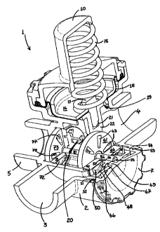
With respect to Figure 5 there is provided a valve assembly generally
indicated by arrow 1. The valve assembly 1 has a valve body 2 having an
inlet connecting portion 3 which in most applications is connected via a
conduit (not shown) to a high pressure ("HP") mains water supply (not
shown). The valve body 2 also has an outlet 4 which is connected via a
conduit (not shown) to a low pressure ("LP") fluid system in the form of a
hot water cylinder (not shown).
The valve body 2 also has a relief outlet connecting portion 5. The relief
outlet connecting portion 5 is connected to a conduit (not shown) which
may connect to a drain, or alternatively lead to an area suitable for
21
SUBSTITUTE SHEET (RULE 26)
CA 02404875 2002-09-24
WO 00/58653 PCT/NZ00/00040
draining water from the valve assembly 1.
The valve body 2 also has an opening in the region indicated by arrow 6
which allows for access to many of the components of the valve assembly 1
housed within the valve body 2. The access opening 6 is closed via a
retainer cap 7. The valve body 2 also has a top opening in the region
indicated by arrow 9 which also allows for access to the components housed
within the valve body. The opening 9 is closed via a spring cap 10 which is
connected to the valve body 2 via a clamp ring 11.
In general, the retainer cap 9 and clamp ring 11 are threadably connected
to the valve body 2.
Fi"res 6, 7, 14 and 15
A. Construction of Valve Assembly.
With respect to Figure 6 - 7 there is shown a preferred embodiment of
valve assembly 1 has a spring 15 which has its upper portion located
within the spring cap 10. The lower end of the spring 15 forces down on a
piston 16. The lower end of the spring 16 is located on the top of the piston
16 via the head of a trilobe screw 17. The bottom surface of the piston 16
sits on a diaphragm 18 which seals the top opening 19 of the valve
chamber 20 formed by the valve body 2.
The trilobe screw 17 passes through apertures in the piston 16 and
diaphragm 18 and threadably engages a central aperture 21 in a con rod
22.
The con rod 22 has an aperture 23 having a bearing surface in which a
journal 24 extending from a drive base 25 locates. The drive base 24 has
two drive dog lugs ("DD lugs") 26 and 27 extending in the same direction as
22'
SUBSTITUTE SHEET (RULE 26)
CA 02404875 2002-09-24
WO 00/58653 PCT/NZOO/00040
journal 24. DD lugs 28 and 29 are located on the opposite side of the drive
base 25 but have the same spatial position with respect to drive base 25 as
DD lugs 26 and 27.
The drive base 25 also includes an aperture 30 having a bearing surface for
receiving an axle 31.
The drive base 25 is retained on the con rod 22 via a drive lock plate 32.
The drive lock plate has apertures 33 and 34 which are configured to snap
lock onto DD lugs 26 and 27 so that the distal portions of the DD lugs 26
and 27 can still extend through apertures 33, 34. The drive lock plate 32
also has a lugged cap portion 39 designed to snap fit onto the distal end of
journal 24 once it has been received in aperture 23 of con rod 22.
The drive lock plate 32 also has an aperture 37 having a bearing surface
for receiving the axle 31. The drive lock plate also has a DD lug 35
extending from its surface in the same direction as those of DD lugs 26 and
27 of the drive base 25 when located in apertures 33, 34. The drive base 25
also has a further DD lug 36 which extends in the same direction as DD
lugs 28, 29. DD lug 36 is in alignment with DD lug 35 when the drive base
25 and lock plate 32 are connected via journal 24, lugs 26, 27 and axle 31.
The distal end portions of DD lugs 26, 27 and 35 locate in appropriately
positioned recesses 40, all situated in a valve head in the form of a ceramic
"rotating" inlet port ("RIP") disc 41. The fit of the lugs 26, 27 and 35 into
the recesses 40 in RIP disc 41 is such that any lateral movement of the
lugs will cause a corresponding lateral movement of the disc 41. The RIP
disc 41 also has a centrally positioned aperture 42 including a bearing
surface for receiving axle 31. Accordingly, the ceramic RIP disc 41 is
designed to rotate about axle 31 when the DD lugs 26, 27 and 35 are
23
SUBSTTTUTE SHEET (RULE 26)
CA 02404875 2002-09-24
WO 00/58653 PCT/NZ00/00040
caused to move by the con rod 22 and its associated piston 16. The ceramic
RIP disc 41 also includes a number of inlet ports 43 which allow for the
travel of water through the disc 41.
A "stationary" inlet ("SI") ceramic disc 44 has a central aperture 45 with a
bearing surface for receiving axle 31. The SI disc 44 is positioned on axle
31 so that it abuts the RIP disc 41.
The SI disc 44 includes three recesses 45 on the opposite face to that which
abuts RIP disc 41. The recesses 45 -receive lugs 46 which extend from a
stop plate 47. The fit of the lugs 46 into the recesses 45 is tight, such that
there is no movement of SI disc 44 relative to stop plate 47. The SI disc 44
includes a number of fluid inlet apertures 50. Stop plate 47 itself has a
recess 48 located on the opposite surface to that adjacent the SI disc 44.
The recess 48 receives a lug 49 which extends from the inner surface of the
retaining cap 7. The fit of recess 48 about lug 49 is such as to prevent any
movement of the stop plate 47 relative to the cap 7. Furthermore, lug 49
and recess 48 are positioned so as to not be coaxial with respect to axle 31
to prevent any rotation of stop plate 47 relative to the valve body 2.
The stop plate 47 is configured so that the majority of its surface area does
not abut the outer surface of SI disc 44. The purpose of this gap is to allow
for HP mains water to have access to the inlets 50 in SI disc 44.
A fluid tight seal is effected between the valve body 2 and the retainer cap
7 via 0-ring 51 which locates in an annular groove 52 on the inside edge of
the opening access 6 of the valve body 2. The 0-ring 51 also abuts against
shoulder and ridge portions 53 and 54 of retainer cap 7. The stop plate 47
also includes an aperture 55 having a bearing surface of which receives one
end of the axle 31. To effect a seal between the SI disc 44, stop plate 47
24
SUBSTITUTE SHEET (RULE 26)
CA 02404875 2002-09-24
WO 00/58653 PCT/NZ00/00040
and the axle 31, an 0-ring 56 is located in an annular groove 57 in SI disc
44 so it can abut axle 31. The outer surface of 0-ring 56 is abutted by the
raised ends 58 of aperture 55.
The SI disc 44 has a radial flange 60 which effectively increases the
surface area of the "non-sealing" face of the SI disc 44 which is opposite
that which abuts the RIP disc 41. The radial flange 60 effectively forms a
shoulder which can abut against an internal chamber wall 61 of valve body
2 and a shoulder 62 on valve body 2.
The pressure of the HP mains water supply can vary. To compensate for
this the ends of lugs 46 and raised ends 58 of stop plate 7 (i.e. the portions
of stop plate 57 closest to SI disc 44) do not contact the SI disc 44 unless
little or no pressure is being applied on the SI disc 44 by the incoming HP
water. This clearance is achieved as the length of axle 31 holds stop plate
47 away from the SI disc 44. Although, as a result of this clearance the SI
disc 44 can move back in the direction of arrow 64 until it hits the ends of
lugs 46 and raised ends 58 of plate 47. The purpose of this clearance is so
that at times when the mains water pressure is below its maximum, the
frictional force between the sealing faces of the RIP and SI discs 41, 44 is
minimized to only that necessary to effect a watertight seal.
When higher pressures are experienced in the mains water supply, and
hence on the SI disc 44, the maximum frictional force encountered between
the sealing faces of the RIP and SI d.iscs 41, 44 can be limited by radial
flange 60 abutting wall 61 and shoulder 62. The flange 60 thereby
prevents any further movement of SI disc 44 in a forward direction as
indicated by arrow 65 said movement being caused by the inward force
exerted on the SI disc 44 by the pressure of the incoming HP water.
SUBSTITUTE SHEET (RULE 26)
CA 02404875 2002-09-24
WO 00/58653 PCT/NZOO/00040
To prevent any water leaking into the chamber round the outside edge of
SI disc 44, an 0-ring 65 is located in a groove 66 in internal chamber wall
61 and shoulder 63 of the valve body 2.
The distal portions of DD lugs 28, 29 and 36 locate in appropriately located
recesses 70 situated in a rotating relief port ("RRP") disc 71. The fit of the
DD lugs 28, 29 and 36 into the recesses 70 in RRP disc 71 is such that any
lateral movement of the lugs will cause a corresponding lateral movement
of the disc 71. The RRP disc 71 also has a centrally positioned aperture 82
including a bearing surface for receiving axle 31. Accordingly, the ceramic
RRP disc 71 is designed to rotate about axle 31 when the DD lugs 28, 29
and 36 are caused to move by the con rod 22 and its associated piston 16.
The RRP disc 71 also includes a number of relief ports 72 which allow for
the escape of water through the disc 71.
The RRP disc 71 has the same configuration as that of RIP disc 41.
A stationary relief ("SR") ceramic disc 73 has a central aperture 74 with a
bearing surface for receiving axle 31. The SR disc 73 is positioned on axle
31 so that it abuts the RRP disc 71.
The SR disc 73 includes three recesses 75 on the opposite face to that
which abuts RRP disc 71. The recesses 75 receive stop pins 76 which
extend from recesses (not shown) in the valve body 2. The fit of the stop
pins 76 into the recesses in the valve body 2 is tight such that there is no
room for lateral movement between the pins and valve body 2. The fit of
the stop pins 76 into the recesses 75 in the SR disc 73 is also tight, such
that there is no movement of SR disc 73 relative to stop pins 76. The SR
disc 73 has a number of relief outlet apertures 77. The relief outlets 77
are positioned adjacent outlets 500 in valve body 2 so that any water
26
SUBSTITUTE SHEET (RULE 26)
CA 02404875 2002-09-24
WO 00/58653 PCT/NZOO/00040
flowing through outlets 77 can exit the valve assembly 1 via outlet
connecting portion 5.
The SR disc 73 has, with the exception of annular groove 79, substantially
the same configuration as that of the RRP disc 71 and RIP disc 41.
A fluid tight seal is effected between the valve body 2 and the SR disc 73
via an 0-ring 78 which locates in an annular groove 79 in disc 73. A seal
between the SR disc 73 and the axle 31 is effected via an 0-ring 80 which
locates in an annular groove 81 in the SR disc 73 so it can abut axle 31.
It should be appreciated by those skilled in the art that 0-rings 78 and 80
should be selected so that they have sufficient strength to withstand any
over pressure from the mains water supply not taken by the radial flange
60. As if 0-rings 78 and 80 fail the RIP disc 41 can move away from SI
disc 44 so there is no fluid-tight seal between the sealing faces of those
discs, and the valve will be compromised.
The recesses 75 in the valve body 2 in which the stop pins 76 locate, are
positioned so that the stop pins 76 position SR disc 73 so that its relief
outlets 77, have a different spatial orientation with respect to the valve
body 2 to that of the fluid inlet apertures 50 of the SI disc 44. This is to
ensure that when the inlet ports 43 of the RIP disc 41 are aligned with the
fluid apertures 50 in the SI disc 44, the relief ports 72 of the RRP disc are
not aligned with the relief outlets 77 of SR disc 73; and vice versa.
Figure 8
B. Valve Assembly Operation
With respect to Figure 8 there is shown the valve assembly 1 in its "fully
open" position.
27
SUBSTITUTE SHEET (RULE 26)
CA 02404875 2002-09-24
WO 00/58653 PCT/NZ00/00040
For ease of reference only, the SI and RIP discs 44, 41 will now be
collectively referred to as the "inlet discs", and the SR and RRP discs 73, 71
will now be collectively referred to as the "vent discs".
When the valve assembly 1 is in its open position as is shown in Figure 8,
the spring 15 is in a relaxed position (i.e. having minimal potential energy)
the spring 15 biases the piston 16 and diaphragm 18 to the their down
most positions as shown. When the piston 16 and diaphragm 18 are in
their down most positions the con rod 22 via the DD lugs 26, 27 and 35 has
positioned the RIP disc 41 so that its inlet ports 43 are aligned with the
fluid inlet apertures 50 in the SI disc 44 (which is shown partially cut
away so as to reveal RRP disc 41 in more detail). Accordingly, the inlet
discs 41, 44 are in the "open position". Conversely, the con rod via DD lugs
28, 29 and 36 has the RRP discs 71 oriented so that relief ports 72 are not
aligned with the relief outlets 77 of SR discs 73 (i.e. the vent discs are in
the "closed position").
When the inlet discs are in their "open position", water 90 is able to enter
the valve assembly 1 from the HP mains supply via a conduit (not shown)
connected to inlet connecting portion 3 of the valve body 2. The HP water
then passes through a neck 91 formed between the internal chamber wall
61 and the outside wall in the region indicated by arrow 92. The incoming
HP water 90 then passes through inlet apertures 50 in SR disc 44. As the
HP discs are aligned water 90 is able to pass through inlet ports 43 of RIP
disc 41 and into an internal valve chamber 20. As the vent discs 71, 73 are
in the "closed position" (i.e. non-aligned) the HP water 90 travels through
the internal chamber 20 and out via the outlet 4 via a conduit (not shown)
to enter an LP hot water cylinder (not shown).
When the diaphragm is in its "fully open" position the calculated spring
28
SUBSTITUTE SHEET (RULE 26)
CA 02404875 2002-09-24
WO 00/58653 PCT/NZOO/00040
load is substantially 123.9N on piston 16 and this requires a pressure of
approximately 67.7KPA (10PSI) in the internal chamber 20 and hence the
hot water cylinder before it moves upwardly.
Figure 9
Once the hot water cylinder of the LP fluid system has been filled with
water, the increased pressure in the cylinder causes water from within the
cylinder to enter the valve chamber 20. This causes the diaphragm 18 and
associated piston 16 to move in an upwards direction against the biasing
force of spring 15 to the "set pressure" position shown in Figure 9.
When the diaphragm is in its "set pressure" position as shown in Figure 9
both the inlet discs and vent discs are in their "closed positions" (i.e. not
aligned). Accordingly, there is no water movement in or out of the valve
assembly 1.
In the "set pressure" system the calculated spring load on piston 16 is
substantially 137.3 N and this requires a pressure of approximately
75KPA (11PSI) in the internal chamber 20/hot water cylinder.
Figure 10
With respect to Figure 10 the diaphragm 18 and associated piston 16 have
moved even higher within the valve assembly 1 to a "initial vent" position.
In the "initial pressure" position, the con rod 22 and associated DD lugs 28,
29 and 36 have oriented RRP disc 71 so that its relief ports 72 are very
slightly aligned with the relief outlets 77 in SR disc 73.
Conversely, con rod 22 when in the "initial-vent" position has the RIP disc
41 oriented so that the inlet discs are in their "closed position" (i.e. non-
aligned).
29
SUBSTITUTE SHEET (RULE 26)
CA 02404875 2002-09-24
WO 00/58653 PCT/NZOO/00040
In the "initial pressure" position the calculated spring load on piston 16 is
substantially 142.3N and this require a pressure of approximately 77.7
KPA (11.42PSI) in internal chamber 20/hot water cylinder.
Figure 11
With respect to Figure 11 the valve assembly is shown with the diaphragm
18 and associated piston 16 in their top most " fully vented" position.
In this position, the con rod 22 and its associated lugs 28, 29 and 36 have
oriented RRP disc 71 so that its relief ports 72 are fully aligned with the
relief outlets 77 of SR disc 73 (i.e. the vent discs are in the "open
position").
When the con rod 22 has this position within the valve assembly 1, the
orientation of the RIP disc 41 is such that the inlet discs still remain in a
"closed position" (i.e. non-aligned).
Accordingly, water 90 flows from the hot water cylinder of the LP fluid
system and out through relief ports 72 and relief outlets 77 in the vent
discs and out of the valve assembly 1 via relief outlet connecting portion 5.
When the valve assembly is in the "fully vented" position the calculated
spring load is substantially 155.7N and this requires a pressure of
substantially 85KPA (12.5 PSI) in internal chamber 20 and hence the hot
water cylinder.
The valve assembly 1 will remain in the "fully vented" position shown in
Figure 11 until the pressure of the LP fluid system drops to below
substantially 75 KPA (11PSI).
It will be appreciated by those skilled in the art, that the effect of
operating
any taps connected to the LP fluid system will cause the valve assembly 1
to function in a substantially similar manner to that already described
SUBSTITUTE SHEET (RULE 26)
CA 02404875 2002-09-24
WO 00/58653 PCT/NZOO/00040
with respect to Figure 2.
F47ure 12
With respect to Figure 12 there is shown a cutaway view of a valve
assembly 100 substantially the same as that shown in Figures 5 - 11. The
valve assembly 100 differs however in that it also has a ratchet arm 101
associated with con rod 22. The ratchet arm 101 being made of a resilient
material and constructed such that it exerts a force on a pawl portion 104
of the ratchet arm 101. The pawl portion 104, has teeth 103 adapted to
engage the teeth 102 on con rod 22, to control movement of the con rod 22
in an upward direction.
The ratchet arm 100 and its associated pawl teeth 103 are biased onto the
teeth 102 of the con rod 22 such that the teeth 102, 103 remain engaged
until a force greater than the biasing force of the ratchet arm has been
applied to the con rod 22 via the piston 16.
The force required to disengage the teeth 102, 103 will generally be the
force exerted by the piston 16 and diaphragm 18 (both not shown in Figure
12) when the pressure in the internal chamber 20 is slightly less than the
recommended maximum pressure of the LP fluid system. For example, if
the recommended maximum pressure of the LP hot water cylinder is 11PSI
a pressure of greater than 10PSI within the internal chamber 20 should
result in the piston 16 exerting a sufficient force onto the con rod 22 to
disengage the teeth 102, 103.
The purpose of the ratchet arm 100 is to help prevent any normal "back
flow" pressure from the LP fluid system causing the valve assembly to shut
off the HP inlet flow via the inlet discs, when the hot water cylinder is
still
empty.
31
SUBSTITiTTE SHEET (RULE 26)
CA 02404875 2002-09-24
WO 00/58653 PCT/NZ00/00040
In addition, a further effect of the ratchet arm 101 is to cause the inlet
discs to substantially only exist in either the "fully open" or "fully closed"
position. Consequently, water exiting the LP fluid system via a tap will
always remain at substantially full pressure, as the inlet ports are always
in their "fully open" position - when there is a reduced pressure in the hot
water cylinder (i.e. the amount of mains water entering the system will not
be reduced by partially aligned ports/inlets).
Fiaures 13 and 14
Figure 13 illustrates an exploded view of the components of the valve
assembly described in relation to Figures 6 - 11. Figure 14 illustrates for
clarity from a different perspective some of the components shown in
Figure 13.
Example 1
In situations where the mains water supply to the hot water cylinder is
turned off and where the power to the hot water cylinder is also turned off
(such as may occur at a holiday home): due to thermal contraction a
negative pressure in the cylinder may result. To equalise this negative
pressure air or water must enter the cylinder to avoid an implosion from
occurring. In this situation it is envisaged air or water may enter the LP
cylinder via:
a) Utilising a mains supply control valve engineered to be leaky so that
it can allow water to enter the LP fluid system; or
b) Positioning a pressure sensitive valve (e.g. a poppet valve) so that it
is located upstream of the valve assembly of the present invention,
but downstream of the mains supply control valve - so that it can
32
SUBSTITUTE SHEET (RULE 26)
CA 02404875 2002-09-24
WO 00/58653 PCT/NZ00/00040
allow air to enter the LP fluid system; or
c) Utilising a relief valve in accordance with the present invention, on
the outlet of the hot water cylinder such as described for Figure 13
above.
Example 2
As an alternative to the ratchet arm arrangement shown in Figure 12, the
spring 15 may be engineered so that its calculated spring load in its
relaxed position is slightly less than the recommended maximum pressure
of the hot water cylinder - (which is the pressure at which the valve moves
to its set pressure position shown in Figure 13). Accordingly, the piston
and con rod 22 will not move until this pressure has been released.
In general, it is envisaged this may be achieved by selecting a relatively
long spring so that there is only a small degree of variation between the
potential energy of the spring between its "fully open" and "set pressure"
positions within the valve assembly of the present invention.
Aspects of the present invention have been described by way of example
only and it should be appreciated that modifications and additions may be
made thereto without departing from the scope of the appended claims.
33
SUBSTITUTE SHEET (RULE 26)