Note: Descriptions are shown in the official language in which they were submitted.
CA 02404981 2005-11-14
27527-41
~
-1-
Gunter Reichel, D-35232 Dautphetal
Shower Partition and Shaped Section for the Same
Description
Shower partitions usually possess a profiled frame which surrounds the shower
chamber and is adjustably fixed to a room wall, for example by means of
lateral
profiled elements, and is firmly attached via a profiled base unit to the edge
of a
shower basin or bathtub. The doors are in the form of sliding doors or swing
doors
and have glass or plastics panes that may be enclosed in frame profiles.
Sealing
means between the profiled door and frame elements prevent the escape of water
from the interior of the shower cubicle or bathtub.
Some of the profiled frame and door elements are of considerable width, which
fact
can be unsatisfactory from an esthetic point of view and reduces the amount of
transparent area available. Thus in order to allow as much light as possible
to pass
into the shower cubicle from outside and to make the frame structure
inconspicuous as a whole, attempts are being made to reduce the profiled frame
to
as few elements as possible and to avoid the necessity of a door frame by
implementing the glass or plastics panes themselves as wall elements or door
elements. Thus, for example, a pane of glass has been hingedly attached to a
profiled wall element by means of a lateral profiled unit. A profiled sealing
strip
carrying a magnetic strip is mounted onto the closing edge of said glass pane,
whilst its bottom edge is provided with only a narrow antisplash strip.
A shower partition disclosed in DE 295 04 715 U1 has a profiled frame composed
of a lower base profiled element fixed horizontally on the edge of a shower
basin
and of lateral profiled frame elements between which a swing door is mounted
for
CA 02404981 2002-10-01
rotation about an axis offset toward the door center. The door has profiled
joining
elements that are mounted laterally on the door edges and engage the profiled
frame elements in close fit when the door is closed so that optically only one
uniform profiled element will appear. The pivot bearings are likewise not
directly
visible. A bottom pivot bearing is hidden below the profiled base unit while a
top
pivot bearing is attached to the top edge of the door by means of a short
accommodating head only. Other structures of glass dispense entirely with
profiled
frame and door elements. In the top and bottom regions of the door side edges,
only individual hinges are situated which are mounted on a room wall or a
glass
partition element. However, a problem here is that the total weight of the
relative
heavy glass doors must be carried by the top hinges so that high wear on the
joints
and possibly also glass fracture may result. Subsequent width adjustment of
the
shower partition to adapt the latter to different room dimensions is possible
either
not at all or only within narrow limits via the fittings of the glass
partition elements.
This is not always adequate.
In order that the bottom edge of the door or a profiled sealing strip fixed
thereto will
not hinder opening and closing of the shower cubicle, swing doors have been
mounted such that they are vertically displaceable in addition. DE 42 02 757
C2
discloses in this respect a guide strip to be fixed on the side near the wall
in order
to receive a displaceable profiled bar. To the latter, a door is hingedly
attached
which can be moved from an upper to a lower position, whereby inter-engaging
profiled sealing strips effectively prevent the escape of shower water. A
lifting
device actively connected to the shiftable profiled bar via a cable or a lever
arm
makes it possible to raise the door so that it can be freely swung past the
profiled
sealing strips. In order to reduce the force required to raise the door, a
pneumatic
spring absorbs the major part of the door. Assembly and installation require
quite
an effort and expenditure. The guide strip and profiled bar are relatively
broad,
which considerably spoils the overall appearance of the frame or shower
partition.
It is an object of the present invention to reduce the number of profiled
elements of
a shower partition to a minimum and to guarantee permanently reliable
precision
bearing and sealing of the door elements. Adjusting means are to be available
for
adaptation of the shower partition to different room dimensions and
installation
CA 02404981 2005-06-10
27527-41
-3-
conditions. Shower partitions made with the profiled
elements shall be of simple structure and cheap to produce.
It is likewise desired to install and use them both quickly
and easily.
According to one aspect of the present invention,
there is provided a shower partition comprising a profiled
unit for a swing door, the profiled unit having a profiled
element that extends over at least part of the vertical
extension of the swing door and that has lateral grooves for
accommodating a door leaf or door leaves of the swirig door,
the profiled element being mounted at ends thereof by means
of first and second pivot bearings for rotation about a
vertical axis, characterized in that two partial leaves form
the swing door together with the profiled unit, in that the
profiled unit is provided on either side with a longitudinal
groove for accommodating the partial leaves and in that the
partial leaves are positionally adjustable relative to each
other in at least two spatial directions within the
longitudinal grooves of the profiled unit.
In a profiled unit for a swing door of a shower
partition, which door is mounted for rotation in pivot
bearings about a vertical axis displaced toward the center
of said door, the invention provides that the profiled unit
extends between said pivot bearings over at least part of
the vertical extension of the swing door and accommodates a
door leaf which is split in a direction parallel to said
rotation axis. Thus except for the profiled unit disposed
between the door leaf parts, the swing door requires no
other profiled frame or edge members to be placed in or on
lateral wall parts. The size of the profiled door element
between the pivot bearings is reduced to a minimum, whilst
the free door area allows plenty of light to penetrate into
the interior of the shower cubicle. Since the pivot
CA 02404981 2005-06-10
27527-41
-4-
bearings are flush with the top and bottom of the profiled
unit, no further structural components or other visible
obstructions will disturb the appearance.
In another aspect of the invention, a profiled
unit for a shower partition swing door of the aforementioned
type, the invention provides, opposite a longitudinal groove
in the profiled unit, a second longitudinal groove in which
another continuous flat element can be inserted which is of
the same shape as, or a similar shape to, said door leaf.
The swing door mounted in the profiled unit can thus in a
surprinsingly simple manner be broadened by, say, the
breadth of a side member, without requiring the use of any
additional or supplementary profiled units or frame parts.
This results in interesting designs of shower partitions
which may also be conveniently installed over shower-:ubs or
bathtubs.
A significant feature of the invention is that
partial leaves forming the door leaf and held on either side
in grooves of the profiled unit are positionally adjustable
in at least two dimensions relative to each other wit:hin the
longitudinal grooves of the profiled unit. One result of
this is that it is possible to subsequently alter the
breadth of the swing door, ie the entire shower partition
can be individually adapted to given room dimensions.
Since, if required, both door leaves can be adjusted, the
adjustment range is extremely large, although the entire
door includes only a single, relatively narrow profiled
unit. Another result is that the door leaves, and
particularly the door leaf edges, can be adapted to the run
of the room walls. If these are for example slightly
inclined or sloping, which is not rare, the door leaf on the
side near the wall can be appropriately positioned, while
CA 02404981 2005-06-10
27527-41
-5-
the partial leaf affording main entrance into the shower
cubicle can be independently adjusted.
According to another aspect of the present
invention, flat elements are insertable into or attachable
to a profiled element of the profiled unit, at the front
and/or rear thereof, primarily by means of frictional and/or
form-fitting connections. This opens opportunities for
variegated designs, specifically for the use of differently
colored and/or mirrored flat elements to match surrounding
furnishing and for the use of supplementary functional
elements such as soap dishes, handgrips, hooks, rotary
handles and the like, which can be subsequently fitted
inside or outside the shower partition as desired.
Preferably the profiled unit of the invention is
used in shower partitions for attachment to a shower basin,
showertub or bathtub. At least one such profiled unit is
mounted, in a bottom pivot bearing so that the entire weight
of the swing door is absorbed vertically, and thus
substantially without shearing or cross forces, by the edge
of the basin and via the same by the floor. In this manner
permanently reliable and precise support is guaranteed.
Since the partial leaves of the swing door can be
positionally adjusted relative to each other and can be
individually adapted to the room dimensions, there is always
optimal leakproofing against splash water. The shower
partition exhibiting only one profiled unit per door is very
simply constructed and can be easily set up even by
untrained personnel.
According to still another aspect of the
invention, whereby for affording base support for the
profiled unit together with its adjustable pivot bearing on
a supporting surface, eg the floor or an edge of a shower
CA 02404981 2005-06-10
27527-41
-5a-
basin or showertub, a mounting or supporting plate is
provided which can be positionally adjusted and locked for
alignment of the door. Preferably adjusting means are
present which have screw-threaded elements for acconTnodation
of adjusting and locking screws or alternatively articulated
suckers for compensating inclines and angular or height
deviations. Once the correct position of the swivel joint
and thus of the door has been achieved by said adjustment,
this state can be secured by, say, adhesive bonding, and any
gap found underneath the mounting plate can be sealed up
with the adhesive or a silicon compound.
For the purpose of raising and lowering a shower
partition door, the invention further provides, that the
bottom pivot bearing carries a spring assembly on which the
weight of the door rests and which is manually preloadable,
specifically by means of a handwheel for adjustment of the
position of an eccentric, whereby a cable suspended
therefrom contracts or releases a compression spring mounted
between two inter-rotatable sleeves. This extremely simple
design allows for easy raising and lowering of even very
heavy doors.
Further features, details, and advantages of the
invention may be gathered from the wording of the claims and
from the following description of working examples bearing
reference to the drawings in which:
Fig.1 is a front view of a shower partition,
Fig.2 is a horizontal sectional view of the shower partition
of Fig.1,
Fig.3 is a partial cross-sectional view of a swing door
containing a profiled unit,
CA 02404981 2005-06-10
27527-41
-5b-
Fig.4 is a partial cross-sectional view of another swing
door with a profiled unit,
Fig.5 is a partial cross-sectional view of another profiled
unit,
Fig.6 is a partial cross-sectional view of yet another
profiled unit,
CA 02404981 2002-10-01
- G-
Figs.7a are longitudinal section views of a door assembly comprising a
and 7b profiled unit of Fig. 6, in two different door positions,
Figs.8a are enlarged partial views corresponding to Figs. 7a and 7b,
and 8b
Figs.9a are partial rear views of a profiled unit according to Fig. 6 in two
and 9b different settings corresponding to the positions of Figs. 7a, 8a and
7b, 8b, respectively.
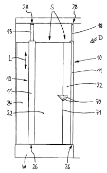
Fig. 1 shows, for example, a shower cubicle or shower partition D for a corner
shower, which is mounted on the top edge of a showertub or shower basin W and
has two swing doors S each rotatably mounted in a bottom bearing 26 and a top
bearing 28. Each of the doors S has a split door leaf 22, 24 of glass and a
profiled
unit 10 connecting the partial leaves 22, 24. The latter extends between the
pivot
bearings 26, 28 preferably over the entire height of swing door S and also
somewhat beyond. However, the profiled unit 10 may, if required, end flush
with the
top edge of door S. It is important to ensure that it is parallel to a
rotation axis A
which is displaced toward the center of the door due to the fact that the door
leaf
22, 24 is divided into two parts. This makes it possible to open door S even
where
there is little room, eg if room fittings, such as cupboards, wash basins or
the like
should obscure part of the front of the door.
The partial leaves 22, 24 accommodated by the profiled unit 10 on either side
thereof form, as shown in Fig. 2, in the side areas of corner shower D, a
substantially plane door surface which, in the direction of the closing edges
71 of
doors S, is curved to assume the same or similar shape as the shower basin W
and
comprises no further profiled edge pieces except for profiled units 10 so that
the
frame optics are reduced to a minimum and plenty of light reaches the interior
of
shower cubicle D. Each door leaf 22, 24 may carry handling means 70 at its
closing
edge 71 where magnetic elements (not shown) can be enclosed in closing edges
71 of the door S or in handles or parts thereof extending flush therewith, in
order to
keep the swing door S sealed in its closed position. Where the shower basins W
are differently shaped, the door leaves or partial leaves 22, 24 may form an
overall
plane or even curved door surface or they may be at an angle to each other,
depending on the room characteristics and the shape of the basin.
CA 02404981 2002-10-01
_7,
As the doors S are opened outwardly via the handles 70, the partial leaves 22
adjacent each other swing outwardly while the partial leaves 24 acting as side
members of shower partition D swing inwardly. Alternatively, it is possible to
open
the doors inwardly so that their partial leaves 24 swing outwardly. The easy-
to-
clean swing doors S permit convenient access to the interior of the shower
partition
D at all times.
In the embodiment shown in Fig. 3 the profiled unit 10 includes a single-piece
profiled element 11 which has an approximately oval or lenticular cross-
section and
a flattened rear portion 31. At the lower and upper ends of the profiled unit
10 there
are recesses 16 in the end faces of the profiled element 11 to accommodate
pivot
bearings 26, 28. The bottom pivot bearing 26 (not shown) is completely hidden
by
the profiled unit 10 or its profiled element 11, ie it is not visible from
outside.
Bearing parts (not shown) of the pivot bearing 26 have inclined slip planes
which,
as the swing door S is rotated about axis A, force the profiled unit 10 to
rise during
the opening operation and to fall when the door is closed, without damaging
the
bottom edges of the door. In its closed position, door S is held securely over
the
edge of the basin so as to form a seal therewith.
In order to brace profiled unit 10 at its top end, where the pivot bearing 28
is
accommodated in recess 16, it is preferably held by a bracket (not
illustrated) fixed
to a wall R of the room, for example a bathroom wall. Alternatively, as shown
in
Fig. 1, a telescopic extension 18 may be provided in the upper recess 16
reaching
to below a ceiling or a ceiling-like projection C where it engages the pivot
bearing
28. It is important to ensure that the profiled unit 10 functioning as a
continuous
hinge has its upper end in such a position that the pivot bearings 26, 28 are
in
vertical alignment along rotation axis A.
It will be seen from Fig. 3 that two longitudinal grooves 12, 14 are provided
in the
profiled element 11 of the profiled unit 10 for accommodation of the partial
leaves
22, 24 at the side, the width of said grooves being approximately equal to the
thickness of the partial leaves 22, 24. In a longitudinal direction L of the
profiled
element 11, there are provided - preferably at equidistant intervals - fixing
or
CA 02404981 2002-10-01
locking screws 32 which pass through each longitudinal groove 12, 14 for
engagement of screw-threaded bores 33 within the profiled element. In
accordance
with the arrangement of the clamping screws 32, each partial leaf 22, 24
inserted in
longitudinal groove 12, 14 assigned thereto is provided, along its
longitudinal edge
23, with round or oblong bores 25 (at right angles to the longitudinal
direction L),
the diameter or length and/or width of which being greater than the outside
diameter of the locking screws 31. If these screws are firmly tightened, the
partial
leaves 22, 24 are sealingly locked to the profiled element 11 within the
longitudinal
grooves 12, 14. On the other hand, as the screws are loosened, the position of
the
partial leaves 22, 24 can be adjusted - within the limits dictated by the
bores 25 and
the depth of groove T - relative to each other and relative to the profiled
unit 10
supported by pivot bearings 26, 28.
A decisive advantage of this arrangement is that the swing doors S can be
adapted
to different local conditions because each door leaf 22, 24 lends itself to
width
adaptation due to ist two-parts design. Alternatively, the vertical and
lateral
positions relative to the edge of the basin or relative to room wall R may be
separately optimized for each partial leaf 22, 24 so that the shower partition
D can
be installed and adjusted as a water-tight unit with or without the use of
additional
profiled sealing strips P attached to the glass edges of the partial leaves
22, 24 or -
as indicated in Fig. 2 - attached to room wall R. The simply designed
adjustment
means are easy to handle. Another advantage is that both partial leaves 22, 24
can
be mutually adjusted within the profiled unit 10, ie the entire door S covers
a very
large width range based on the size of the relatively narrow profiled unit 10.
Consequently the overall dimensions of the shower partition can be readily
changed and individually adapted to often very different room characteristics.
For preventing the locking screws 32 from being visible or accessible from the
outside, a cover strip 38 is let into the rear surface 31 of the profiled
element 11,
which strip is held in a recess 35 so as to be frictionally locked and form-
fitting and
be flush with the surface of the rear side 31 of the profiled element 11.
In order to support the profiled unit 10 at the bottom and the adjustable
pivot
bearing 26 disposed therein, a base plate or support plate 50 may be provided
(cf
Figs. 7a, 7b and 8a, 8b), which engages a bottom supporting surface, eg the
floor
or an edge of a shower basin or showertub, and which can be adjusted and fixed
for alignment of door S. Preferably the plate 50 comprises screwing elements,
eg
an adjusting screw 51 and a grub screw 52 in order to be able to compensate
for
inclines and general angular or height deviations in an advantageous and
precise
manner. Once the correct position of door S has been achieved by adjustment of
the pivot bearing 26, this state can be secured, for example by adhesive
bonding.
Any gap found underneath the base plate 50 can be closed and sealed off with
adhesive or with a silicon compound.
In another embodiment, the profiled element 11 of the profiled unit 10
includes a
plurality of component parts. According to Fig. 4 it has a main profiled
member 40
comprising a central channel 41 and clamping surfaces 42 at the rear and also
two
profiled clamping elements 43, 44, each of which is locked in the main
profiled
member 40 by means of its hooked ends 45 pointing toward the rotation axis A.
Lateral longitudinal grooves 12, 14 accommodate the partial leaves 22, 24
between
the main profiled member 40 and the profiled clamping elements 43, 44. Locking
screws 32 are screwed into main profiled member 40 at equidistant intervals in
the
longitudinal direction L, which member may have special screw-threaded inserts
34
for this purpose. Several sealing elements 47 are provided on the clamping
surfaces 42 of the main profiled member 40 and also on the insides of the
profiled
clamping elements 43, 44 in order to seal the door leaf parts 22, 24 from the
profiled element 11. Hinging of the profiled unit 10 or the main profiled
member 40
is made possible by the recesses 16 provided in central channel 41 for the
pivot
bearings 26, 28 or the extension 18, in which case at least one screw 19
provided
between the profiled clamping elements 43, 44 serves the purpose of fixing the
necessary draw-out degree of extension 18.
The mode of operation of the two-part profiled element 11 corresponds to that
of
the integral profiled unit, ie by loosening the screws 32 it is possible to
adjust the
positions of the partial leaves 22, 24 within the longitudinal grooves 12, 14
relative
to each other and relative to the profiled parts 40, 43, 44. Tightening the
screws 32
causes the profiled clamping elements 43, 44, tiltably mounted by means of
their
hooked ends 45, to be pulled against the clamping surfaces 42 of the main
profiled
CA 02404981 2002-10-01
CA 02404981 2002-10-01
_ / 0
member 40 and thus to be firmly pressed against the partial leaves 22, 24. A
flat
element clipped into the rear 31 of profiled element 11 to form a cover strip
38
conceals clamping screws 32 and locking screws 19. For this, the profiled
clamping
elements are provided at the rear with clamp springs 46 and with bearing
surfaces
48.
The longitudinal grooves 12, 14 of the profiled unit 10 are preferably in line
in a
single plane. They may alternatively be in staggered relationship in a row and
fixed
by a common clamping device, whereby the profiled unit 10 can be made even
narrower. Another possibility is that the longitudinal grooves 12, 14 in the
profiled
unit 10 are at a preferably obtuse angle to each other so that door S has an
angular
form due to their partial leaves 22, 24. Curved shapes are also possible.
For technical and/or esthetic reasons, the front of the profiled unit 10 may
be
provided with decorative or colored strips in the form of flat elements 30
accommodated in recesses 49 at the profiled element 11 or at the main profiled
member 40 where they are tensionally locked and/or interlocked. Each flat
element
30 can, over its entire length or if necessary over portions thereof be in
reentrant,
flushed, or projecting relationship with said profiled element 11 or the main
profiled
member 40. Another very advantageous feature comprises the possibility of
attaching to the flat elements 30, 38 any desirable decorations, labels or
even
fittings such as soap dishes, towel holders, mirror holders, rotary handles
and the
like.
In the embodiment shown in Fig. 5, the profiled unit 10 has a profiled element
11
forming an open C in cross-section and closed at the front by a curved flat
element
30, which is fixed in position by a snap-action catch 39. The partial leaves
22, 24 of
the door are kept in place between clamping surfaces 42 by means of broad,
partially ribbed sealing elements 47 in the region of longitudinal grooves 12
or 14,
and a screw 32 passes through bore 25 to engage its counterpart 34 to allow
for
adjustment of the partial leaf 24. Fixing is attained by fitting the profiled
elements
40, 44 together, using a snapping device 37.
CA 02404981 2002-10-01
- ~~ -
In the cavity of the profiled element 11, there is disposed at the very bottom
the
pivot bearing 26 covered by a fixed sleeve 21 which is flush with the bottom
of
profiled unit 10 (cf Figs. 7a, 7b and 8a, 8b). The fixed sleeve 21 has a
mating lug
29, serving as anti-twist stop during installation. A polygonal sleeve 68 is
also
shown the function of which will be explained below.
The same profiled unit 10 is shown in Fig. 6 in cross-section at the level of
a
handwheel (Figs. 7a, 7b and 8a, 8b). It will be seen that the handwheel 53,
which
may have finger rests and a thumb rest around its periphery (cf Fig. 7a and
7b), is
non-rotatably linked by a pin connection 73 to a dog or an entrainer 54 which
is
mounted in a bearing bush 56 and passes through the cover strip 38 at the rear
and the snapping device 37. Bush 56 forms a single unit with a slide element
55
having a fin 59 projecting at right angles therefrom.
Adjacent the slide element 55, there is an eccentric disc 57 which forms a
single
unit with the dog or entrainer 54 or is rigidly connected thereto and which
carries a
stay bolt 58 on which a pulling part 61 is mounted. In the working example of
Figs.
7a, 7b, the pulling part 61 is a bush at the top end of which there is an
adjusting
screw and at the bottom end there is a clamping element linearly flush
therewith,
the clamping element holding one end of a cable 60. As may be seen from the
enlargements presented in Figs. 8a, 8b, a suspension screw 62 may be
alternatively inserted in a pulling part 61 which extends only downwards, the
suspension screw being vertically adjustable and holding the loop 63 of a
cable 60.
Instead, use may be made of a metall/plastics linkage system, an aluminium rod
or
the like.
Cable 60 extends into a spring assembly F whose lower end is formed by a
spring
cup 66 rotatably mounted on the bottom pivot bearing 26. This is guided in the
internally ribbed fixed sleeve 21 in which it is non-rotatable but axially
displaceable.
Over a screw-threaded portion 75, the fixed sleeve 21 is in screwed connection
with a screw-threaded sleeve 68 having the form of a polygon that can be
rotated
by means of a tool. A compression spring 67 with adjustable preload is
disposed
between an upper bearing surface 69 of the screw-threaded sleeve 68 and the
interior of the spring cup 66. The preload may be regulated by turning the
screw-
CA 02404981 2002-10-01
-~z-
threaded sleeve 68 relative to the fixed sleeve 21 or alternatively by the
engagement of a pulling head 64 of the pulling device 60 against a
counterbearing
65 of the spring cup 66.
The tensioning mechanism is best seen by comparing Figs. 7a and 8a on the one
hand, where a profiled unit 10 is shown in a raised position, with Fig. 7b and
8b on
the other hand, which show the profiled unit 10 in a lowered position. In each
case,
the left-hand drawing (Figs. 7a, 8a) shows the screw-threaded sleeve 68
screwed
up a specified distance out of the fixed sleeve 21 so that the compression
spring 67
is held at a given preload of, say, 250 N between the spring cup 66 and the
bearing
surface 69. On the other hand, the right-hand drawings (Figs. 7b, 8b) show the
screw-threaded sleeve 68 screwed right down into the fixed sleeve 21 so that
the
compressed compression spring 67 has a preload of, for example, 450 N.
When the handwheel 53 is in a position of rest (Figs. 7a, 8a), the eccentric
57 is in
such a position that stay bolt 58 is disposed below the axis of entrainer 54.
The
length of cable 60 is such that the latter is held taut between loop 63 and
pulling
head 64 (which engages counterbearing 65). This position may also be seen from
the position of the pinning means 73 in handwheel 53. In the example
illustrated in
Fig. 7a said pin points upwardly, as does the thumb recess, whereas pin 73
points
downwardly in the position of rest, as illustrated in Fig. 8a.
As handwheel 53 is rotated, the eccentric 57 and stay bolt 28 move upwardly to
a
position above the axis of entrainer 54. In this way the spring tension is
increased,
possibly up to full compression of compression spring 67, and profiled unit 10
is
lowered together with the door because spring cup 66 is pulled up within the
fixed
sleeve 21 (Figs. 7b, 8b) and thus the bottom pivot bearing 26, against which
the
entire spring assembly F bears, rises within the fixed sleeve 21. The radius
at
which the stay bolt 58 is positioned on the eccentric disc 57 determines an
eccentric throw s. It is seen that this simple device is easy to handle and
enables
raising and lowering of even heavy doors without difficulty.
Figs. 9a and 9b show that feelable positions of rest can be set with the
handwheel
53. The drawings display part of the front of profiled element 11 provided
with
CA 02404981 2002-10-01
-I3
parallel slide fins 74 which enclose slide element 55 on either side. In the
upper
drawing (Fig. 9a), eccentric 57 is in the position of rest so that stay bolt
58 is below
the axis of the dog or entrainer 54 and the pulling member 61 for cable 60
mounted
on said stay bolt is under normal preload.
Now the handwheel 53 at the rear can be rotated through more than 1800,
whereby
case pin 73 moves towards the opposite direction (Figs. 7b, 8b). The bearing
of
pulling member 61 on the stay bolt 68 passes beyond the upper dead center and
the cam-like eccentric disc 57 comes to a halt at the vertical fin 59. The
resultant
deviation from the vertical defines an angle R(Fig. 9b). Engagement is thus
sensed
as the profiled unit 10 and consequently door S is lowered. To raise the same,
it is
first necessary to pass through this locking angle R before the previous
preload, ie
the raised position of the profiled element, is attained by further rotation
of the
handwheel 53 (Fig. 9a).
The invention is not restricted to any of the embodiments described above but
can
be modified in many ways. For example, the partial leaves 22, 24 of the swing
doors S may be of different heights relative to each other and/or relative to
the
profiled unit 10. It will be seen, however, that in a preferred embodiment a
profiled
unit 10 for a shower partition door S has or forms an off-center profiled
element 11
which takes up at least part of the vertical dimension. The profiled element
11 may
be a hollow profiled element comprising one or more parts and accommodating
door leaves 22, 24 in longitudinal grooves 12, 14 on either side, which
element 11
is mounted at each end in an upper (28) and a lower (26) pivot bearing for
rotation
about a vertical axis A. The door leaves 22, 24 form swing door S together
with the
profiled unit 10 which may be of various designs, doing without other frame
parts. It
is rotatably mounted about an off-center vertical axis A and holds the partial
leaves
22, 24 in such a manner that they can be positionally adjusted in at least two
directions relative to each other and then be locked in position. At the front
andlor
the rear, flat elements 30, 38 are be lockable in the profiled element 11,
which at
each end accommodates pivot bearings 26 and 28, respectively, between which
bearings the profiled unit 10 can be raised and lowered during rotation be
locked in
at least one door position. For alignment purposes there is provided, below
the
bottom pivot bearing 26, a mounting or supporting plate 50 which may be
CA 02404981 2002-10-01
positionally adjusted and locked. Above this, the weight of the door rests on
a
preloadable spring assembly F. By means of a handle 53 for a positioning
device, a
compression spring 67 is arranged for contraction and release, respectively,
in
order to lower or raise door S. On an eccentric 57 there is provided a pulling
member 61 of a pulling device 60 - eg a cable, rod linkage or the like - such
that a
pulling head 64 axially engages trough a spring counterbearing 65 in the
profiled
unit 10. A spring cup 66 is longitudinally displaceable in a lower fixed
sleeve 21
above the bottom pivot bearing 26 and supports the counterbearing 65. An upper
polygonal sleeve 68 is rotatable relative to the fixed sleeve 21, eg by means
of a
wrench, for adjusting the preload of compression spring 67.
All and any of the features and advantages, including structural details,
spatial
arrangements and process steps as disclosed in the claims, description and
drawings may be substantial for the invention both independently and in
whatever
combination.
1 V
= = ~ ~ ~
List of refertence characters and numerals
A rotation axis M mounting / supporting plate
p angle P profiled sealing strip
C ceiling / projection R room wall
D shower partition S swing door
s eccentric throw T depth of groove
F spring assembly W shower basin or tub
L longitudinal direction
profiled unit (shaped section) 45 hooked end
11 profiled element 46 clamp spring
12 longitudinal groove 47 sealing element
14 longitudinal groove 48 bearing surface
16 recess 49 recess
18 extension 50 mounting / supporting plate
19 screw 51 adjusting screw
main support 52 grub screw
21 fixed sleeve 53 handwheel
22 partial leaf 54 dog / entrainer
23 longitudinal edge 55 slide element
24 partial leaf 56 bush
bore 57 eccentric / cam
26 bottom pivot bearing 58 stay bolt
27 bearing block 59 fin
28 top pivot bearing 60 cable
29 mating lug 61 pulling member
flat element 62 suspension screw
31 back side 63 loop
32 locking screw 64 pulling head
33 threaded bore 65 counterbearing
34 threaded insert 66 spring cup
depression 67 compression spring
36 sliding blocks 68 screw-threaded sleeve
37 snapping device 69 supporting surface
38 cover strip 70 handle
39 snap-action catch 71 closing edge
main profiled member 72 sealing strips
41 central channel 73 pinning means
42 clamping surface 74 slide fins
43 profiled clamping element 75 screw-threaded region
44 profiled clamping element
CA 02404981 2002-10-01