Note: Descriptions are shown in the official language in which they were submitted.
CA 02405134 2002-09-25
Kevin L. Johnson
REVERSE LOCKOUT FEATURE FOR A IvIOWER
B~CKGROUI~TD OF THE INVENTION
(0001] The present invention relates to garden tractors. riding lawnmowers.
and the
like, specifically to means for preventing a mower from beings shifted into
reverse when
the mower deck is operating. in conformance with certain proposed industry
standards.
[0002] Riding mowers, including most lawn tractors and garden tractors,
include
potentially dangerous rotating blades which comprise part of the mower deck
and
which may cause injury to the operator or another person. New industry
standards are
being considered which are aimed toward the prevention of such injuries, and
safety
devices are now being, or will likely be, included on riding mowers in support
of these
Qoals. Various types of these devices prevent operation of the mower deck
while the
mower is being reversed, or prevent the mower from being reversed while the
mower
deck is in operation.
[0003] Some of these previous devices will automatically shut off the engine
if the
mower is reversed while the mower deck is engaged. Such action is inconvenient
since
the operator would then need to restart the mower. Often, an operator will
unintentionally put the mower in reverse with the mower deck engaged, such as
when
the operator realizes that he just passed an area to be mowed and, without
thinking,
shifts the mower into reverse to mow that area. consequently killing the
engine.
(0004] Other previous safety devices include an engine kill relay with an
override
switch which allow the operator to reverse the mower with the mower deck
operating
only when the override switch is engaged simultaneously with the reverse gear
being
selected (U.S. Patent Number 6,109,010). However, if the override switch is
not
F~L'1~1.~V 1' I "991 ? I .."OC
CA 02405134 2002-09-25
engaged, shiftin~~ into reverse causes the engine to be shut off through the
kill relay. In
operation. the current path between a kill relay and a ground terminal is
terminated if a
reverse switch is opened and the PTO switch is turned on, thereby terminating
engine
operation. However. if the override switch is actuated. then as long as the
PTO switch
is turned on, current will be maintained between the relay and ground. Thus.
the
override switch eliminates the capability of breaking the current path and
terminating
engine operation if the mower is shifted into reverse with the mower deck
operating,
thereby allowing for potential unsafe operation of the mower. Further, such
systems
require operator manipulation of multiple controls in order to actuate the
override
switch before shifting into reverse.
[0000 Other safety devices require the operator to depress and hold down a
button.
or pull out a device, while shifting the mower into reverse, thereby requiring
simultaneous manipulation of multiple controls by the operator to both
deactivate the
safety device and shift the mower into reverse. These devices are thus
inconvenient
and may allow potentially unsafe operation of the mower.
[0006] While these previous devices eliminate the possibility of an operator
unintentionally shifting the mower into reverse since the operator would need
to
manipulate several controls to do so, these devices are rather inconvenient to
operate
and not intuitively operable by an operator unfamiliar with such controls.
Further,
potentially unsafe mower operation may be accommodated through such override
devices.
[0007] Other attempts to address the issue of preventing the mower from being
reversed with the mower deck operating include the use of mechanical safety
interlocks
which rotate an arm into a blocking position in the shifting rod slot when the
mower
Fwt'rtvs I : "981 ~ I .DOC
CA 02405134 2002-09-25
deck is engaeed (U.S. Patent Number x.98=1.967), and thereby preventing the
operator
from shifting the mower into reverse. Such devices are cumbersome and
expensive.
[0008] Still other attempts to address this issue include an electrical
interlock
system in which an electric circuit and switch are opened to de-energize an
electroma'netic clutch to automatically disconnect the mower drive when the
mower is
shifted into reverse (U.S. Patent Numbers 3,999,643 and 6.026.634).
Automatically
disconnecting power to the mower deck also inconveniences the operator, who
would
need to reconnect power to the mower deck. Additionally, such systems are
applicable
only to mowers having electromagnetic blade engagement clutches, not
mechanical
clutches such as, for example, a belt tensioner. Thus, such systems may not be
used on
mowers in which the mower deck is engaged through a non-electrical clutch.
[0009) It is desirable to provide a device by which the mower is prevented
from
being reversed while the mower deck is operating without shutting off the
engine, and
to provide such a device which may be incorporated into all riding mowers, not
just
those in which the mower deck is electrically engaged.
SUMMARY OF THE INVENTION
(0009) The present invention provides a lawn mower including a frame, an
engine
having an electrical system arid attached to the frame, a mower deck assembly
having a
rotating blade and connected to the frame, the blade selectively engaged with
the
engine, a reversible transmission driven by the engine and having a shift
mechanism
having a forward and a reverse position. a switch in electrical communication
with the
electrical system and mower deck assembly, and a solenoid attached to the
transmission
and in electrical communication with the switch and having a plunger. The
switch is in
a first position when the blade is in engagement with the engine and in a
second
rwv:;vn.i:~ai> i Doc
CA 02405134 2002-09-25
position when the blade is out of en<~acement with the engine. The plunger is
in an
extended position when the switch is in its first position wherein movement of
the shift
mechanism into its reverse position is blocked by the plunger, and is in a
retracted
position when the switch is in its second position wherein movement of the
shift
mechanism into its reverse position is not blocked by the plunger.
(0010] The present invention further provides a reversible transmission for a
lawn
mower including a housing. an input shaft and an output shaft rotatably
supported in
the housing, an operator controlled shift mechanism having a forward position
and a
reverse position, and a solenoid connected to the housing and having a
plunger. The
plunger has an extended position wherein movement of the shift mechanism into
its
reverse position is blocked by the plunger, and a retracted position wherein
movement
of the shift mechanism into its reverse position is not blocked by the
plunger.
[0011] The present invention also provides a reverse shift lockout system for
a lawn
mower including an engine, a transmission having a selectively entered reverse
condition and a selectively entered forward condition and driven by the
engine, an
electrical source, a mower deck assembly selectively engaged with the engine,
a switch
in electrical communication with the electrical source and the mower deck
assembly
and being in a first position when the mower deck assembly is engaged and in a
second
position when the mower deck assembly is not engaged, and means in
communication
with the switch for preventing the transmission from entering its reverse
condition
when the switch is in its first position and permitting the transmission to
enter its
reverse condition w -hen the switch is in its second position.
(0012] The present invention also provides a method of preventing an operator
from placing a mower in reverse when its mower deck is operating, including
extending
the solenoid plunger in response to the mower deck being engaged, blocking
movernent
FWIVLV':1 ~ 1 .'951: l.DOC "1
CA 02405134 2002-09-25
of a transmission shift mechanism into reverse with the extended solenoid
plunger,
whereby the mower cannot be placed in reverse with the mower deck being
engac;ed,
and retracting the solenoid plunger in response to the mower deck being
disengaged.
whereby the mower may be placed in reverse.
[0013] The present invention also provides a lawn mower including a frame, an
engine having an electrical system and attached to the frame. a mower deck
assembly
connected to the frame and having a rotating blade being selectively engaged
with the
engine, a reversible transmission driven by the engine and having a shift
mechanism
having a forward position and a reverse position, and means for preventing the
shift
mechanism from being shifted into its reverse position when the blade is in
engagement
with the engine.
[0014] The present invention also provides a reversible transmission for a
lawn
mower having a selectively engaged mower deck including a housing, an input
shaft
and an output shaft rotatably supported in the housing, an operator controlled
shift
mechanism having a forward position and a reverse position, and means for
preventing
the transmission from being shifted into reverse in response to the mower deck
being
engaged.
[001] The present invention is advantageous in that the need to kill the
engine
upon placing the mower in reverse while the mower deck is operating has been
eliminated since the operator is physically unable to shift the mower into
reverse when
the mower deck is operating. 'JJith this elimination, the operator avoids
possibility of
the engine dying and the inconvenient task of restarting the engine. In
addition, the
present invention prevents an operator from unintentionally placing the mower
in
reverse with the mower deck operating since it is physically impossible to do
so. The
present invention also enjoys wide applicability to various mower designs
because it
Fww-~w.n~m; t.r.,~~
CA 02405134 2002-09-25
may be used with various electrical or mechanical means for engaging the
movie: deck
to the engine. Furthermore, the present invention substantially operates at
all times and
has no override mechanism. Therefore, the potential for unsafe mower operation
is
mitigated.
BRIEF DESCRIPTION OF THE DRAVv INGS
[0016) The above mentioned and other features and objects of this invention
will
become more apparent and the invention itself will be better understood by
reference to
the following description of embodiments of the invention taken in conjunction
with
the accompanying drawings, wherein:
(0017] Figure 1 is a perspective view of a riding lawnmower having the
inventive
reverse lockout feature incorporated therein;
[0018] Figure 2 is a rear view of a manual shift transaxte including the
solenoid of
the inventive reverse lockout feature;
[0019] Figure 3 is a top sectional view of the transaxte of Figure 2;
[0020) Figure 4 is an enlarged fragmentary view of the shift fork and plate
arrangement of the manual shift transmission of Figure 3 showing the common
connection to the rotatable shaft; and
[0021] Figure ~ is a sectional view along line 5-~ of Figure 4, showing the
shift:
fork keyed to the shaft.
[0022] Figure 6 is an enlarged fragmentary view of the transaxte of Figure 3,
the
solenoid plunger shown in its extended position in which the shift mechanism
is
prevented from entering its reverse position;
F\VI~t.~\I',1'.081p LDOC
CA 02405134 2002-09-25
(0023] Figure 7 is an enlar~~ed fia~mentary view of the transaxte of Figure 3.
the
solenoid plunger shown in its retracted position in which movement of the
shift
mechanism into its reverse position is permitted;
[002=t] Figure 8 is an oblique view of a hydrostatic transaale including the
inventive
lockout feature, the solenoid plunger shown in its extended position in which
the shift
mechanism is prevented from entering its reverse position;
[0025] Figure 9 is an oblique view of the hydrostatic transaxte of Figure 8,
the
solenoid plunger shown in its retracted position in which movement of the
shift
mechanism into its reverse position is permitted; and
[0026] Figure 10 is a schematic wiring diagram for the inventive lockout
feature.
[0027) Corresponding reference characters indicate corresponding parts
throughout
the several views. The exemplifications set out herein illustrate embodiments
of the
invention and such exemplifications are not to be construed as limiting the
scope of the
tnvennon m any manner.
DETAILED DESCRIPTION
[0028] For the purposes of promoting an understanding of the principles of the
invention. reference will now be made to the embodiments illustrated in the
drawings
and specific language will be used to describe the same. It will nevertheless
be
understood that no limitation of the scope of the invention is thereby
intended.
[0029] Referring first to Figure l, mower ?0 has engine ?2 mounted to frame ?3
and mower deck assembly '8 mounted on the frame's underside. In the rear of
mower
?0 is transa_tle ?4 having axle 3~. at the ends of which are mounted ground
engaging
wheels ?6. Two ground engaging wheels 26 are also located at the front of
mower 20.
Attached to transaxte ?4 is solenoid 3? having plunger 74 (Figure 3) which
interacts
FWtvt.Wl',l;9yti I,POC 7
CA 02405134 2002-09-25
with a shiftin~~ mechanism within the transaxte housing as described
hereinbelow. An
operator conventionally operates transaxte ?4 through manual shift lever 30
which
extends from transaxte 24.
[0030] As shown in Fi;ures 1. 2, and 3, transaxte ?=1 is a manual 5111f2
transmission.
such as that disclosed in U.S. Patent Number .287,769, issued February ??.
1994. LJ.S.
Patent Number 4,966,74. issued October 30, 1990, and U.S. Patent Number
4,791,8?, issued December 20, 1988. all of which are assi~~ned to the assignee
of the
present invention, the complete disclosures of which are expressly
incorporated herein
by reference.
(0031] Referring now to Figure 2, a rear exterior view of transaxte 24 is
shown,
with transaxte 24 having two casing halves, upper casing half 38 and lower
casing half
40, which abut at horizontal interface 42. Upper casing half 38 and lower
casing half
40 are joined together through the use of bolts 44 inserted through bosses 46
on the
upper casing half 38, and threaded into bosses 47 on the lower casing half 40.
As can
be seen, a portion of axle 34, which is supported by the transaxte casing,
extends from
either end of transaxte 24 to be attached to a ground engaging wheel 26.
Solenoid 32 is
threaded into an aperture in upper casing half 38, and secured by lock nut 36.
(0032) Transaxle 24 is shown in a sectional top view in Figure 3, and further
includes conventional, known differential mechanism 48 through which the two
respective portions of axle 3=1 are coupled to the geartrain. Ring gear 49 of
differential
48. intermeshes with gear ~ 1 mounted on shaft 62 to transfer motion from the
rest of
the eeartrain to differential 48. within transaxte ?4, input gearset ~8 is
fixedly
mounted on shaft 60 and intermeshes with output eearset ~0, comprising gears
which
are individually rotatably mounted on shaft ~6. Gearsets ~0 and ~8 each
include a
plurality of nears of varying diameters. One forward Bear of output gearset 50
is
F1VI:.1A\I,I'9S1~ I.DI?C
CA 02405134 2002-09-25
selected to obtain one of a plurality of forward speeds when operating mower
?0. .~Iso
rotatablv mounted on shaft s6 are reverse gear ~? and neutral spacer ~.~.
ivlounted on
shaft 6? is gear 64 intermeshin~~ with small gear 67 mounted on shaft ~6.
(0033] Surrounding shaft 66 and extending through the forward gears of eearset
~0.
gear ~2. and spacer ~-l, is sleeve 66 having key 70 disposed therein and in
communication with shift collar 68. Key ?0 moves to enga~~e the gear or spacer
selected by the operator, by using manual shift mechanism 30 (Figure I) to
select
reverse. neutral or one of the forward speeds. As can be seen, each gear 60,
52, or
spacer ~4 is provided with recesses » in which the tines of key 70 are
received to
select that particular gear or spacer.
(0034] Engaged with shift collar 68 is shift fork 72, which is rotatably fixed
to shaft
82 (Figures 4 and 5). Plunger 74 of solenoid 32 extends into the casing of
transaxte 24
near the shift mechanism. When shift fork 72 moves, plate 76 fixed thereto
rotates in
unison therewith as the different gears are selected. Plate 76 of the shift
mechanism is
limited in its range of rotation when plunger 74 is in its extended position.
In that
plunger position, plate 76 abuts plunger 74 as the shift mechanism is moved
toward its
reverse position and is thus prevented from moving into a position wherein the
tines of
key 70 engage recesses 5~ of reverse 'ears ~?. Figure 6 shows the abutment of
shift
mechanism plate 76 with the solenoid plunger.
(003] With reference to Figures 4 and ~, an enlarged fragmentary view of shift
fork 72 and plate 76 is shown. As seen in Figure 4, plate 76 and shift fork 72
share
common keyway 130 in shaft 82. This sharing of common keyw~ay 130 allows for
plate
76 and shift fork 72 to move in unison as the operator rotates shaft 8? in
selecting the
drive gear. Key 13? is shown in Figure ~ as connecting shift fork 72 to shaft
82 and
kewvay 130. Through the common movement of plate 76 and shift fork 72, when
plate
Fwnsw~,i'~ai> i.~<ic
CA 02405134 2002-09-25
76 abuts extended plunger 7-1. shin fork 72 is also prevented from movin~t any
further
toward the reverse position. Thus, shift fork 7? cannot move shift collar 68
into the
reverse position and therefore, key 70 cannot engage reverse gear ~?. However,
when
plun~,er 7.~ has been retracted. plate 76 is allowed to move beyond plunger
7~, anti shirt
fork 7'' is able to move shift collar 68 such that the tines of key 70 may
engage recesses
of reverse gear ~?.
[0036) Referring again to Figure 6, shift fork 72 engages shift collar 68 by
means
of opposed pins 78 being received in groove 80 of shift collar 68. Both plate
76 and
shift fork 72 are keyed to shaft 82, as shown in Figures 4 and ~, shaft 82
further having
square end 84 and threaded recess 86 therein, to which shift lever 30 is
mounted.
Referring to Figure 7, plunger 74 has been moved to its retracted position by
solenoid
3?, thereby allowing plate 76, shift fork 72 and shift collar 68 of the shift
mechanism to
move into the reverse position wherein the tines of key 70 may then engage
recesses ~~
of selected reverse gear ~2, and mower 20 is thus able to be reversed.
[0037) Although transaxle ?4 has been described as a manual shift
transmission,
mower 20 may instead include a hydrostatic transmission of a general type
disclosed in
U.S. Patent Number 4,979,83, issued December ?5, 1990; U.S. Patent Number
~,078,6~9, issued January 7, 199?; or U.S. Patent Number x.177,967, issued
January
12, 1993, all of which are assigned to the assignee of the present invention,
the
complete disclosures of which are expressly incorporated herein by reference.
Alternatively, transaxte 24 may be a variator syle of transmission, such as
that
disclosed in U.S. .Patent Number 4, 768,997, issued September 6, 1988, and
assigned to
the assignee of the present invention. the complete disclosure of which is
expressly
incorporated herein by reference.
FV'lvtANl'.l'9~1i ; DOC: 10
CA 02405134 2002-09-25
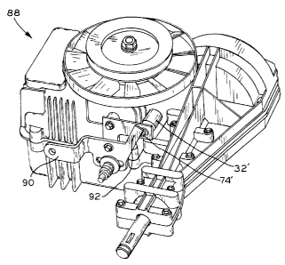
[0038) Fi~Tures 8 and 9 show hydrostatic transmission 88 having a shift
mechanism
in which shift lever 90 moves a swash plate (not shown) or a track rind (not
shown) to
vary the hydrostatic pump displacement and the direction of fluid flow between
the
pump and the motor of the transmission. Shift lever 90 is inte;rally formed
with flat
metal piece or portion 92 which abuts plunger ?=1' of solenoid ~2' when
plunger 74' is in
its extended position and the shift mechanism is moved toward its reverse
position.
The abutment of portion 92 with extended plunger 74' prevents hydrostatic
transmission 88 from being shifted from neutral into reverse. In Figure 9,
plunger 74'
of solenoid 32' is in its retracted position and portion 92 is able to move
past retracted
plunger ?4' and into any one of its variable reverse positions.
[0039] Figure 10 shows the schematic wiring diagram for activating solenoid
~2,
32'. As shown, the electrical system of mower 20 includes ground 94, battery
96,
starter 98, ignition switch 100, ignition unit 108, alternator 126, headlights
128, and
fuse 110. The electrical system also includes solenoid 104, which may be used
for
other operations associated with mower 20, clutch/brake switch 102, and seat
switch
106. Clutch/brake switch 102 is shown in the position which represents the
pedal being
up, and seat switch 106 is shown in the position representing that the seat
not being
occupied by the operator of mower 20. Switch 112 is connected to clutch/brake
switch
102 by terminals 114, 122, and 120. Switch 112 is connected to ignition switch
100 at
terminal 118 and is connected to the seat switch 106 at terminal 120. Terminal
116 is
connected to solenoid 104 and terminal 124 is connected to solenoid 32, 32'
for
actuation of plunger 74, 74'; each of the solenoids 104 and 32. 32' is further
connected
to ground 94.
(00:0] As shown in Figure 10, the switch portions between terminals 1 I 8 and
120
and between terminals 122 and 124 are open when the clutch pedal is up, as
indicated
FW'I\1,1N1',I"?91: I DOC: 1 1
CA 02405134 2002-09-25
by the position of clutch~'bral:e switch 10?, thereby breaking anv electrical
connection.
while the switch portion between terminals 114 and 116 is closed. again when
the
clutch pedal is up, to provide electrical connection between clutc?L'brake
switch 10?
and solenoid 10=t.
[0041] In operation. when the operator starts mower deck ?8 after engine
ignition.
the reverse switch 11? is closed between terminals 122 and 124 since clutch
pedal is
depressed to engage mower deck 28, such that current is applied to solenoid 32
and its
windings are energized. Plunger 74 is biased into its retracted position, and
through
energizing the windings of solenoid 32, plunger 74 is extended, thereby
preventing the
operator from moving mower 20 into reverse. When mower deck 28 is not
operating,
or when the clutch pedal is up, the connection between terminals 122 and 124
is
opened, and thus no current is applied to solenoid 32, the windings of the
solenoid 32
are not energized, and plunger 74 is not extended. Unless the clutch pedal is
depressed,
or the mower deck is engaged, plunger 74 assumes its retracted position and
mower 20
may be shifted into reverse by the operator.
(0042] While this invention has been described as having exemplary structures,
the
present invention can be further modified within the spirit and scope of this
disclosure.
This application is therefore intended to cover any variations, uses, or
adaptations of
the invention using its general principles. Further, this application is
intended to cover
such departures from the present disclosure as come within known or customary
practice in the art to which this invention pertains and which fall within the
limits of the
appended claims.
F\~'IVi,\v1.1'9SIp I DUC 17