Note: Descriptions are shown in the official language in which they were submitted.
CA 02405189 2002-10-04
WO 01/78243 PCT/ILO1/00293
RADIATION-FREE CELLULAR TELEPHONE SYSTEM
BACKGROUND OF THE INVENTION
1. Field of the invention
The present invention relates to cellular telephones and, more particularly,
to a
system for using a cellular telephone without producing potentially hazardous
radiation
near the body of users.
2. Description of the prior art
Cellular phones are becoming omnipresent and necessary elements as society
enters
the new millennium. Unfortunately, operating on radio frequency transmission,
these are
also sources of electromagnetic radiation. Most phones include an antenna that
is placed
close to the user's head, emitted radiation and suspected to be hazardous to
users.
Attempts to reduce the emitted radiation by placing a shield around the
antenna, have
been found to be impractical and thus have not been commonly employed in
cellular
telephones. Another proposed solution is to avoid placing the antenna near the
head of the
user. Proposed and now commonly available is an electrical wire that is
connected to the
telephone at the input/output port of the cellular phone and terminating with
an earpiece
that is placed in the user's ear. A microphone is mounted on the wire near the
earpiece,
putting it at the level of the mouth of the user when the earpiece is placed
in the ear. In
such an arrangement, the telephone may be clipped to a user's belt or placed
in a pocket
or a purse, with the wire extending therefrom. The earpiece is placed in the
user's ear.
When the user receives or makes a telephone call, the user merely activates
the "send" or
similar button on the cellular telephone to complete the call hands free. The
user hears
through the earpiece, the other party hearing the user through the signal
picked up by the
microphone which is in proximity of the mouth. Another configuration of
cellular
telephones in use includes a loudspeaker coupled directly to and mounted on a
cellular
telephone. The user can hear the emitted sounds with no need to hold the
cellular
telephone close to head. However, since a loudspeaker is used instead of a
microphone,
CA 02405189 2002-10-04
WO 01/78243 PCT/ILO1/00293
privacy is denied unless the user is alone.
Not only do these solutions provide for hands free operation of the telephone,
they
were also believed to have resolved the problem of unwanted radiation near the
user's
head, the telephone being remote therefrom. Unfortunately, recent studies
conducted in
Britain in 2000 have shown that such a wire configuration does not reduce
radiation near
the user's head.
There have been number of attempts aimed at solving the problem of potentially
hazardous radiation emitted from cellular telephones.
U.S. Pat. No. 4.090,042 relates to acoustical communications headset including
tubes for the transmission of sound.
U.S. Pat. No. 5,528,689 relates to a method for converting a cellular
telephone into
a headset telephone. U-shaped clips are used for attaching a mouth cup and an
ear cup to
the cellular telephone. However, there is still a problem that might evolve
from
disposition of these cups. Such disposition will interfere significantly with
the smooth
operation of the cellular telephone, since too much noise from the
surroundings might be
picked up by the microphone, or alternatively mask the sound coming from the
earpiece.
In addition, headset adjustment to user's head is done by a complicated
mechanism that
may easily dismembered.
U.S Pat. No. 5,613,222 relates to a hands-free cellular phone that employ
acoustical
tubes. A receiving cup is attached to the speaker of the cellular telephone by
loop type
Velcro fasteners. However. Velcro straps can still be bulky and accidentally
detached.
Such disposition will interfere significantly with smooth operation of the
cellular
telephone, since too much ambient noise from surrounding might be picked up by
the
microphone.
While these devices fulfill their particular objectives and requirements the
aforementioned devices are not effective when the telephone has to be located
more than
ten feet away from the user, since longer acoustical tubes absorbs too much
noise from
surroundings.
In addition, receiving and transmitting of sound waves between the cellular
phone
and the user is not mediated by any apparatus capable of amplifying, coding,
decoding,
2
CA 02405189 2002-10-04
WO 01/78243 PCT/ILO1/00293
filtering, or conferring any other change on the sounds heard or spoken. Such
apparatus.
hereafter called a conversion device, is required especially when using the
cellular phone
near a source of loud noise. There is therefore a need for producing a
cellular telephone
employing acoustical tubing that can be employed in a noisy environment.
SUMMARY OF THE INVENTION:
The present invention relates to cellular phone systems which use acoustical
tubes
for the transmission of sound. The present invention successfully addresses
the
shortcomings of the prior art by transmitting sound signals between the
telephone and
earpiece or microphone via a combination of electrical wire and acoustical
tube
connected end to end by a novel conversion device.
This conversion device may be connected to any kind of electrical output of
mobile
telephones and other apparatus. Hence, there is no need to make any changes in
the
configuration of existing mobile telephone in order to use this system.
In these respects, the present invention substantially departs from the
conventional
concepts and designs of the prior art, and in so doing provides an apparatus
primarily
developed for the purpose of communicating near loud noise sources.
BRIEF DESCRIPTION OF THE DRAWINGS:
The invention is herein described, by way of example only, with reference to
the
accompanying drawings. With specific reference now to the drawings in detail,
it is
stressed that the particulars shown are by way of example and for purposes of
illustrative
discussion of the preferred embodiments of the present invention only, and are
presented
in the cause of providing what is believed to be the most useful and readily
understood
description of the principles and conceptual aspects of the invention. In this
regard, no
attempt is made to show structural details of the invention in more detail
than is necessary
for a fundamental understanding of the invention, the description taken with
the drawings
making apparent to those skilled in the art how the several forms of the
invention may be
embodied in practice.
3
CA 02405189 2002-10-04
WO 01/78243 PCT/ILO1/00293
In the drawings:
FTG. 1 shows a prior art cellular telephone coupled to an earpiece and a
microphone
via an electrical wire;
FIG. 2 shows a cellular telephone system in which a telephone is coupled to
acoustical
tube. The acoustical tube is coupled to a conversion device, which is coupled
to the
cellular telephone via electrical wire. The acoustical earpiece is coupled to
the acoustical
tube. The electric microphone is coupled to the cellular telephone by an
electric wire;
FIG. 3 shows a cellular telephone system in which a telephone is coupled to
acoustical
tube. The acoustical tube is coupled to a conversion device, which is coupled
to the
cellular telephone via electrical wire;
FIG. 4 shows a cellular telephone system in which a telephone is coupled
without
wires to acoustical tube. The acoustical tube is coupled to a first conversion
device. A
second conversion device is coupled to the cellular telephone via electrical
wire. The two
conversion devices exchange electromagnetic signals;
FIG. 5 shows a configuration of cellular telephone system having two
conversion
devices, one on each side of an acoustical tube The two conversion devices
exchange
signals of mechanical waves;
FIG. 6 shows a cellular telephone system in which a telephone is coupled to
two
acoustical tubes. Two acoustical tubes are coupled to a conversion device,
which is
coupled to the cellular telephone via electrical wire;
FIG. 7 shows a cellular telephone system in which a telephone is coupled to
two
acoustical tubes. The acoustical tubes are coupled to a first conversion
device, which is
coupled to the cellular telephone via electrical wire. One tube is coupled to
a second
conversion device, which is coupled to an electrical microphone by an
electrical wire. A
second tube is coupled to an earpiece;
FIG. 8 is a cross sectional view of two acoustical tubes fused alongside;
FIG. 9 is a cross sectional view of two acoustical tubes fused alongside and
separated
by a web;
FIG. 10 is a cross sectional view of two concentric acoustical tubes with fins
between
their walls;
a
CA 02405189 2002-10-04
WO 01/78243 PCT/ILO1/00293
FIG. 11 is a diagram of a conversion device including a full-wave rectifier;
FIG. 12 is a diagram of a conversion device including a half wave rectifier;
FIG. 13 is a diagram of a conversion device including an amplifier connected
to the
earpiece and another amplifier connected to the microphone. A power supply is
connected to both amplifiers;
FIG. 14 is a diagram of a power supplier circuit coupled to a charger.
FIG. 15 is a diagram of a conversion device including one amplifier connected
to the
earpiece and one amplifier connected to the microphone. Power to the
amplifiers is
supplied from the mobile telephone;
FIG. 16 is a diagram of a power supply system including two power supplies and
a
charger.
DETAILED DESCRIPTION OF THE INVENTION:
For purposes of better understanding of the present invention, as illustrated
in the
drawings, reference is first made to the construction and operation of a
conventional prior
art cell phone as illustrated in FIG. 1. Such a conventional cell phone 6 may
be connected
to a microphone 2 and an earpiece 3 via an electrical wire 8. Such wire, like
the antenna
~, is a source of electromagnetic radiation which present potential health
hazards to the
user.
The principles and operation of a system according to the present invention
may be
better understood with reference to the drawings and accompanying
descriptions.
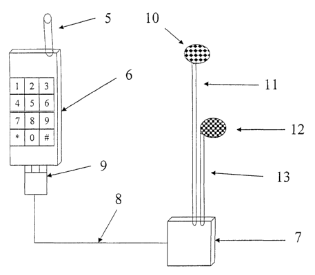
As shown in FIG. 2, a cellular telephone 6 may be connected to conversion
device 7
via an electrical wire 8 and electrical coupler 9. Conversion device 7
converts electrical
signals into sound waves that in turn are transmitted to an acoustical
earpiece 10 via an
acoustical tube 11. Electrical microphone is coupled to cellular telephone 6
via an
electrical wire 8 and and electrical coupler 9.
Referring is now made to FIG. 3, a cellular telephone 6 is connected to
conversion
device 7 via an electrical wire 8 and electrical coupler 9. Conversion device
7 converts
electrical signals into sound waves that in turn are transmitted to an
acoustical earpiece 10
via an acoustical tube 11. Speech is transmitted from an acoustical microphone
12 to the
CA 02405189 2002-10-04
WO 01/78243 PCT/ILO1/00293
conversion device 7.
Referring is now made to FIG. 4. A cellular telephone 6 is connected to a
proximal
conversion device 14 via an electrical wire and electrical coupler 9.
Conversion device 7
converts electrical signals into sound waves that in turn are transmitted to
an acoustical
earpiece 10 via an acoustical tube 11. Speech is transmitted from an
acoustical
microphone 12 to the conversion device 7. Conversion devices 7 and Referring
is now
made to FIG. 3. A cellular telephone 6 is connected to conversion device 7 via
an
electrical wire 8 and electrical coupler 9. Conversion device 7 converts
electrical signals
into sound waves that in turn are transmitted to an acoustical earpiece 10 via
an acoustical
tube 11. Speech is transmitted from an acoustical microphone 12 to the
conversion device
7.
In an alternative embodiment, the cellular telephone system of the present
invention
may contain two conversion devices as illustrated in FIG. 5. In such a case.
the telephone
6 is connected to a proximal conversion device 7 via an electrical wire 8.
Conversion
device 7 is connected to a distal conversion device 16 with an acoustical tube
11. Distal
conversion device 16 is connected to electrical earpiece 3 and electrical
microphone 2
with electrical wires 15 and 17. Proximal conversion device 7 may be connected
directly
to telephone 6 or may be an integral part of telephone 6.
Referring now to acoustical tube 11, it is made of (electrically) non-
conducting,
optionally flexible, material such as polyethylene, polypropylene,
polvvinylchloride
(PVC), etc., filled with a medium capable of conducting sound waves, such as
plasma,
gas, liquid, or solid. Instead of one tube, two tubes can be employed, one for
receiving
sound and another for transmission. Tubes may be separated by a web or fused
with one
another, wrapped together side by side or one inside the other as concentric
tubes.
Branching may appear at any position along a tube. A tube with multiple
branching
tubes may be used as an announcement system for internal communication among
the
crew of a vehicle, an airplane, a vessel or any other need of internal
communication.
The cross-section of tube 11 may be round, square or of any other geometry.
One or
more acoustical fittings such as quarter wavelength plate, a membrane or a
funnel may be
6
CA 02405189 2002-10-04
WO 01/78243 PCT/ILO1/00293
installed or embedded in a tube.
Conversion devices 7 and 16 are an essential part of the invention. They
contain at
least one transducer, which is a device capable of converting electrical
signals into sound
waves and/or vice versa. Conversion devices 14 and 20 contain a transceiver
for
exchanging electromagnetic signals. In addition, conversion devices 7, 14. 16,
and 20
may contain any of the following:
~ An encryption device.
~ A decoder.
~ An amplifier circuit.
~ A filter circuit.
~ An internal power supplier. redundantly operated.
~ A micro controller.
~ A wireless transmitter/receiver.
~ A device for sending a signal to any entrance or any exit of the conversion
device.
~ A device for changing a signal to any entrance or any exit of the
conversion device.
~ A device that can control transmission of any signal to any entrance or any
exit of the conversion device.
Some examples for possible configurations of conversion devices are shown in
FIG's 11, 12, 13 and 15.
In a specifically preferred embodiment shown in FIG. 11, the invention is
related to
a conversion device 7 including a full-wave rectifier 54 with an amplifier 52
connected to
the speaker 50, and an acoustical tube 11 for the microphone 51 and the
speaker 50.
In another embodiment shown in FIG. 12, the invention is related to conversion
device 7 including a half wave rectifier 55 with an amplifier 52 in the path
of speaker 50,
and acoustical tubes 11 for the microphone 51 and the speaker 50.
Further, the invention is related to a conversion device 7 as shown in FIG.
13.
Conversion device 7 comprises one amplifier 52 connected to earpiece 50, and
one
amplifier 53 connected to microphone 51, with separate acoustical tubes 11 for
the
CA 02405189 2002-10-04
WO 01/78243 PCT/ILO1/00293
microphone 51 and the earpiece 50. A power supplier 56 is connected to
amplifiers 52
and 53. A momentary switch 74 may be installed for the purpose of controlling
microphone 51. A switch 75 may be installed for the purpose of controlling the
conversion device from the cellular telephone.
As shown in FIG. 14, a removable charger 58 may be installed, for charging of
the
power supplier 57. A switch 76 is used for coupling the amplifier 52 to the
power
supplier 57.
Still Further, the invention is related to a conversion device 7 as shown in
FIG. 15.
Conversion device 7 comprises a first amplifier 52 in the path of earpiece 50,
and one
amplifier 53 in the path of the microphone 51, with separate acoustical tubes
11 for a
microphone 51 and an earpiece 50. Power to the amplifiers is supplied from the
mobile
telephone via electrical wires 60 and 61.
An example of a power supply system that can be utilized in the construction
of
conversion devices is shown in FIG. 16. The system comprises two power
suppliers 56,
57 and a charger 58 controlled by a micro switch 62. The micro switch 62
selects the
suitable power supplier for the amplifier 52 of the conversion device.
The use of an amplifier improves the transmission of sound waves and
especially
required for the transmission of sound wave to long distances.
The internal power supplier may be a battery, a solar cell, a wind vane, an
apparatus
for coupling kinetic energy to conversion device, or any other energy source.
The power
supplier may be connected to an amplifier.
~ Typical amplifiers are described in the following publications:
Ralph J. Smith, Circuits, Devices and Systems, second edition (1971), pp.
365, fig. 11.21 and pp. 376, fig. 11.31(a)
305 Circuits, Elcktor Elecktronice publishing (1995), ISBN 090570536x, pp.
19, fig. 924053-11.
~ Typical microphone amplifier circuit configurations are described in:
305 Circuits, Elcktor Elecktronice publishing, ISBN 090570536x, pp. 33, fig.
934039-11.
s
CA 02405189 2002-10-04
WO 01/78243 PCT/ILO1/00293
~ Typical filter circuit configurations are described in:
Ralph J. Smith, Circuits, Devices and Systems, second edition (1971), pp.
404, figs. 12.15(a), and 12.16(a).
305 Circuits, Elcktor Elecktronice publishing, ISBN 090570536x, pp. 31, fig.
924095-11.
~ Typical wave rectifier circuit configurations are described in:
Ralph J. Smith, Circuits, Devices and Systems, second edition (1971), pp.
393, fig. 12.3(a).
305 Circuits, Elcktor Elecktronice publishing, ISBN 090570536x, pp. 14, fig.
914122-11; page 137, fig. 934024-11.
~ Typical relay circuit configurations are described in:
305 Circuits, Elcktor Elecktronice publishing, ISBN 090570536x, pp. 14, fig.
914122-11.
~ Typical charger circuit configurations are described in:
305 Circuits, Elcktor Elecktronice publishing, ISBN 090570536x, pp. 96, fig.
914004-1 l; pp. 103, fig. 914047-11.
An electrical microphone is defined as a device for the conversion of sound
waves
into an electrical signal. An electrical earpiece is defined as a device for
the conversion of
an electrical signal into sound waves.
Acoustical microphone and earpiece may optionally be unified in one device.
An electrical coupler is a device at one end of a wire or a conversion device
with
which it is attached to an input/output port of a cellular telephone.
Instead of a telephone, there may be a cell phone, a wireless
transmitter/receiver,
a computer, a CD player, a tape recorder, a DVD, a video camera or any other
means of
communication. When data is transmitted, electrical signals are converted into
sound
waves and vice versa.
In addition, the transmission of sound waves is insensitive to surrounding
electromagnetic field.
9
CA 02405189 2002-10-04
WO 01/78243 PCT/ILO1/00293
Additional objects, advantages, and novel features of the present invention
will
become apparent to one ordinarily skilled in the art upon examination of the
figures,
which are not intended to be limiting.
l0