Note: Descriptions are shown in the official language in which they were submitted.
CA 02405322 2002-09-26
CHANNEL CODE DECODING FOR THE CDMA FORWARD LINK
CROSS-REFERENCE TO RELATED APPLICATIONS
This invention claims priority from United States provisional application no.
60/325,183 filed September 28, 2001.
BACKGROUND OF THE INVENTION
Ol This invention relates to the forward link of a CDMA cellular telephone
network
as shown in Fig 1. Blocks I01, 102 and 103 are data sources representing the
information
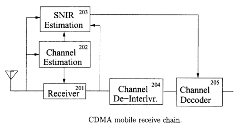
transmitted to each mobile communicating with the base station. Blocks 104,
105 and
106 are the channel coders that add structured redundancy to the information
streams.
This coding is used for error correction in the mobile. Channel interleaving
is added in
blocks 107, 108 and 109 to shuffle the order of the encoded symbols. This
improves
channel code performance in the presence of burst errors. The signals are then
each
spread with unique spreading codes generated in blocks 110, 111 and 112, added
together
and spread with a common spreading code generated in block 113. Orthogonal
Walsh
codes are commonly used in blocks 110, 111 and 112 and a PN sequence-based
code is
commonly used in block 113.
02 For conventional base station operation, block 114 performs the modulation
and
analog signal processing necessary to transmit the forward channel signal
using a single
antenna. If transmit diversity is being used, block 114 performs the
processing necessary
to transmit the forward channel signal using two or more antennas.
03 The composite forward channel signal travels through the radio channel in
block
115. The mobile receiver in block 116 extracts the signal through a
despreading process
and optionally performs some processing on the different multipath replicas of
the
received signal. This processing can be used to increase the energy of the
desired signal
or to cancel interference from the other signals transmitted by the base
station. Block 117
de-interleaves the samples of the received signal. The channel decoder in
block 118 uses
CA 02405322 2002-09-26
2
the channel coding added to the information stream to perform error correction
and
produce an estimate of the transmitted information.
04 On the CDMA forward link, the amplitude of the desired signal and the level
of
the interference corrupting that signal will change with time. This makes some
channel
encoded symbols at the mobile receiver output more reliable than others.
Convolutional
and turbo codes are typically used for error correction on the CDMA forward
link [2, 3,
4]. The channel decoder algorithms for these codes are all improved if they
are provided
with reliability estimates for each received symbol [5, 6].
OS This reliability information is typically an estimate of the received
energy of an
encoded symbol divided by an estimate of the variance of the interference plus
noise
corrupting that symbol. This signal to interference plus noise ratio (SNIR)
for received
symbol i is denoted 'y; and must be calculated at the input to channel decoder
block 118.
This is equivalent to calculating y; at the output of receiver block 116 since
the de-
interleaver block 117 does not alter y;.
SUMMARY OF THE INVENTION
06 This patent improves error correction performance using a new technique for
calculating more accurate estimates of y; at the output of receiver block 116.
The
accuracy of the estimates is improved by separately calculating the variance
of the in-cell
interference and out-of cell interference plus thermal noise processes at the
output of
receiver block 116. For this purpose, the receiver chain of Fig. 1 is modified
to include a
SNIR estimator, where the SNIR estimator separately estimates the variance of
the in-cell
interference and the out-of cell interference plus noise. In addition, this
patent provides a
technique for determining the variance of in-cell interference and out-of cell
interference
plus thermal noise at the input to receiver block 116. This information is
required by the
SNIR estimator block.
CA 02405322 2002-09-26
3
07 U.S. patent 5,903,554 also estimates SNIR by separately considering in-cell
and
out-of cell interference. However, this patent uses its SNIR estimates for
generating
forward link power control commands rather than improving channel decoding. As
well,
U.S. patent 5,903,554 calculates the level of in-cell interference by
multiplying the level
of the pilot signal by a coefficient. This coefficient is either calculated by
the mobile or
transmitted from the base station. The technique presented in this disclosure
determines
in-cell interference variance based on interference levels at the receiver
input, radio
channel conditions, the spreading codes used on the CDMA forward link and the
multipath combining performed by the mobile receiver.
BRIEF DESCRIPTION OF THE DRAWINGS
08 There will now be described preferred embodiments of the invention, with
respect
to the drawings, by way of illustration only, in which:
Fig. 1 is a schematic showing a prior art CDMA forward link;
Fig. 2 is a schematic showing elements of a mobile receive chain according to
an
embodiment of the invention;
Fig. 3 is a schematic showing a receiver for use in the embodiment of the
invention shown in Fig. 2; and
Fig. 4is a schematic showing a second receiver for use in the embodiment of
the
invention shown in Fig. 2.
DESCRIPTION OF PREFERRED EMBODIMENTS
09 The signal to interference plus noise ratio at the output of receiver block
116
during encoded symbol interval i can be written as y; = E, ~az (i) where E; is
the energy
of the received encoded symbol and a2 (i) is the variance of the interference
and noise
corrupting that symbol. An estimate of E; is calculated using conventional
techniques
described below. This invention improves the accuracy of y; through a new
technique for
calculating a2 (i) that separately accounts for the in-cell interference and
out-of cell
interference plus thermal noise levels on the CDMA forward link.
CA 02405322 2002-09-26
4
The desired signal received by a CDMA mobile is corrupted by three processes:
in-cell interference, out-of cell interference and thermal noise. In-cell
interference is
corruption from the other signals transmitted by the base station or base
stations
communicating with the mobile. In soft or softer handoff, all the base
stations
participating in the handoff produce in-cell interference. Out-of cell
interference is
corruption from the signals transmitted by the base stations that are not
communicating
with the mobile and is typically lumped together with thermal channel noise.
During
symbol interval i , the in-cell interference at the output of receiver block
116 is denoted
I; and the out-of cell interference plus thermal noise component at the output
of receiver
block 116 is denoted N; .
11 Fig. 2 shows a block diagram of a CDMA mobile receive chain that
incorporates
an embodiment of this invention. Block 201 is the receiver block that extracts
the channel
encoded data stream transmitted by the base station and may for example be a
Rake
receiver. Any of various receivers may be used to perform multipath processing
on the
received signal. This invention is described specifically in relation to a
Rake receiver,
but is not limited to a Rake receiver for all embodiments. Block 204 de-
interleaves the
received encoded symbols and black 205 performs error correction using the
forward link
channel code. Using techniques well known in the art, the channel estimation
block 202
determines the complex impulse response of the forward link radio channel
using the
pilot signal transmitted by the base station.
12 According to an embodiment of this invention there is proposed the addition
of
block 203 for calculating estimates of y; based on the signal at the input to
receiver block
201, the signal at the output of receiver block 201 and the channel impulse
response
information calculated by block 202. Block 203 calculates y; according to
E' ~l)
Y. = ~Iz~+~N?~
CA 02405322 2002-09-26
where (I,2 ) and (N;2 ) denote the variance of the in-cell interference and
out-of cell
interference plus thermal noise processes at the output of receiver block 201.
The
following describes the procedure used by block 203 to calculate E; , (l; )
and (N,? ) for
single antenna base station transmission and transmit diversity.
SINGLE ANTENNA BASE STATION TRANSMISSION
13 Let X; (n) be the spread spectrum waveform used by a CDMA base station to
transmit the ith channel encoded symbol x; to user 0 in a sector with K users.
The
waveform is expressed in discrete time at two samples per spreading code chip
as
X; (n) = G; x; a0 (n - 2iR) where R is the number of spreading code chips per
encoded data
symbol, G; is the forward link power control gain factor applied to x; and ak
(n) is the
complex spreading code waveform assigned to user k. In the following, the
encoded data
symbols are assumed to be real valued such that x; E {-1,1} . However, this
technique can
be extended to complex valued symbols in a straightforward manner. The
spreading code,
ak (n) , is commonly the product of a real valued Walsh code unique for each
user,
generated in blocks 110, 111 or 112, and a complex valued PN spreading
sequence that is
common for all users in the sector, generated in block 113
14 The complex valued samples of the forward channel impulse response are
written
as c(n, l ), l = 0, . . . L -1, where l signifies excess delay in half chip
intervals. This
response represents the multipath reflections between the mobile and all the
base stations
communicating with the mobile. The number of impulse response samples with
significant signal energy at time n is equal to L.
The channel estimation block 202 determines the discrete time complex impulse
response of the forward radio channel for each symbol interval l. It is
assumed that the
channel remains constant for the symbol interval such that the estimate of
c(2iR, Tj
produced by block 202 remains valid fox the entire symbol duration. In the
following, the
term c(r7 will be used to refer to c(2iR, ~, where the index 2iR is removed
for brevity.
CA 02405322 2002-09-26
6
16 Fig. 3 illustrates a detailed example of the receiver structure in block
201 that can
be used for single antenna base station transmission. Blocks 301, 302 and 303
are three of
the W parallel branches for processing the different multipath replicas of the
forward
channel signal. The signal components tracked by the receiver branches are
located at
channel delays zo , z, , . . . zW_, , where 0 <_ z W <_ L -1. Each branch
extracts the desired
signal using a despreading operation. After despreading, the branch outputs
are aligned in
time, multiplied by combining weights and added together. The combining
weights are
denoted uo,u,,...uw_,.
17 Block 203 estimates E; at the output of the mobile receiver using
techniques well
know in the art. These techniques include averaging the energy of the signal
at the output
of receiver block 201.
18 Out-of cell interference and thermal noise is typically modeled as a single
Gaussian process at the receiver input [7, 8, 9]. Accounting for the multipath
combining
and despreading performed within the receiver, the out-of cell interference
plus thermal
noise affecting symbol x; at the receiver output is
N _ ~w_~ a
,~=o w
y'~ ~; iv ao (2r)N(2iR + z,~ + 2r) (2)
- ~w-~ a N
w=o w w,i
where N(n) denotes the out-of cell interference plus thermal noise process at
the input to
the receiver in discrete time at two samples per chip resolution. Two samples
per chip is
two times oversampling of the received signal. Therefore, N(n) is a coloured
complex
Gaussian process with zero mean and variance 6 N that becomes white when
decimated
to one sample per chip.
19 The despreading stage in each receiver branch does not alter the Gaussian
distribution of the out-of cell interference. Samples of a Gaussian process
that are
multiplied by a pseudorandom spreading code with real and imaginary components
equal
CA 02405322 2002-09-26
7
to 1 or -1 retain a Gaussian distribution. The Gaussian process at the output
of the
normalized despreading summation block in Fig. 3 has the same variance as the
Gaussian
process at the input to the summation [ 1 ]. Therefore, N",,; in (2) is a
complex white
Gaussian process with zero mean and variance aN . Due to the independence of
Nw,; , w = 0, . . . W -1, the SNIR estimation algorithm implemented in block
203 calculates
the variance of N, according to
w-i
~N~~)=aN~~uw ~z. (3)
w=o
where the technique for determining aN is also implemented in block 203 and is
discussed below.
20 After undergoing path-loss and shadowing effects, the composite forward
link
signal transmitted by the base station is represented in discrete time at two
samples per
chip as I(n). Assuming a large number of users, this signal is modeled as a
coloured
complex Gaussian process with zero mean and variance s; that becomes white
when
decimated to one sample per chip. Since I(n) propagates through the forward
link radio
channel, the in-cell interference at the output of finger w can be written as
_ r n-i
Iw,~ - uw fR fro~ ao(2r)
~_o c(l)1(2iR + z~~, -l + 2r)
21 Receiver branch w will extract the desired signal from the component of
I(n)
arriving at delay z",. Assuming orthogonal Walsh codes are used for forward
link
spreading, the despreading performed by receiver branch w will completely
cancel the
signals of the K - 1 interfering users that also arrive at delay z",.
Therefore,
Iw,~ - uw ~e(l)I ~".-~,;
,_
l*z".
where the term I,,; is the normalized sum of R samples of the Gaussian process
I(n)
multiplied by the spreading code of user 0 with an offset of r during symbol
interval i. As
was the case for out-of cell interference, the despreading operation in (4)
does not alter
CA 02405322 2002-09-26
g
the Gaussian distribution of I(n). Therefore, I,.,; is a complex white
Gaussian random
process with zero mean and variance a; .
22 Let the vector I; =[lo,,,...lw._,,;]'represent the in-cell interference at
the finger
outputs during symbol interval i. The covariance matrix R = E{I;IH }
represents the
second order statistics of the interference where the elements of the matrix
are
'Ymn = al 'h0 4y=o umC(~)(UnC(~))*
' S((9 - l ) - (n - m)) (6)
' [1- b(m -l))[1-b(n - R'))
where the technique for determining a; is also implemented in block 203 and is
discussed below.
The total in-cell interference at the mobile receiver output is I; _ ~w=o
1~",; . Using (6), the
variance of l; is calculated in block 203 according to
W-1 W-I
~I~Z~ ~ ~~mn ' 7
m=0 n=0
TIME DELAY TRANSMIT DIVERSITY (TDTD)
23 When using TDTD, the base station transmits the same CDMA signal from two
antennas with the second antenna delayed by Ld channel delay samples, where Ld
>= L
[10). This artificially increases the number of multipath reflections which
can improve
the diversity achieved when the mobile receiver processes the different
multipath
components of the forward channel signal. The mobile receiver chain in Fig. 2
and the
technique for calculating y; used for single antenna base station transmission
can be
applied without change to the signal received from a base station using TDTD.
PHASE SWEEP TRANSMIT DIVERSITY (PSTD)
CA 02405322 2002-09-26
9
24 When using PSTD, the base station transmits the same signal from two
antennas
using slightly offset carrier frequencies. The signals combine in the radio
channel to
produce artificially fast fading, improving interleaver performance for low
velocity
mobiles [10]. The mobile receiver chain in Fig. 2 and the technique for
calculating y;
used for single antenna base station transmission can be applied without
change to the
signal received from a base station using PSTD.
SPACE TIME TRANSMIT DIVERSITY (STTD)
25 Space Time Transmit Diversity (STTD) is a technique first proposed by
Alamouti
[11] that has been adapted for use in CDMA systems. The encoded data symbols
are
transmitted in such a way that the fingers of a mobile Rake receiver are able
to perform
maximal ratio combining on the signals received from the base station
antennas.
26 For user 0, the discrete time signals transmitted by the base station at
two samples
per chip are
X ° (n) = G, x; ao (n - 2iR)
X' (n) - Ga x +~ ao (n - 2iR), i even (8)
- G; x,' , ap (n - 2iR), i odd
where X a (n) is the signal transmitted from antenna a during symbol interval
i.
27 The CDMA mobile receive chain for single antenna base station transmission
in
Fig. 2 is also used by mobiles receiving an STTD signal. However, receiver
block 201
requires modification that is shown in detail in Fig. 4. Blocks 401, 402 and
403 are three
of the W parallel branches used by the receiver for processing the different
multipath
components of the signal received from the base station. The contents of block
401 are
shown in detail to illustrate the processing performed on one multipath
component of the
received base station signal. It is assumed that the channel remains
stationary over two
encoded symbol intervals. The term ca (n, l ) refers to the complex channel
response
CA 02405322 2002-09-26
to
between base station antenna a and the mobile. In the following, the term ca
(2iR, l ) is
replaced with ca (1 ) for brevity.
28 The receiver processing described by Alamouti must be performed using the
signal received over two consecutive symbol intervals [ 11 ]. Therefore, the
output of the
despreading stage during even symbol intervals is buffered by a unit delay
element so
that the Alamouti processing can be performed during the odd symbol intervals.
The
multiplexing block places the information symbol output by the upper branch in
front of
the information symbol from the lower branch.
29 Block 203 estimates E; at the output of the mobile receiver using
techniques well
know in the art. These techniques include averaging the energy of the signal
at the output
of receiver block 201.
30 As for the single antenna case, the out-of cell interference plus thermal
noise at
the mobile receiver input is denoted N(n) and the interference at the output
of the
despreading stage is denoted NW,;. Accounting for STTD combining, the out-of
cell
interference at the Rake receiver output during symbol interval i is
N; _
~~'-' c' (z 1 N - c (z , )N* i even (g)
W=o o w w,i ~ w w,i+~
~w=o co (zW )NW,r 'F- c, (zW )NW.;-, i odd
Due to the independence of N",,, , w = 0, . . . W -1, the SNIR estimation
algorithm in block
203 estimates the variance of N; according to
w-,~
(Nr2)=a'N ~~~co(ZW)~2 +~ct(Zw~)~2~ ~ (10)
W=o
where the technique for determining QN is also implemented in block 203 and is
discussed below.
31 After undergoing path-loss and shadowing effects, the composite forward
link
signal transmitted by base station antenna a is represented in discrete time
at two samples
CA 02405322 2002-09-26
per chip as la (n) . Assuming a large number of users, the signals transmitted
by different
antennas are independent and are modeled as coloured complex Gaussian
processes with
zero mean and variance a; that become white when decimated to one sample per
chip.
32 Receiver branch w will extract the desired signal from the component of
I °' (n) arriving at delay z",. Assuming orthogonal Walsh codes are
used for forward link
spreading, the despreading performed by finger w will completely cancel the
signals of
the K - 1 interfering users that also arrive at delay zw. Therefore, the in-
cell interference at
the finger output is
IW,~ _
~ 1-« ~o(zW)~co(l)I°.-~,~ +c,(1)IZw-,.~~
1*~".
- ci (zw )~co (l )I °,....~,;+i + c~ (l )I'".-r.~+v r }~ i even ( 11 )
~ ~._~~ ~co (zw )[co (l )I ~, -r,. + c~ (l )I'" -t,~
~*:".
+ c, (zw )[co (l)1 ~, -.r,~_., + c, (l )I'" _,,;-, ~ ~, i odd
where 1"; is the normalized sum of R samples of 1 a (n) multiplied by ao (n)
with an offset
of r during symbol interval i. The overall in-cell interference at the mobile
receiver
output is given by I; _ ~w o Iw,; .
33 If I; =[lo,,,...lW-~,;]T represents the in-cell interference at the
receiver branch
outputs in Fig. 4 during symbol interval i, then the elements of the
covariance matrix
R = E{I;IH } are equal to
= a,z ~t_ 1 ~J.-1
~mn / !-0 q=0
[co (zm )co (l )~o (~r, )~'0 (9) + ca (znt )c. (l )~0 (z" )~l (f ) ( 12)
+ C~ (Zm )CO (I )C~ (Zn )CO (CJ) + C~ (Zm )C~ (I )C~ (Zn )C~ (C~')]
b((9 - ~) - (r2 -- m))[1- S(m - l)] [l - S(n - f )]
where the technique for determining a; is also implemented in block 203 and is
discussed below.
CA 02405322 2002-09-26
is
34 Using these covariance matrix elements, the variance of l; is calculated by
block
203 according to
W-I W-1
(la) _ ~ ~ ~Pmn (13)
m=0 n=0
ESTIMATION OF INPUT INTERFERENCE LEVELS
35 This disclosure shows that the quantities 6; and aN are required to
determine in-
cell interference and out-of cell interference plus thermal noise levels at
the output of
mobile receiver block 201. These quantities must be estimated from the signal
at the
input to block 201. The term a; is the variance of the forward channel signal
received
from all the base stations communicating with the mobile after path loss and
shadowing
but before small scale multipath channel effects. Alternatively, the quantity
a; can be
interpretted as the power of the signal received by the mobile from the base
stations it
communicates with after small scale channel effects are averaged out. The
quantity aN
is the variance of the out-of cell interference plus thermal noise process at
the input to
mobile receiver block 201.
36 The algorithm in block 203 determines a; and a~N using the second order
statistics of the signal at the input to receiver block 201. The discrete time
signal at the
input to block 201 is denoted at one sample per chip as y(k) = c~, (k, g) *
I~, (k) + N~, (k) ,
where * indicates convolution. The terms Id(k) and Nd(k) are I(n) and N(n)
decimated to
one sample per chip, respectively. The term cd(k,q) is c(n,l) decimated to one
sample per
chip in both time and excess delay.
37 The autocorrelation function of y(k), r" _ ( y(k)y' (k - u)) will be a
function of
cd (k, q) , a; , and 6N for v = 0. However, since Na(k) is white, r,, will be
a function only
of cd (k, q) and a; for v ~ 0. This observation can be used to determine a;
and aN from
samples of the interference and noise waveform, y(k), at the mobile receiver
input.
CA 02405322 2002-09-26
13
38 Since cd(k,q) is determined by block 202, the channel terms can be treated
as
constants rather than random processes when calculating r~, . The
autocorrelation function
of y(k) can therefore be written as
r~ -
~~o~m=ocd(k~i)cd(k "v~m)(Id(k-i)Id(k-m-v))
+ ~Nd (k)Na (k - v)), v <_ L
0, otherwise
( 14)
Since the spreading code chip rate is typically much higher than the maximum
Doppler
frequency of the channel, cd (k, q) = cd (k - u, q) = cd (q) for a <_ L ,
where the notation
cd(g) is used for brevity. The expression in (14) can be simplified to
c-t t.-t
rv = a; ~ E cd (i)c; (m)~((i - m) - u) + aN 8(u) ( 15)
.=o n~=o
where d(z) equals 1 for z = 0 and 0 otherwise.
39 It is noted that (15) is a linear function of the variances being
estimated. The
autocorrelation values for 0 5 v <_ L -1 can be written as a series of linear
equations such
that
r = HO ( 16)
where r=[ro,...r~_t]T,O=[aNa;]'and
1 EL o ~,'"3ocd (i)c~r (m)8(i - m)
0 E~ o ~n~ ocd (i)cd (m)S((l - m) -1)
H = ( 17)
~~~~ ~n ~O~d (l)Cd (m)s 1 m - (L -1
The elements of r can be determined from the received signal using a time
average,
where
N~._t
r° = :'V ~ y(m)Y~ (m - u) (18)
s
CA 02405322 2002-09-26
14
40 Since (16) is a linear equation defining the unknown parameters, the Least-
Squares Estimator (LSE) can be used such that
[a~,a; ]'~ _ (HTH)-' Hr. (19)
The time interval required to collect the NS samples used in (18) is equal to
T,. = N5. ~RS. ,
where Rs is sampling rate. The calculation in (18) must be performed while the
channel is
stationary, such that T, 5 T~. , where T~ is the coherence time of the
channel. If T, > T~ ,
due to a large NS, then the TS second interval is divided into several
consecutive smaller
intervals, each shorter than T~. Estimates of a? and a ~, are calculated
during each of
these shorter intervals and then averaged together. Since the estimator is
linear, the
accuracy of this average is equivalent to the accuracy of the single estimate
possible if the
channel remained stationary for the full TS.
41 REFERENCES (all of which are hereby incorporated by reference herein where
permissible by law)
[1) J. G. Proakis, Digital Communications, McGraw Hill, 4 edition, 2001.
[2) TIA/EIA, IS-95-B: TIA1EIA Interim Standard: Mobile Station Base Station
Compatibility Standard for Dual-Mode Wideband Spread Spectrum Cellular
System, Telecommunications Industry Association, 1995.
[3] TIA/EIA, IS-2000-2: TIA~EIA Physical layer standard for cdma2000 spread
spectrum systems, Telecommunications Industry Association, 1999.
[4] 3rd Generation Partnership Project, "Technical specification group radio
access
network: Multiplexing and channel coding (FDD) (release 1999)," 2000-03,
V3.2Ø
[5] M. Rahnema and Y. Antia, \Optimum soft decision decoding with channel
state
information in the presence of fading," IEEE Communications Magazine, vol. 35,
no. 7, pp. 110-111, July 1997.
CA 02405322 2002-09-26
[6] B. Vucetic and J. Yuan, Turbo Codes: Principles and Applications, Kluwer,
2000.
[7] W. Mohr and M. Kottkamp, "Downlink performance of IS-95 DS-CDMA under
multipath propagation conditions," in IEEE Fourth International Symposium on
Spread Spectrum Techniques and Applications, September 1996, vol. 3, pp. 1063-
1067.
[8] M. R. Hueda, C. Rodriguez, and C. Marques, "New interpath interference
model for
DSCDMA indoor transmissions with distributed antennas," in Il th IEEE
International Symposium on Personal, Indoor and Mobile Radio Communications
(PIMRC 2000), September 2000, vol. 1, pp. 92-97.
[9] H. Kim, J. Koo, Y. Han, and C. Kang, "Forward link capacity based on
interference
characteristics in CDMA systems," in 52nd IEEE VTS Fall Vehicular Technology
Conference (VTC 2000 Fall), September 2000, vol. 2, pp. 592-596.
[10] J. S. Thompson, P.M. Grant, and B.Mulgrew, \Downlink transmit diversity
schemes
for CDMA networks," in IEEE ITS 50th Vehicular Technology Conference, Fall,
September 1999, vol. 3, pp. 1382-1386.
[ 11 ] S. M. Alamouti, \A simple transmit diversity technique for wireless
communications," IEEE Journal on Selected Areas in Communication, vol. 16, no.
8, pp. 1451-1458, October 1998.
42 While an example of the principle of operation of the invention has been
described, immaterial modifications may be made to the invention as described
and these
are intended to be covered by the claims.