Language selection

Search

Patent 2405441 Summary

Third-party information liability

Some of the information on this Web page has been provided by external sources. The Government of Canada is not responsible for the accuracy, reliability or currency of the information supplied by external sources. Users wishing to rely upon this information should consult directly with the source of the information. Content provided by external sources is not subject to official languages, privacy and accessibility requirements.

Claims and Abstract availability

Any discrepancies in the text and image of the Claims and Abstract are due to differing posting times. Text of the Claims and Abstract are posted:

  • At the time the application is open to public inspection;
  • At the time of issue of the patent (grant).
(12) Patent: (11) CA 2405441
(54) English Title: IMPROVED PATTY-FORMING MOLD PLATE ASSEMBLY
(54) French Title: ENSEMBLE PLAQUE DE MOULE DE FABRICATION DE BOULETTES PERFECTIONNE
Status: Deemed expired
Bibliographic Data
(51) International Patent Classification (IPC):
  • A22C 7/00 (2006.01)
  • A23P 1/00 (2006.01)
(72) Inventors :
  • LABRUNO, RONALD F. (United States of America)
(73) Owners :
  • FORMAX, INC. (United States of America)
(71) Applicants :
  • FORMAX, INC. (United States of America)
(74) Agent: NORTON ROSE FULBRIGHT CANADA LLP/S.E.N.C.R.L., S.R.L.
(74) Associate agent:
(45) Issued: 2009-07-14
(86) PCT Filing Date: 2001-04-06
(87) Open to Public Inspection: 2001-10-18
Examination requested: 2004-10-05
Availability of licence: N/A
(25) Language of filing: English

Patent Cooperation Treaty (PCT): Yes
(86) PCT Filing Number: PCT/US2001/011421
(87) International Publication Number: WO2001/076375
(85) National Entry: 2002-10-07

(30) Application Priority Data:
Application No. Country/Territory Date
09/545,804 United States of America 2000-04-08

Abstracts

English Abstract


A mold plate assembly for a patty forming apparatus includes a mold plate (24)
having patty forming cavities (24a)
and a breather plate (34) arranged facing the mold plate. A fill slot (76) is
arranged facing the mold cavities (24a), on a side opposite
the breather plate (34), to fill food product into said mold cavity (24a) when
the mold plate (24) is in a filling position. The breather
plate (34) includes first breather holes (100) at a remote position from the
inlet slot (76) to discharge air to ensure an even and uniform
filling of the food product into the cavity, and second breather holes (110)
located close to the fill slot (76) to relieve filling pressure
at that location to avoid the formation of a ridge on the finished formed food
patty.


French Abstract

L'invention concerne un ensemble plaque de moule utilisé dans un appareil de fabrication de boulettes, comprenant une plaque de moule (24) formant des cavités (24a) et une plaque d'aération (34) située face à la plaque de moule. Une fente de remplissage (76) est située face aux cavités du moule (24a), sur un côté opposé à la plaque d'aération (34), servant à remplir de produit alimentaire ladite cavité du moule (24a) lorsque la plaque du moule (24) est en position de remplissage. La plaque d'aération (34) comprend des premiers orifices d'aération (100) à un emplacement éloigné de la fente d'entrée (76) permettant d'évacuer l'air de façon à assurer un remplissage égal et uniforme du produit alimentaire dans la cavité, et des seconds orifices d'aération (110) situés près de la fente de remplissage (76) destinés à compenser la pression de remplissage à cet emplacement afin d'éviter la formation d'une saillie sur la boulette alimentaire finie.

Claims

Note: Claims are shown in the official language in which they were submitted.


THE INVENTION CLAIMED IS:


1. An improved patty forming apparatus, comprising:

a mold plate having a mold cavity through a thickness thereof said mold
plate being free of mold obstructions along a length of said cavity;

a food product delivery channel arranged on one side of the mold plate
and having a fill opening into said cavity;

a breather plate overlying said mold plate, said breather plate having a
plurality of first breather holes therethrough located remote from said fill
opening, a
plurality of second breather holes located close to said fill opening, spaced
from said
plurality of first breather holes, a region of said breather plate between
said first and
second pluralities extending about one third the length of the cavity or
greater, said
region being substantially free of breather holes, said first and second
breather holes for
expressing air during the filling of the cavity with food product.


2. The apparatus according to claim 1, wherein said first breather holes are
located within a first area adjacent a leading edge of the cavity that is
farthest from the
fill opening, the first area extending one third of the length of the cavity,
and said second
breather holes are located within a second area adjacent an opposite edge of
the cavity
that extends one third the length of the cavity.


3. The apparatus according to claim 1, wherein said mold plate is arranged to
reciprocate with respect to said delivery channel and said breather plate.


9


4. The apparatus according to claim 2, wherein said second breather
holes have an aggregated open area not more than 50% of an aggregate area of
said first
holes.


5. The apparatus according to claim 1, wherein said plurality of second
breather holes is located directly facing said opening.


6. A food patty molding apparatus, comprising:
a machine frame;

a mold plate having at least one cavity and mounted to reciprocate with
respect to said frame to position the cavity between a filling position and a
mold patty
knock out position, said cavity being free of mold obstructions along a length
of said
cavity;

a food product delivery channel mounted stationary with respect to said
frame and having an opening into said cavity when said mold plate is in said
filling
position;

a breather plate facing said mold plate and stationary with respect to said
frame,
said breather plate having a plurality of first breather holes therethrough
located remote
from said fill opening, and a plurality of second breather holes located close
to said fill
opening, spaced from said plurality of first breather holes, a region of said
breather plate
between said first and second pluralities extending at least about one third
the length of
the cavity being substantially free of breather holes, said first and second
breather holes
for expressing air during the filling of the cavity with food product.


10


7. The apparatus according to claim 6, wherein said first breather holes are
located within a first area adjacent a leading edge of the cavity that is
farthest from the
fill opening, the first area extending one third of the length of the cavity,
and said second
breather holes are located within a second area adjacent an opposite edge of
the cavity
that extends one third the length of the cavity.


8. The apparatus according to claim 7, wherein said second breather holes
have an aggregated open area not more than 50% of an aggregate area of said
first holes.

9. The apparatus according to claim 6, wherein said breather plate includes
an air channel formed on a side thereof opposite said mold plate, and said
first and

second breather holes are open between said cavity and said air channel.


10. The apparatus according to claim 6, wherein said plurality of second
breather holes is located directly facing said opening.


11. An improved patty forming apparatus, comprising:

a mold plate having a mold cavity through a thickness thereof;

a food product delivery channel arranged on one side of the mold plate
and having a fill opening into said cavity;


11


a breather plate overlying said mold plate, said breather plate having a
plurality of first
breather holes therethrough located remote from said fill opening, a plurality
of second
breather holes located close to said fill opening, spaced from said plurality
of

first breather holes, said first and second breather holes for expressing air
during the
filling of the cavity with food product;

wherein said plurality of first breather holes is located within a first area
adjacent a leading edge of the cavity that is farthest from the fill opening,
the first area
extending one third of the length of the cavity, and said plurality of second
breather holes
is located within a second area adjacent an opposite edge of the cavity that
extends one
third the length of the cavity, and an area extending between said first and
second areas
being substantially free of breather holes; and

said second breather holes having an aggregated open area not more than
50% of an aggregate area of said first holes.


12. A food patty molding apparatus, comprising:
a machine frame;

a mold plate having at least one cavity and mounted to reciprocate with
respect to said frame to position the cavity between a filling position and a
mold patty
knock out position;


12


a food product delivery channel mounted stationary with respect to said
frame and having an opening into said cavity when said mold plate is in said
filling
position;

a breather plate facing said mold plate and stationary with respect to said
frame, said breather plate having a plurality of first breather holes
therethrough located
remote from said fill opening, and a plurality of second breather holes
located close to
said fill opening, spaced from said plurality of first breather holes, said
first and second
breather holes for expressing air during the filling of the cavity with food
product;

said plurality of first breather holes is located within a first area adjacent
a
leading edge of the cavity that is farthest from the fill opening, the first
area extending
one third of the length of the cavity, and said plurality of second breather
holes is located
within a second area adjacent an opposite edge of the cavity that extends one
third the
length of the cavity; and

said second breather holes having an aggregated open area not more than
50% of an aggregate area of said first breather holes.


13

Description

Note: Descriptions are shown in the official language in which they were submitted.


CA 02405441 2002-10-07
WO 01/76375 PCT/US01/11421
IMPROVED PATTY-FORMING MOLD PLATE ASSEMBLY
Technical Field of the Invention

The present invention relates to food patty forming machines. The invention
particularly relates to an improved mold plate for a food patty forming
machine.
Background of the Invention

Food patty forming machines are described for example in U.S. Patents
3,952,478; 4,054,967; 4,182,003; 4,608,731; 4,541,143 and 4,329,828, and PCT
published application WO 99/62344.

In one type of food patty forming machine a mold plate, having patty shaped
cavities, is reciprocated between a fill position and a knock out position. In
the fill
position, food product is delivered into cavities. The cavities are located
above or below
a food product delivery apparatus. Within the food product delivery apparatus,
the food
product, such as ground beef or ground poultry, is pumped by a plunger through
a
manifold and then upwardly or downwardly through a fill slot and into the mold
cavities,
forming patties.

A breather plate is arranged above or below the mold plate on a side opposite
the delivery apparatus. The breather plate includes breather holes which
communicate
or express air out of the mold cavities while food product is being filled
into the cavities
from above or below. The breather holes are located at a position above or
below the
cavities that is distant from the position of the fill slot, so that a uniform
patty shape can
be achieved as the air within the mold cavities and within the food product is
expelled

1


CA 02405441 2002-10-07
WO 01/76375 PCT/US01/11421
through the breather holes. During filling, the food product delivered through
the fill slot
impacts against a solid wall portion of the breather plate directly opposite
the fill slot, as
the food product advances forward toward the breather holes. After filling of
the

cavities, the mold plate is then shifted to the knock out position where the
mold cavities
are remote from the breather plate and the fill slot. The patties are then
knocked out of
the cavities by a knockout mechanism.

The present inventor has recognized that food patties formed by the
aforementioned food patty forming machine have a tendency to form a compressed
area of food product above or below the fill slot due to the pressure of the
food product
filling the mold cavity. The compressed area forms a ridge on the finished
patty. This
ridge constitutes a region of more dense food product which leads to
nonuniform
cooking of the patty. FIGURE 5 illustrates such a patty 148 having the ridge
150.

The present inventor has recognized that it would be advantageous to provide a
food patty forming machine which overcame the above mentioned draw back and
produced a food patty having a uniform food density and thickness.

Summary of the Invention

The invention contemplates an improved food patty forming machine of the type
having a reciprocating mold plate having at least one cavity which is filled
with food
product from a fill slot open to one side of the cavity. The improvement
comprises the
use of first breather holes remote from the fill slot and second breather
holes located
close to the fill slot.

2


CA 02405441 2002-10-07
WO 01/76375 PCT/US01/11421
According to the invention, locating second breather holes close to the fill
slot,
particularly at the fill slot, or trailing, the fill slot ("trailing" or
"leading" referring to the
direction of movement of the mold plate from the filling position to the knock
out
position) is particularly effective when used in addition to the location of
the first
breather holes leading the fill slot, and act to make uniform the density of
the food
product within the mold cavity.

As food product is filled into the mold cavities, air is forced through both
the first
breather holes and the second breather holes. However, since the first
breather holes
have an aggregate open area greater than the second breather holes, a uniform
filling
of the cavity, and a uniform food patty is achieved. The second breather holes
are
sized sufficiently to relieve pressure within the cavity during filling to
eliminate the ridge
otherwise present on the finished patty.

The breather plate includes return channels on a side thereof opposite the
mold
plate. Any food product particles which pass through the first and second
breather
holes are collected and returned through the return channels to a food product
collection area to be recycled within the food patty forming machine.

Numerous other advantages and features of the present invention will become
readily apparent from the following detailed description of the invention and
the
embodiments thereof, from the claims and from the accompanying drawings.

Brief Description of the Drawings

FIGURE 1 is a sectional view of the food patty molding machine of the
invention
with a mold plate in a knock out position;

3


CA 02405441 2008-05-27

FIGURE 2 is a sectional view of the food patty molding machine of FIGURE 1
with the mold plate in a filling position;

FIGURE 3 is an enlarged fragmentary sectional view from FIGURE 1;
FIGURE 4 is a fragmentary schematical perspective view, shown partly in
section, of the mold plate and breather plate of the machine of FIGURE 1;

FIGURE 5 is a sectional view of a typical food patty formed by a prior art
patty
forming machine; and

FIGURE 6 is a sectional view of a patty formed by a the patty forming machine
of
the present invention.

Detailed Descrintion of fhe Preferred Embodiments

While this invention is susceptible of embodiment in many different forms,
there
are shown in the drawing and will be described herein in detail specific
embodiments
thereof with the understanding that the present disclosure is to be considered
as an
exemplification of the principles of the invention and is not intended to
limit the invention
to the specifrc embodiments illustrated.

FIGURE 1 illustrates a food patty forming machine 20 of a type such as
described in U.S. Patents 4,329,828; 3,952,478; 4,054,967; 4,182,003;
4,608,731;
4,541,143; and PCT published application WO 99/62344. The machine 20 includes
a mold plate 24 driven to reciprocate in a horizontal plane by drive means
(not shown).
The mold plate is located between a patty knock out apparatus 26 and a food
product
filling apparatus 27. The mold plate 24 is illustrated in FIGURE 1 in a knock
out position.

4


CA 02405441 2002-10-07
WO 01/76375 PCT/US01/11421

The mold plate 24 is carried by a machine top plate 28 and guided on a top
side
thereof by a breather plate 34. Although the breather plate 34 is located
above the
mold plate 24 and the filling apparatus 27 is below the mold plate 24, these
relative
positions could be reversed and such an arrangement is also encompassed by the
invention.

The knock out apparatus 26, including a frame 42, is mounted above the
breather plate 34. The knock out apparatus 26 includes a knock out pusher 44
which is
driven to reciprocate in a vertical direction. The pusher 44 is carried by a
knock out rod
48 which is pinned to a knock out lever 54. The lever 54 is pinned to a spring
assembly
58. The lever 54 is pivoted at a rotary joint 62 to the frame 42. The spring
assembly 58
urges the lever 54 to pivot in a clockwise direction. A cam 66 having a cut-
out 68 is
driven in rotation by rotation means (not shown). The moving position of the
cut-out 68
causes the lever 54 to rock, which causes the knock out pusher 44 to
reciprocate
vertically. The pusher 44 is adapted to register with a mold cavity 24a in the
mold plate
24. A food patty 70, formed in the mold cavity 24a, as described below, is
thereby
pushed from the cavity to be deposited below the mold plate and/or conveyed to
a
remote location.

Advantageously, the mold plate 24 includes a plurality of cavities 24a (such
as
four), and a plurality of pushers 44 are reciprocated together to knock out a
plurality of
patties 70 from the cavities. For simplicity of description only a single
cavity 24a is
described below.

FIGURE 2 illustrates the machine 20 of FIGURE 1 with the mold plate 24
retracted (to the left) to a cavity filling position. In this position, the
cavity 24a is located


CA 02405441 2002-10-07
WO 01/76375 PCT/US01/11421
above a cavity fill slot 1 o of the food product filling apparatus 27. Food
product 80 is
pumped by a plunger 82, through a cylinder 84, and into a tube valve 86. The
tube
valve 86 is used to switch between the cylinder 84 and an alternate cylinder
(not shown)
for switching food product supply. Food product 80 passes from the tube valve
86 into
a delivery slot 90. The delivery slot is partly closed by a fill slot insert
plate 92 which
defines the fill slot 76.

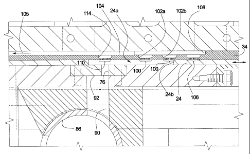
FIGURE 3 illustrates that the breather plate 34 includes a plurality of first
breather holes 100 located within two recesses 102a, 102b. The breather holes
100
have a diameter of between about .040" to about .065". The recesses 102a, 102b
allow for easier and more complete cleaning of food particles from the
breather holes
100 due to a reduced depth and lowered aspect ratio of the breather holes 100.
The
recesses 102a, 102b are open on top to an air channel or recycle channel 104
which is
configured to transport air and small food particles in the direction 105 back
to the food
product hopper (not shown) or other suitable location. The breather holes 100
are open
between the recesses 102a, 102b and the cavity 24a.

A further group of breather holes 106 are located within a recess 108. The
recess 108 is located at a position beyond a leading edge 24b of the cavity
24a when in
the filling position. During operation, the breather holes 106 are open the
cavity 24a to
the recess 108 after the mold plate 24 has begun return travel from the knock
out

position toward the filling position, but before the mold plate has completely
reached the
filling position. Filling of the cavity 24a and air breathing through the
holes 106 begins
when the fill slot is first uncovered by the moving cavity 24a, returning from
the knock
out position. The recess 108 is also open to the recycle channel 104.

6


CA 02405441 2002-10-07
WO 01/76375 PCT/US01/11421
The breather plate 34 also includes a plurality of second breather holes 110
located within a recess 114. The recess 114 is located close to the fill slot
76, such as
being in direct opposition to the fill slot. The recess 114 is also open into
the channel
104. The holes 110 have a diameter of between about .040" to about .065".

. The recesses 108 and 114 allow for easier and more complete cleaning of the
respective holes 106, 110 due to their reduced depth and lowered aspect ratio.
FIGURE 4 illustrates schematically the arrangement of the breather plate 34,
the

mold plate 24, and the food product filling apparatus 27. Food product 120 is
delivered
under pressure through the fill slot 76 of the insert plate 92 and into a
plurality of
cavities 24a. The first holes 100 are advantageously located within a first
area al of
the cavity 24a that is within one third of the cavity length L, the area al
extending
rearwardly from a leading edge of the cavity 24a. The second holes 110 are
advantageously located within a second area a2 of the cavity 24a that is
within one third
of the cavity length L, the area a2 extending forwardly from a trailing edge
of the cavity
24a.

A central area a3 of the cavity is advantageously one third the cavity length
L
and is substantially free of breather holes. The central area is
advantageously not less
than one inch in length.

The second holes 110 preferably do not number less than four holes per cavity
and do not constitute an aggregate open area more than 50% of the aggregate
open
area of the front holes 100.

According to one exemplary embodiment patty-forming machine having 3.875
inch diameter cavities, for each cavity 24a there are thirty five 0.040 inch
diameter

7


CA 02405441 2002-10-07
WO 01/76375 PCT/US01/11421
further breathing holes 106 within the recess 108, seventy 0.040 inch diameter
first
breather holes 100 within the recesses 102a, 102b (aggregate number), and nine
0.040
diameter second breather holes 110 within the recess 114.

According to the preferred embodiments, the recesses 102a, 102b, 108, 114 can
be circular, oval, rounded rectangular or other shape, in plan view.

The second holes 110 can advantageously be located directly facing the fill
slot
and/or slightly behind ('/e to'/Z inch) the fill slot. The relief of pressure
directly at and
toward the rear of the fill slot as the mold cavity is moving toward and past
the fill slot
opening eliminates or significantly reduces the presence of a ridge on the
formed food
patty. The forward location of the first holes 100 and the further breather
holes 106
ensure even and uniform filling of the entire cavity 24a with food product.

FIGURE 5 illustrates a patty 148 formed by a prior art molding plate lacking
second holes as per the present invention. A ridge 150 is typically formed
above the
inlet slot. In contrast, as shown in FIGURE 6, the patty 70 formed by a patty
forming
machine of the present invention is substantially flat and evenly shaped.

From the foregoing, it will be observed that numerous variations and
modifications may be effected without departing from the spirit and scope of
the
invention. It is to be understood that no limitation with respect to the
specific apparatus
illustrated herein is intended or should be inferred. It is, of course,
intended to cover by
the appended claims all such modifications as fall within the scope of the
claims.

8

Representative Drawing
A single figure which represents the drawing illustrating the invention.
Administrative Status

For a clearer understanding of the status of the application/patent presented on this page, the site Disclaimer , as well as the definitions for Patent , Administrative Status , Maintenance Fee  and Payment History  should be consulted.

Administrative Status

Title Date
Forecasted Issue Date 2009-07-14
(86) PCT Filing Date 2001-04-06
(87) PCT Publication Date 2001-10-18
(85) National Entry 2002-10-07
Examination Requested 2004-10-05
(45) Issued 2009-07-14
Deemed Expired 2018-04-06

Abandonment History

There is no abandonment history.

Payment History

Fee Type Anniversary Year Due Date Amount Paid Paid Date
Application Fee $300.00 2002-10-07
Maintenance Fee - Application - New Act 2 2003-04-07 $100.00 2002-10-07
Registration of a document - section 124 $100.00 2003-10-03
Maintenance Fee - Application - New Act 3 2004-04-06 $100.00 2004-03-08
Request for Examination $800.00 2004-10-05
Maintenance Fee - Application - New Act 4 2005-04-06 $100.00 2005-03-16
Maintenance Fee - Application - New Act 5 2006-04-06 $200.00 2006-03-21
Maintenance Fee - Application - New Act 6 2007-04-10 $200.00 2007-04-04
Maintenance Fee - Application - New Act 7 2008-04-07 $200.00 2008-03-06
Final Fee $300.00 2009-04-02
Maintenance Fee - Application - New Act 8 2009-04-06 $200.00 2009-04-06
Maintenance Fee - Patent - New Act 9 2010-04-06 $200.00 2010-01-20
Maintenance Fee - Patent - New Act 10 2011-04-06 $250.00 2011-01-24
Maintenance Fee - Patent - New Act 11 2012-04-10 $250.00 2012-04-03
Maintenance Fee - Patent - New Act 12 2013-04-08 $250.00 2013-04-01
Maintenance Fee - Patent - New Act 13 2014-04-07 $250.00 2014-03-31
Maintenance Fee - Patent - New Act 14 2015-04-07 $250.00 2015-04-01
Maintenance Fee - Patent - New Act 15 2016-04-06 $450.00 2016-04-04
Owners on Record

Note: Records showing the ownership history in alphabetical order.

Current Owners on Record
FORMAX, INC.
Past Owners on Record
LABRUNO, RONALD F.
Past Owners that do not appear in the "Owners on Record" listing will appear in other documentation within the application.
Documents

To view selected files, please enter reCAPTCHA code :


To view images, click a link in the Document Description column. To download the documents, select one or more checkboxes in the first column and then click the "Download Selected in PDF format (Zip Archive)" or the "Download Selected as Single PDF" button.

List of published and non-published patent-specific documents on the CPD .

If you have any difficulty accessing content, you can call the Client Service Centre at 1-866-997-1936 or send them an e-mail at CIPO Client Service Centre.


Document
Description 
Date
(yyyy-mm-dd) 
Number of pages   Size of Image (KB) 
Description 2008-05-27 8 303
Representative Drawing 2002-10-07 1 37
Cover Page 2003-01-27 1 60
Abstract 2002-10-07 1 62
Claims 2002-10-07 3 87
Drawings 2002-10-07 4 175
Description 2002-10-07 8 306
Claims 2002-10-08 5 163
Representative Drawing 2009-06-16 1 25
Cover Page 2009-06-16 1 59
Prosecution-Amendment 2008-05-27 4 111
Prosecution-Amendment 2004-10-05 1 38
PCT 2002-10-07 2 103
Assignment 2002-10-07 4 129
Correspondence 2003-01-23 1 24
Prosecution-Amendment 2002-10-08 6 174
PCT 2002-10-08 3 156
Assignment 2003-10-03 5 286
Prosecution-Amendment 2008-02-07 2 39
Correspondence 2009-04-02 2 55