Note: Descriptions are shown in the official language in which they were submitted.
CA 02406150 2002-10-02
Case ZLD-025
High-Pressure Film-Riding Seals for Rotating Shafts
The present invention relates to a seal and particularly to an improved high-
pressure film-
riding circumferential seal for restricting fluid flow between rotating and
stationary members, being
operable with high pressure differences thereacross and having long lifetime.
While usable with
all fluid systems, this invention is particularly useful for sealing
applications for dry gas
environments.
Background of the Invention
Circumferential sealing devices have gained wide acceptance in a variety of
applications,
including aero-derivative gas turbine engines and industrial turbo machinery.
The use of these
sealing devices in the industrial sector usually requires a seal life on the
order of five years (43,800
hours) minimum based on continuous operation. These circumferential seals are
contacting devices
being pressure relieved - not balanced - and their application is usually
limited to fifteen to twenty
prig thereacross to yield the required life on a typical industrial turbo
compressor. The low loading
on the seal, which is necessary for achieving the required life, is
accomplished by reducing the bore
dam sealing length to a reasonably low value. Spring loading, both radial and
axial, is likewise
controlled by low values. Forces which inhibit the ability of the seal ring to
track dynamic motion
of the shaft (due to static run-out or vibration) result predominantly from
the exposed clearance
between the rotating shaft sleeve and the inner diameter of the metallic seal
housing. Inertial forces
are also present due to the acceleration of the seal ring attempting to track
the rotor, but these are
generally not a problem as the seal ring is made of a material such as carbon
graphite with its low
associated density, thus low weight. In the past, attempts to provide a
circumferential film-riding
seal to achieve these objectives were made by Tascheaberg in Patent No.
3,575,424, which resulted
in a seal ring whose outer periphery was exposed to low pressure, and a
minimum clearance was
provided by a fixed housing component. Certain prior art structures have
formed secondary seals
with floating ring components, but these are associated only with non-rotating
housing parts, such
as the patent to Pope, No. 5,284,347; however, while this structure limits the
clearance for a
secondary seal, no one has provided a floating load ring primary gas seal
structure that minimizes
the clearance between a rotating shaft and a circumferentially disposed
floating load ring.
CA 02406150 2002-10-02
Case ZLD-025
Summary of the Invention
It is Applicant's intention to provide a circumferential fluid sealing device
(especially useful
for gaseous environments, i.e., formed with compressible fluids) having long
life and capable of
operating with an extremely high pressure drop thereacross, up to 250 psi or
more pressure
difference, by providing a segmented circumferential sealing ring engaging a
floating housing
portion, herein called a load ring, mounted in tandem with the segmented seal
ring, which serves
to help define the clearance between the rotating shaft and the seal. The bore
surface of the
segmented seal ring is provided with a sealing region adjacent a sealing dam
thereon and a bearing
region upstream thereof in the direction of fluid flow. In one embodiment of
this invention, the
bearing section is also provided with lift pockets to move the seal segments
away from the rotating
shaft (or sleeve mounted on the rotating shaft) to reduce the frictional loads
on the seal ring bore
surface. Since the seal ring, in accordance with this invention, is made from
a lighter weight
material such as carbon graphite or a ceramic composite, the sealing
components such as lift pockets
may be formed in the harder metallic parts such as a metallic shaft sleeve, so
that rubbing of the
parts does not destroy the lift pockets, thereby reducing the operating life
of the seat. The
combination of the segmented seal and a floating load ring, together with the
employment of lift
pockets in a normal bearing region of a circumferential film-riding fluid
seal, serve not only to
increase the lifetime of the seal but also to permit the seal to operate with
higher differential
pressures thereacross, which pressure differences (for gas seals) may well be
an order of magnitude
above the 15-20 psig normally envisioned for seals for these applications
having adequate lifetime.
This invention also provides a circumferential fluid seal with a reduced seal
gap along the seal even
with a higher pressure difference across it. In addition, an embodiment is
provided wherein the seal
ring and the floating load ring are essentially pressure-balanced.
- Brief Description of the Drawings
The specification includes claims which particularly point out and distinctly
claim the
subject matter which the Applicant considers to be his invention. A more
complete understanding
of the invention will be gained from the following detailed description, which
is given in
conjunction with the accompanying drawings, in which:
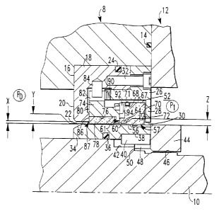
Fig. 1 is a cross-sectional schematic illustration of a seal system embodying
this invention,
2
CA 02406150 2002-10-02
Case ZLD-025
shown in conjunction with a fixed housing and a rotatable shaft with only the
shaft and seal system
above the shaft centerline being illustrated.
Fig. 2A is a plan view, reduced in size, illustrating the left side of the
seal ring of Fig. 1.
Fig. 2B is a plan view of the seal ring of Fig. 1, illustrating the right side
of the seal ring of
Fig. l, looking from right to left.
Fig. 3 is an enlarged sectional view through the seal ring of Fig. 2A, taken
along the lines
3-3 thereof.
Fig. 4 is a view similar to Fig. 3, taken along the lines 4-4 of Fig. 2A.
Fig. 5 is an enlarged sectional view of the seal ring of Fig. 2A, taken along
the lines 5-5
thereof.
Fig. 6 is an enlarged fragmentary plan view of the bore surface of the seal
ring of Figs. 1-5,
illustrating the joint between two of the segments thereof.
Fig. 7 is an enlarged sectional view of the seal ring of Fig. 2A, taken along
the lines 7-7
thereof.
Fig. 8 is a fragnentary plan view of a portion of the circumferential surface
of the shaft
sleeve employed in this invention, illustrating the lift pockets and feed
grooves for the bearing
segment of the segmented seal ring bore surface.
Fig. 9 is a sectional view through the shaft sleeve of Fig. 8, taken
essentially along the lines
9-9 thereof.
Fig. 10 is a plan view, reduced in size, of the right radial surface of the
floating load ring of
Fig. 1, illustrating the load ring surface looking from right to left in Fig.
1.
Fig. 11 is an enlarged sectional view through the load ring of Figs. 1 andl0.
Fig. 12 is an enlarged pressure diagram across a seal ring segment of Figs. 1
and 3.
Fig. 13 is a pressure diagram showing the forces across the load ring of the
embodiment of
Fig. 1.
Fig. 14 is a schematic sectional view similar to Fig. 1 of another embodiment
of this
invention, wherein a balanced seal is provided.
Fig. 15 is a pressure diagram showing the forces acting on the load ring of
the embodiment
of Fig. 14.
3
CA 02406150 2002-10-02
Case ZLD-025
Detailed Description of the Drawings
Referring now to the drawings, wherein like reference characters are used far
like elements
throughout and modifications of elements are designated by the same reference
characters primed,
Fig. 1 is a schematic sectional view through an embodiment of the seal system
of this invention and
includes a machine housing 8 shown schematically, containing a shaft 10
therein, which is rotatable.
While not illustrated in Fig. 1, it is clear that the housing 8 is essentially
a housing separating
different machine segments thereof, e.g., the housing of a compressor, and has
a rotatable shaft
therein extending through housing 8 to be engaged by a drive mechanism (not
shown) such as an
electric motor or turbine, and at the other end thereof to be engaged by a
working mechanism (not
shown) such as the blades of a compressor, etc.
In this example, housing 8 is connected to a removable housing segment I2,
which is
sealingly secured to housing 8 to prevent leakage therefrom by a suitable seal
such as O-ring 14, so
that no leakage from the interior of housing 8 passes through the juncture
between housing 8 and
segment 12. In this joint, the securing device (not shown) can be removed to
provide access to the
circumferential seal {to be described). Housing 8 is provided with a
downwardly extending shoulder
16, which is opposed to the housing segment 12 and which faces the rotatable
shaft 10. Positioned
within housing 8 and against shoulder 16 is an annular seal housing 18 having
a generally L-shaped
cross-section which is formed from metal and includes a downwardly extending
annular flange 20
having a central opening 22 therein. Leakage between seal housing 18 and
housing 8 is prevented
by the provision of an annular circumferential groove containing an O-ring 24
to prevent fluid flow
along the juncture between seat housing 18 and machine housing 8. A removable
cover ring 26 is
provided for seal housing I8; it is mounted at the end of seal housing 18
adjacent housing segment
12 and includes a downward annular flange 28 thereon, having an opening 30
therein, which is
generally in alignment with the opening 22 in flange 20 and axially spaced
there .from along shaft
10. The seal housing 18 and cover ring 26 are secured together by means of
bolts circumferentially
spaced thereabout such as cap bolt 32 (only one of which is shown) and form an
annular region
between the axially spaced flanges 20 and 28 for receiving components of the
seal system.
The shaft i0 is provided with a neck down portion which begins approximately
midway
between the flanges 20 and 28, when the shaft is assembled in housing 8, such
that the shaft may
receive a shaft sleeve 34, which is mounted on the outer surface thereof in a
leak-type manner by
4
CA 02406150 2002-10-02
Case ZLD-025
use of an outwardly extending circumferential groove and O-ring combination 36
to prevent leakage
in the space between the shaft 10 and sleeve 34. Rotation of the sleeve 34
relative to shaft 10 is
prevented by at least one recess 38 formed in shaft sleeve 34 aligned with a
complementary recess
42 in the shaft 10. A pin 40, which extends into both recesses 38 and 42, is
fixed in position by
suitable means such as by an annular lock nut 44, which is surrounded and
secured to the shaft by
suitable means such as by a threaded connection at 46. The shaft sleeve 34 has
a projection 48
engaging shaft shoulder 50 to maintain the sleeve 34 axially in position on
shaft 10.
Sleeve 34 is positioned on shaft 10 so that it passes through the openings 22
and 30 in axially
spaced flanges 20 and 28. Positioned in the opening between flanges 20 and 28
and adjacent flange
28 is a segmented primary seal ring 52. Segmented seal ring 52 is also
illustrated in Figs. 2A, 2B,
and 3-7. In this example (see Figs. 2A and 2B), segmented primary seal ring 52
is formed from
three segments 54, each of the segments including an offset tongue portion 55
and a diagonally cut
groove portion 58 (see Fig. 7), such that the tongue portion 55 also has a
diagonal face (not shown)
which is closely received in the groove 58 to prevent fluid flow either
radially or axially between
the segments 54. In this example, each seal ring segment 54 is formed entirely
from a material
having adequate abradability, low density, low weight, and adequate lubricity,
such as a carbon
graphite composite material or a ceramic material such as silicon nitrate or
silicon carbide. Seal
ring segments include a circumferential primary seal bore surface 56 thereon
positioned to engage
the outer circumferential surface of the shaft sleeve 34, with the latter
desirably being formed
entirely of metal and preferably having a hard-facing coating thereon at
positions of potentially
frictional engagement with the seal ring segments 54. It will be appreciated
that, while the use of
a separate shaft sleeve 34 for shaft 10 is illustrated herein, the shaft 10
itself may serve as the sealing
surface for the seal ring 52, and the outer circumferential surface of shaft
10 may have pockets 96
and feed grooves 98 (as will be described) formed thereon, thereby omitting
shaft. sleeve 34 from
the seal system.
The seal ring segments 54, when placed end to end, form a continuous
circumferential bore
surface 56 and a substantially continuous sealing dam 62 on the edge of the
bore surface remote
from the flange 28. Each of the seal ring segments has a substantially
continuous sealing dam
groove 64 on the bore surface 56 located adjacent the upstream side of the
sealing dam 62. The
sealing dam groove 64 terminates in each of the segments 54 at the female end
adjacem the groove
5
CA 02406150 2002-10-02 ""'
Case ZLD-025
58 and the tongue portion 55; thus except for a small segment of the bore
surface 56 at the juncture
of each of the segments 54, the sealing dam groove b4 is essentially
continuous.
As shown in Figs. 1, 5, and 6, the sealing dam groove 64 is in fluid
communication with the
rear or outward circumferential surface 67 of each seal ring segment 54 by a
plurality of openings
68, which are generally equidistantly spaced around the seal ring segments 54
in order to provide
fluid communication between the sealing dam groove 64 and the gas pressure en
the side 67 of the
seal ring segments 54. The last-mentioned surface 67, as will be explained
hereinafter, is exposed
to a higher pressure region P1 within the housing 8.
As shown in Figs. l, 3, 4, and 7, the seal ring segments 54 include in the
outer surface 67
thereof a circumferential recess 68 which extends around the periphery of the
seal ring 52 and
receives a garter spring 7I therein which biases the seal ring segments 54
radially inwardly toward
the shaft 10 and shaft sleeve 34. 1n addition, the seal ring segments 54 are
each provided with a
plurality of spring-receiving recesses ?0 located in the right radial surface
thereof, which, when the
seal is assembled, faces the flange 28 of the seal cover 26. As illustrated in
Fig. 2B, four such
recesses 70 are provided in each of the seal segments 54 and are served to
receive coil springs 72
(Fig. 1) in each of the openings to bias the seal ring segments 54 away from
flange 28 and toward
flange 20.
As shown in Fig. 1, an essentially unitary floating load ring 74 is interposed
between seal
ring segments 54 and flange 20 of seal ring housing I8. Floating load ring 74
desirably is formed
from a metal and includes a downwardly and axially facing recess 76 in the
inner circumferential
surface thereof, in which there is disposed an insert 78 which is fixedly
secured thereto by suitable
means such as by a shrink fit. Insert 78 extends radially inwardly of the
inner circumferential
surface of the load ring 74 and slightly outwardly of the radial surface 80 on
the side of the load ring
facing flange 20. The load ring insert ?8 is formed from a suitable material
such. as that forming
each of the seal ring segments 54 and is positioned to be the component of the
floating seal ring
such that= in the event of engagement with the shaft sleeve 34, the insert
would frictionally engage
the sleeve 34. Similarly, the radial surface of the insert ?8 adjacent the
flange 20 is positioned to
engage the latter to form an auxiliary seal, rather than having engagement of
the metallic floating
load ring 74 with the metallic flange 20. The outer radial surface of the load
ring 74 includes one
or more recesses 82 therein, which receive an anti-rotational pin 84 fixedly
secured in a recess in
6
CA 02406150 2002-10-02 -~~
Case ZLD-025
seal housing portion 18 and, with the pins 84, serving to prevent rotation of
the floating load ring
relative to the shaft 10 and shaft sleeve 34. The pins 84 are loosely received
within the recesses 82
to permit the seal ring to float without interference by the pins 84 and
thereby move a limited
amount in the radial direction and in the axial direction to permit assembly
of the seal system.
It will be seen, also in Fig. I, that the flange 20 has an annular projection
86 extending
toward load ring 74 at the lowest segment of the radial surface thereof,
whereby engagement of load
ring 74 with flange 20 to form the auxiliary seal 87 occurs only between load
ring insert 78 and
projection 86. It will be appreciated that the radial metallic surface on
projection 86 is finely
machined and desirably provided with a hard coating thereon to provide an
essentially flat surface.
The latter surface engages the adjacent radial surface of load ring insert 78,
whose engaging surface
is also machined andlor lapped to be essentially flat within a very low
tolerance range. Similarly,
all of the surfaces of load ring insert 78 are lapped essentially flat to
prevent any leakage between
the metal and non-metallic parts of load ring 74 and insert 78 and to maintain
an essentially constant
gap between the load ring's inner circumferential surface and the shaft sleeve
34. A biasing device
such as a wave spring 90 is interposed between the load ring ?4 and the cover
ring 26 to form the
auxiliary seal 87 by biasing the load ring 74 into engagement with the
projection 86 on flange 20.
The circumferential surface of the load ring 74 that faces flange 28 is
provided with a plurality of
anti-rotational pins 92, with at least one pin 92 being provided for each seal
segment 54, with the
pins 92 extending into recesses 94 (see Fig. 2A) in each of the seal segments
54 to prevent their
rotation relative to both the load ring ?4 and the shaft sleeve 34. When the
seal and load ring and
associated components are assembled into the seal housing 18, it will be seen
that the seal segments
54 are biased into engagement with the shaft sleeve 34, creating the primary
seal 57, and also with
the radial surface on the adjacent side of the floating load ring 74, forming
the secondary seal 61.
It will be appreciated that the area of engagement on the latter surface of
load ring 74 is finely
machined and hard-faced to minimize wear between the components as well as to
minimize leakage
therebetween. For the auxiliary seal 87, load ring 74 is biased against
shoulder 86 of flange 20 by
wave spring 90 and also by coil springs 72.
It will be appreciated that housing 8 has two regions identified by the
numerals P 1 and PO
of different pressures therein, with region P1 (on the right-hand side of Fig.
1) being of higher
pressure and region PO being maintained normally at a.lower pressure. It is
the intention of the seal
7
CA 02406150 2002-10-02
Case ZLD-025
system of this invention to maintain the pressure difference between regions P
l and P0. Thus, the
pressure in region P 1 is also present in the space between flanges 20 and 28
so that higher pressure
is on the radial side of the seal ring segments 54 located adjacent flange 28,
on the outer
circumferential sides of the seal ring 52 and of the load ring 74. Leakage of
fluid (gas) between the
flange 20 and its projection 86 and floating load ring 74 is prevented by
auxiliary seal 87 formed
therebetween, and leakage along the radial surface of load ring 74 closest to
the flange 28 and the
seal ring 52 is also prevented by frictional engagement of surfaces on those
components, forming
secondary seal 61 under the load of springs 72 and 90. Thus all leakage flow
is intended to pass
between regions Pl and PO only along the seal gap, i.e., between the bare
region 62 of seal ring 52
and the space between seal ring insert 78 and the outer circumferential
surfaces of sleeve 34. It is
intended that the primary seal S7 of this invention be a film-riding seal
operative for a long lifetime
(5 years or more) in an environment where the pressure difference between
regions P1 and PO may
be up to 250 psi or more (contrasting seals of this invention with those now
existing in industry for
these applications where the pressure difference is permitted to be only 20-30
psi) to achieve the
designed lifetime of 5 years. In furtherance of this purpose, it will be seen
that the flow path in the
bore region 56 of the seal ring 52 includes moving in the direction of fluid
flow in the upstream
circumferential bearing region between the arrows A (Fig. 6) and a lift region
adjacent sealing dam
60 downstream thereof created by high pressure fluid .flow across the sealing
dam, with high
pressure being introduced into the sealing dam groove 64 through passageways
68.
It is Applicant's specific intention that the forces tending to cause rubbing
between the
bearing region A of the seal ring 52 and the sleeve 34 be relieved in order to
ensure the long lifetime
at the pressure differences suggested above. In furtherance of this purpose, a
pressure relieve system
as illustrated in Figs. 8 and 9 is provided, wherein shallow,
circumferentially extending, relatively
short lift pockets 96 are provided in the bearing region A of the seal ring in
spaced relationship with
each other to reduce the friction or rubbing potential of that region of the
seal ring 52. la this
example, the lift pockets 96 are formed in the shaft sleeve 34 and axe fed
high pressure by axial
passageways 98 formed in shaft sleeve 34, which communicates with region Pl in
the housing 8.
In this example, the lift pockets 96 of Fig. 9 are aligned with each other,
although they may be offset
and overlapping in the bearing region, if desired, as long as they are
disparate from each other.
From Fig. 1 it will be seen that the passageways 98 underlie the portion of
the bearing region A of
8
CA 02406150 2002-10-02
Case ZLD-025
the seal segments 54 and extend upstream of the bearing region A to be exposed
to high pressure
(P 1 ). It will be appreciated that the material forming the sleeve 34 is a
harder material than that
forming the seal segments 54; thus, in the event of any rubbing engagement of
seal segments 54 with
shaft sleeve 34, any wear will occur on the softer seal segments 54, thereby
maintaining the integrity
of the lift pockets 96 (it being understood that such pockets axe very
shallow, on the order of 0.5
milli-inches or less, so that they could disappear in the event of extended
frictional engagement
between shaft sleeve 34 and the surface of the seal segments 54 if they were
formed on the segments
54. It is possible to form the passageways 98 and lift pockets 9b in the seal
ring segments 54
without departing from the spirit of this invention; however, it will be
appreciated that the creation
of the pockets 96 and passageways 98 in the harder shaft sleeve 34 will ensure
that these pockets
and passageways are retained throughout the lifetime of the seal, thus
providing a distinct advantage.
Figs. 10 and 11 depict the floating load ring 74 in plan view from the surface
thereof on
which the secondary seal 6 l is formed, with a sealing dam 100 provided
thereon adjacent the inner
circumferential bore surface of load ring 74. The sealing dam 100 is formed on
the metallic portion
of the load ring, and the dam is made as narrow as is practical to minimize
pressure loading. In
addition, pressure loading is further reduced by the provision of radial
grooves 102 on the surface
of load ring 74 positioned radially outwardly of sealing dam 100, which
grooves 102 connect with
three spaced circumferential grooves 104, the grooves 104 being aligned with
each of the seal ring
segments 54 when assembled. Thus grooves 104 are not interconnected with each
other, but are
separated by raised portions therebetween. Openings 93 are provided in the
load ring 74 to receive
the anti-rotation pins 92 therein and keyway 82 is provided to receive anti-
rotation pin 84 (Fig. 1 ),
as previously described. As mentioned above, insert 78 extends outwardly of
the surface of load
ring 74 on the side facing flange 28 and forms a shoulder 79 so that
frictional engagement between
insert 78 and the projection 86 on flange 20 occurs between projection 86 and
insert 78 rather than
a metal-to-meta1 contact. As shown in Fig. 11, a plurality of feed grooves 106
are machined on the
radial surface of the metallic portion of load ring ?4 that receives the
insert or liner 78, which serves
to exhaust any gas leakage which occurs at the shrink interface between the
metallic portion of the
load ring 74 and the insert 78 and prevents these components from separating.
By distribution of clearances in the seal system, the primary seal ring face
load can be greatly
reduced, i.e., the load on surface 61 of seal ring 52. In Fig. 1, the
clearances referred to are shown
9
," CA 02406150 2002-10-02 '
Case ZLD-025
with exaggerated dimension, and the radial clearance X comprises the required
clearance for
machine assembly and tolerance, i.e., between opening 22 at the inner
circumferential surface of
flange 20 and the outer circumferential surface of shaft sleeve 34. This
tolerance is designed to be
.035 inches (+). The floating load ring 74 is free to float in its chamber
with the seal housing 18 by
an amount ofX in the radial direction and rides over the rotating shaft sleeve
34 with a practical low
clearance Y between shaft sleeve 34 and load ring insert 78 of usually about
.005 inches (5 mils).
The clearance Y is set based upon practical machine-allowable vibration
alarm/trip setting -- in
other words, to allow free vibration of the shaft within the ring bore without
continuous contact.
The clearance between the metallic floating load ring 74 and shaft sleeve 34
is clearance Z, which
is greatly reduced, must be no less than clearance Y (between load ring insert
78 and shaft sleeve
34) to avoid contact, and is preferably between .005 and .010 inches (5-10
mils). This clearance
produces a total pressure-unbalanced Load on the primary seal ring against the
floating load ring.
This pressure load is now only a fraction of that which would be produced by
clearance X. Note
that the bore clearance at the sealing dam 60 is significantly lower than
these clearances, that is, on
the order of .0002 inches (.2 mils), remarkable for a primary circumferential
gas seal gap.
With reference to Fig. 12, wherein the force diagram of loads on the seal ring
segments 54
is illustrated during operation, it will be seen that there is a net upward
force on seal ring 52 formed
by the lift pockets in the bearing region A of the seal ring segments 54. Fig.
13 illustrates the load
on the load ring of Figs. l-10 and an unbalance in the side loads thereon by
the hatched area thereof.
Thus the load ring in this example is unbalanced.
In an alternative embodiment in Fig. I4, there is depicted a seal system of
this invention
wherein the load ring may be made to be balanced. Like components of Fig. 14
will not be further
described; however, it will be seen that in this example the shaft sleeve 34'
is provided on the outer
circumferential -surface with a downwardly extending shoulder 110 which faces
flange 20 and is
engaged by a nose portion 112 on shoulder 1 IO on the Ioad ring insert 78'. In
addition, a nose
portion 114 on the load ring insert 78' engages the outer surface of
projection 86' to form the
auxiliary seal 8T therebetween. The radial length of shoulder 110 is dependent
upon the radial
length of the nose portion 114 to achieve pressure balance on load ring 74'.
Furthermore, the load
ring 74' is provided with a projecting surface 116 extending toward flange 20,
and the keyway 82'
is formed on the side within projection 116, with anti-rotation pin 84'
extending into keyway 82'
CA 02406150 2002-10-02
Case ZLD-025
from flange 20. In this embodiment, the securing device for the cover 46' is a
snap ring 32'. Fig.
15 depicts the force diagram on the balanced load ring of Fig. 14 and shows
essentially pressure-
balanced loads thereon.
As pointed out above, the pressure load on the secondary seal at 61 and that
on seal 5T (Fig.
14) may be reduced by up to 25% when compared with the primary seal pressure
loads in current
circumferential seals, thus providing a long-lived film-riding circumferential
fluid seal capable of
operating at pressure differences, when employed in a gaseous environment, of
more than 1'12 orders
of magnitude greater than current circumferential sealing technology used in
the field. Furthermore,
the film-riding geometry in the bearing region allows the contact-free
operation to achieve long life.
The bearing and sealing functions are totally separate entities and not
dependent on one another.
The fluid bearings are fed high-pressure fluids by the deep feed grooves,
while the sealing dam and
the bore are fed the same via the drilled passageways 68 in the seal ring
segments 54. Inhibiting
forces due to rotor-ta=housing clearances are reduced to extremely low values
by virtue of the use
of the floating load ring 74 or 74'. The latter load ring ?4 or 74' also
functions as a back-up sealing
device with a restricted clearance, i.e., as a floating bushing, in the event
of operational mishap. As
shown, the floating load ring can be designed to be pressure-balanced to
reduce inhibiting forces
to nearly nil. The operation of a circumferential seal in an environment with
pressure differences
which represent more than a fifteen time increase over existing technology now
rivals the pressure
range that is achievable today only by the use of face-type seals.
High shaft speed testing has occurred for 5.6"-diameter seals of this
invention in a gaseous
environment at a pressure difference to-date of up to 225 psi. After 75 hours
of testing, minimal
contact between either the seal ring segments 54 and the shaft sleeve 34, or
the floating ring insert
78 with the shaft sleeve 34, has been observed No wear has been evidenced.
It is specifically intended that this invention not be limited to the
particular embodiments
disclosed as the best mode contemplated for carrying out this invention, but
that the invention will
include all embodiments falling within the scope of the appended Claims.
11