Language selection

Search

Patent 2406416 Summary

Third-party information liability

Some of the information on this Web page has been provided by external sources. The Government of Canada is not responsible for the accuracy, reliability or currency of the information supplied by external sources. Users wishing to rely upon this information should consult directly with the source of the information. Content provided by external sources is not subject to official languages, privacy and accessibility requirements.

Claims and Abstract availability

Any discrepancies in the text and image of the Claims and Abstract are due to differing posting times. Text of the Claims and Abstract are posted:

  • At the time the application is open to public inspection;
  • At the time of issue of the patent (grant).
(12) Patent Application: (11) CA 2406416
(54) English Title: CROP HARVESTING MACHINE WITH RECOIL ACTION ON IMPACT WITH AN OBSTACLE
(54) French Title: MOISSONNEUSE EQUIPEE D'UN DISPOSITIF DE RECUL EN CAS D'IMPACTS CONTRE DES OBSTACLES
Status: Dead
Bibliographic Data
(51) International Patent Classification (IPC):
  • A01D 47/00 (2006.01)
  • A01B 61/00 (2006.01)
  • A01B 61/02 (2006.01)
  • A01D 75/18 (2006.01)
(72) Inventors :
  • SNIDER, GEOFFREY U. (Canada)
  • DUNN, JAMES THOMAS (Canada)
(73) Owners :
  • MACDON INDUSTRIES LTD. (Canada)
(71) Applicants :
  • MACDON INDUSTRIES LTD. (Canada)
(74) Agent: ADE & COMPANY
(74) Associate agent:
(45) Issued:
(22) Filed Date: 2002-10-03
(41) Open to Public Inspection: 2004-04-03
Availability of licence: N/A
(25) Language of filing: English

Patent Cooperation Treaty (PCT): No

(30) Application Priority Data: None

Abstracts

English Abstract


A crop harvesting machine includes a crop harvesting header mounted
on a transport vehicle for carrying the header across the ground with at least
one
upper connecting link extending from the vehicle frame to an upper frame
member
and two support arms each extending from a front end at the header to a rear
end
pivotally mounted on the vehicle frame and arranged at a height below the
upper
link. Each support arm has a respective float spring connected thereto at a
pivot
thereon forwardly of the rear end and extending therefrom to the vehicle frame
for
applying a lifting force on the support arm. Each support arm has a pivot
connection
at the rear end defined by a pivotal link connected at a forward end to the
frame by a
resilient bushing and at a rear end by a similar bushing to the rear end of
the support
arm. The pivotal link is inclined upwardly and rearwardly in the normal
operating
position and thus pivots downwardly and rearwardly on an impact so as to
absorb
the impact on the crop cutter and tending to cause pivotal movement of the
support
arm relative to the pivot connection to the float spring to effect lifting
movement of
the cutter relative to the ground.


Claims

Note: Claims are shown in the official language in which they were submitted.


15

CLAIMS:

1. A crop harvesting machine comprising:
a crop harvesting header having:
a header frame structure arranged for movement in a direction
of working movement across ground carrying a crop to be harvested;
a crop cutter arranged across the header frame structure for
cutting the crop;
the header frame structure including an upper frame member
and a plurality of lower frame elements arranged such that an impact on the
crop
cutter as the header moves forwardly across the ground tends to move the lower
frame elements rearwardly;
a transport vehicle for carrying the header across the ground having:
a vehicle frame;
ground wheels for supporting the frame in transport across the
ground;
at least one upper connecting link extending from the vehicle
frame to the upper frame member;
and a connection between the vehicle frame and at least one of
the lower frame elements for providing a lifting force on the header frame,
the
connection including at least one support arm at a height below the upper link
extending from the vehicle frame generally forwardly to the lower frame
elements;
the connection between the vehicle frame and the at least one of the
lower frame elements being arranged such that an impact on the crop cutter
tending


16

to move the lower frame elements rearwardly is absorbed by rearward movement
of
the header relative to the vehicle and also causes lifting movement of the
cutter
relative to the ground.

2. The crop harvesting machine according to Claim 1 wherein the
connection is arranged such that the rearward movement of the header relative
to
the vehicle causes said lifting movement of the cutter relative to the ground.

3. The crop harvesting machine according to Claim 1 wherein the
connection includes a linkage which is arranged such that the rearward
movement of
the linkage causes said lifting movement of the cutter relative to the ground.

4. The crop harvesting machine according to Claim 3 wherein the
linkage is provided between the at least one support arm and the vehicle
frame.

The crop harvesting machine according to Claim 1 wherein the
at least one support arm is mounted on the vehicle frame for pivotal movement
upwardly and downwardly about a horizontal pivot axis and wherein there is
provided a lift link pivotally connected between the support arm and the
vehicle
frame for pivoting the at least one support arm in a direction tending to lift
a forward
end of the at least one support arm and therefore the header carried thereon.

6. The crop harvesting machine according to Claim 5 wherein the
connection includes a linkage which is arranged such that the rearward
movement of
the header causes pivotal movement of the at least one support arm generating
said
lifting movement of the cutter relative to the ground.

7. The crop harvesting machine according to Claim 6 wherein the
linkage is provided between the at least one support arm and the vehicle frame


17
tending to pivot the support arm about the lift link.
8. The crop harvesting machine according to Claim 1 wherein the
at least one support arm is pivotally mounted on the vehicle frame at a rear
end of
the at least one support arm and wherein the lift link is arranged in front of
the rear
end.
9. The crop harvesting machine according to Claim 8 wherein the
lift link is a float spring.
10. The crop harvesting machine according to Claim 3 wherein the
linkage comprises a pivotal link pivotally connected at one end to the vehicle
frame
and pivotally connected at the other end to the support arm and arranged such
that
rearward movement of the support arm is taken up by pivotal movement of the
link
which causes pivotal movement of the support arm.
11. The crop harvesting machine according to Claim 10 wherein the
pivotal link is pivotally connected to the vehicle frame by a first resilient
bushing
capable of angularly limited pivotal movement and to the support arm by a
second
resilient bushing capable of angularly limited pivotal movement and where the
pivotal movement of the support arm relative to the vehicle frame is taken up
partly
by each of the first and second resilient bushings.
11. The crop harvesting machine according to Claim 10 wherein the
pivotal link is arranged such that, prior to impact forces moving the support
arm
rearwardly, the link is arranged to extend from the vehicle frame upwardly and
rearwardly to the support arm such that rearward movement of the support arm
is
taken up by rearward movement of the rear end of the link which causes
downward


18
movement of the rear end of the link causing downward movement of the rear end
of
the support arm.
12. A crop harvesting machine comprising:
a crop harvesting header having:
a header frame structure arranged for movement in a direction
of working movement across ground carrying a crop to be harvested;
a crop cutter arranged across the header frame structure for
cutting the crop;
the header frame structure including an upper frame member
and a plurality of lower frame elements arranged such that an impact on the
crop
cutter as the header moves forwardly across the ground tends to move the lower
frame elements rearwardly;
a transport vehicle for carrying the header across the ground having:
a vehicle frame;
ground wheels for supporting the frame in transport across the
ground;
at least one upper connecting link extending from the vehicle
frame to the upper frame member;
and two support arms each extending from a front end at the header to
a rear end pivotally mounted on the vehicle frame and arranged at a height
below
the upper link extending from the vehicle frame generally forwardly to the
lower
frame elements;
each support arm having a respective float spring connected thereto at


19
a pivot thereon forwardly of the rear end and extending therefrom to the
vehicle
frame for applying a lifting force on the support arm;
each support arm having a pivot connection at the rear end arranged
such that an impact on the crop cutter tending to move the lower frame
elements
rearwardly is absorbed by rearward movement of the a support arm relative to
the
vehicle which rearward movement causes pivotal movement of the support arm
relative to the pivot connection to the float spring to effect lifting
movement of the
cutter relative to the ground.
13. The crop harvesting machine according to Claim 12 wherein the
pivot comprises a pivotal link pivotally connected at one end to the vehicle
frame and
pivotally connected at the other end to the support arm and arranged such that
rearward movement of the support arm is taken up by pivotal movement of the
link
which causes pivotal movement of the support arm.
14. The crop harvesting machine according to Claim 13 wherein the
pivotal link is pivotally connected to the vehicle frame by a first resilient
bushing
capable of angularly limited pivotal movement and to the support arm by a
second
resilient bushing capable of angularly limited pivotal movement and where the
pivotal movement of the support arm relative to the vehicle frame is taken up
partly
by each of the first and second resilient bushings.
15. The crop harvesting machine according to Claim 13 wherein the
pivotal link is arranged such that, prior to impact forces moving the support
arm
rearwardly, the link is arranged to extend from the vehicle frame upwardly and
rearwardly to the support arm such that rearward movement of the support arm
is


20
taken up by rearward movement of the rear end of the link which causes
downward
movement of the rear end of the link causing downward movement of the rear end
of
the support arm.
16. A crop harvesting machine comprising:
a crop harvesting header having:
a header frame structure arranged for movement in a direction
of working movement across ground carrying a crop to be harvested;
a crop cutter arranged across the header frame structure for
cutting the crop;
the header frame structure including an upper frame member
and a plurality of lower frame elements arranged such that an impact on the
crop
cutter as the header moves forwardly across the ground tends to move the lower
frame elements rearwardly;
a transport vehicle for carrying the header across the ground having:
a vehicle frame;
ground wheels for supporting the frame in transport across the
ground;
at least one upper connecting link extending from the vehicle
frame to the upper frame member;
and two support arms each extending from a front end at the header to
a rear end pivotally mounted on the vehicle frame and arranged at a height
below
the upper link extending from the vehicle frame generally forwardly to a
respective
one of the lower frame elements;


21
each support arm having a respective float spring connected thereto at
a pivot thereon forwardly of the rear end and extending therefrom to the
vehicle
frame for applying a lifting force on the support arm;
each support arm having a pivot connection at the rear end defined by
a pivotal link pivotally connected at one end to the vehicle frame and
pivotally
connected at the other end to the support arm.
17. The crop harvesting machine according to Claim 16 wherein the
pivotal link is pivotally connected to the vehicle frame by a first resilient
bushing
capable of angularly limited pivotal movement and to the support arm by a
second
resilient bushing capable of angularly limited pivotal movement and where the
pivotal movement of the support arm relative to the vehicle frame is taken up
partly
by each of the first and second resilient bushings.
18. The crop harvesting machine according to Claim 16 wherein the
pivotal link is arranged such that, prior to impact forces moving the support
arm
rearwardly, the link is arranged to extend from the vehicle frame upwardly and
rearwardly to the support arm such that rearward movement of the support arm
is
taken up by rearward movement of the rear end of the link which causes
downward
movement of the rear end of the link causing downward movement of the rear end
of
the support arm.

Description

Note: Descriptions are shown in the official language in which they were submitted.


t
CA 02406416 2002-10-03
CROP HARVESTING MACHINE WITH RECOIL ACTION ON IMPACT
WITH AN OBSTACLE
This invention relates to a crop harvesting machine including a header
mounted on a vehicle.
BACKGROUND OF THE INVENTION
It is well known to provide a tractor arrangement for transport of a
header across the ground for harvesting of a crop standing on the ground.
Various
types of header are available for this purpose depending upon the type and
quality
of crop.
Many headers of this type are arranged so that the cutting
arrangement is as close as possible to the ground giving the possibility of a
damaging impact with obstacles on the ground, primarily rocks. It is therefore
desirable to provide in some cases the possibility of a recoil action which
allows the
header to move rearwardly relative to the tractor upon an impact thus taking
up
some of the force to reduce the possibility of damage.
One arrangement which allows a recoil action has a header which is in
effect suspended in a pendulum manner from a suitable support above the header
on the tractor so that impact allows the header to swing rearwardly about a
pivot axis
above the header. An example of such an arrangement is shown in the brochure
by
Vermeer of their "Discpro" mower conditioner. However the location of the
pivot axis
above the header is inconvenient and makes the design difficult or impossible
for
headers that include a reel, as is required in many end uses.

r
CA 02406416 2002-10-03
2
SUMMARY OF THE INVENTION
It is one object of the present invention to provide an improved
harvesting machine which provides an improved link between the header and the
vehicle frame.
According to a first aspect of the invention there is provided a crop
harvesting machine comprising:
a crop harvesting header having:
a header frame structure arranged for movement in a direction of
working movement across ground carrying a crop to be harvested;
a crop cutter arranged across the header frame structure for cutting the
crop;
the header frame structure including an upper frame member and a
plurality of lower frame elements arranged such that an impact on the crop
cutter as
the header moves forwardly across the ground tends to move the lower frame
elements rearwardly;
a transport vehicle for carrying the header across the ground having:
a vehicle frame;
ground wheels for supporting the frame in transport across the ground;
at least one upper connecting link extending from the vehicle frame to
the upper frame member;
and a connection between the vehicle frame and the lower frame
elements for providing a lifting force on the header frame, the connection
including at
least one support arm at a height below the upper link extending from the
vehicle

CA 02406416 2002-10-03
3
frame generally forwardly to the lower frame elements;
the connection between the vehicle frame and the lower frame
elements being arranged such that an impact on the crop cutter tending to move
the
lower frame elements rearwardly is absorbed by rearward movement of the header
relative to the vehicle and also causes lifting movement of the cutter
relative to the
ground.
The arrangement described herein is primarily designed for use with a
header of the type using a sickle knife as the cutting system since such
sickle knifes
are particularly prone to damage on impact. However the present invention is
not
intended to be limited to such cutting devices and the header can use other
cutting
devices well known to one skilled in the art of various different types.
The vehicle as described herein after is generally of the type
conventionally used as a swather tractor which has two front wheels each
mounted
on a respective leg and driven hydraulically so the leg provides a suitable
support for
the forwardly extending lower lift arm or support arm. However other
arrangements
of vehicle can be used and the linkage between the support arm and the tractor
frame as described in detail herein after, can be utilised on other
arrangements of
tractor vehicle.
Preferably the connection is arranged such that the rearward
movement of the header relative to the vehicle causes said lifting movement of
the
cutter relative to the ground.
Preferably the connection includes a linkage which is arranged such
that the rearward movement of the linkage causes said lifting movement of the
cutter

CA 02406416 2002-10-03
4
relative to the ground.
Preferably the linkage is provided between the at feast one support
arm and the vehicle frame.
Preferably the at least one support arm is mounted on the vehicle
frame for pivotal movement upwardly and downwardly about a horizontal pivot
axis
and wherein there is provided a lift link pivotally connected between the
support arm
and the vehicle frame for pivoting the at least one support arm in a direction
tending
to lift a forward end of the at least one support arm and therefore the header
carried
thereon.
Preferably the connection includes a linkage which is arranged such
that the rearward movement of the header causes pivotal movement of the at
least
one support arm generating said lifting movement of the cutter relative to the
ground.
Preferably the linkage is provided between the at least one support
arm and the vehicle frame tending to pivot the support arm about the lift
link.
Preferably the at least one support arm is pivotally mounted on the
vehicle frame at a rear end of the at least one support arm and wherein the
lift link is
arranged in front of the rear end.
Preferably the lift link is a float spring. The spring force can be
provided by any form of spring including hydraulic cylinders, coil springs or
leaf
springs.
Preferably the linkage comprises a pivotal link pivotally connected at
one end to the vehicle frame and pivotally connected at the other end to the
support
arm and arranged such that rearward movement of the support arm is taken up by

CA 02406416 2002-10-03
pivotal movement of the link which causes pivotal movement of the support arm.
Preferably the pivotal link is pivotally connected to the vehicle frame by
a first resilient bushing capable of angularly limited pivotal movement and to
the
support arm by a second resilient bushing capable of angularly limited pivotal
5 movement and where the pivotal movement of the support arm relative to the
vehicle
frame is taken up partly by each of the first and second resilient bushings.
Preferably the pivotal link is arranged such that, prior to impact forces
moving the support arm rearwardly, the link is arranged to extend from the
vehicle
frame upwardly and rearwardly to the support arm such that rearward movement
of
the support arm is taken up by rearward movement of the rear end of the link
which
causes downward movement of the rear end of the link causing downward
movement of the rear end of the support arm.
According to a second aspect of the invention there is provided a crop
harvesting machine comprising:
a crop harvesting header having:
a header frame structure arranged for movement in a direction of
working movement across ground carrying a crop to be harvested;
a crop cutter arranged across the header frame structure for cutting the
crop;
the header frame structure including an upper frame member and a
plurality of lower frame elements arranged such that an impact on the crop
cutter as
the header moves forwardly across the ground tends to move the lower frame
elements rearwardly;

CA 02406416 2002-10-03
6
a transport vehicle for carrying the header across the ground having:
a vehicle frame;
ground wheels for supporting the frame in transport across the ground;
at least one upper connecting link extending from the vehicle frame to
the upper frame member;
and two support arms each extending from a front end at the header to
a rear end pivotally mounted on the vehicle frame and arranged at a height
below
the upper link extending from the vehicle frame generally forwardly to the
lower
frame elements;
each support arm having a respective float spring connected thereto at
a pivot thereon forwardly of the rear end and extending therefrom to the
vehicle
frame for applying a lifting force on the support arm;
each support arm having a pivot connection at the rear end arranged
such that an impact on the crop cutter tending to move the lower frame
elements
rearwardly is absorbed by rearward movement of the a support arm relative to
the
vehicle which rearward movement causes pivotal movement of the support arm
relative to the pivot connection to the float spring to effect lifting
movement of the
cutter relative to the ground.
According to a third aspect of the invention there is provided a crop
harvesting machine comprising:
a crop harvesting header having:
a header frame structure arranged for movement in a direction of
working movement across ground carrying a crop to be harvested;

CA 02406416 2002-10-03
7
a crop cutter arranged across the header frame structure for cutting the
crop;
the header frame structure including an upper frame member and a
plurality of lower frame elements arranged such that an impact on the crop
cutter as
the header moves forwardly across the ground tends to move the lower frame
elements rearwardly;
a transport vehicle for carrying the header across the ground having:
a vehicle frame;
ground wheels for supporting the frame in transport across the ground;
at least one upper connecting link extending from the vehicle frame to
the upper frame member;
and two support arms each extending from a front end at the header to
a rear end pivotally mounted on the vehicle frame and arranged at a height
below
the upper link extending from the vehicle frame generally forwardly to the
lower
frame elements;
each support arm having a respective float spring connected thereto at
a pivot thereon forwardly of the rear end and extending therefrom to the
vehicle
frame for applying a lifting force on the support arm;
each support arm having a pivot connection at the rear end defined by
a pivotal link pivotally connected at one end to the vehicle frame and
pivotally
connected at the other end to the support arm.
BRIEF DESCRIPTION OF THE DRAWINGS
One embodiment of the invention will now be described in conjunction

CA 02406416 2002-10-03
with the accompanying drawings in which:
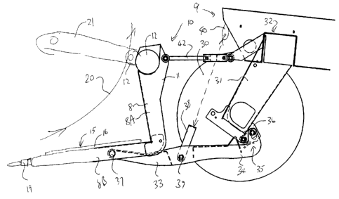
Figure 1 is a side elevational view of a crop harvesting machine
according to the present invention showing schematically the forward end of a
tractor vehicle and showing schematically the components of the header mounted
thereon.
Figure 2 is a side elevational view of the machine of Figure 1 on the
large scale showing the pivot connection between the rear end of the support
arm
and the vehicle frame and showing the pivot connection in a normal operating
position.
Figure 3 is a side elevational view similar to that of Figure 2 showing
the pivot connection after an impact of the header with an obstacle in which
the pivot
connection has operated to absorb the impact forces and to pivot the header
upwardly.
Figure 4 is a cross sectional view along the lines 4-4 of Figure 3.
In the drawings like characters of reference indicate corresponding
parts in the different figures.
DETAILED DESCRIPTION
In Figure 1 is shown an embodiment of a header according to the
present invention with a number of the elements being shown schematically
since
the general construction of such headers is well known to one skilled in the
art. The
header 10 includes a header frame 11 having a main frame tube 12 extending
across the width of the header between two end frames one of which is shown at
13
and the other of which is of course at the other end and therefore not visible
in the

CA 02406416 2002-10-03
9
elevation of Figure 1. The main tube 12 is suitably supported and attached on
a
propulsion vehicle in a manner so that the header frame can be moved forwardly
across the ground in cutting a standing crop. The end frame 13 extends
forwardly
from the main tube 12 to a forward nose section 14. The main tube 12 carries a
plurality of frame bars which extend downwardly and forwardly for supporting a
table
of the header onto which crop material is deposited after cutting. The
structural
elements defining the frame bars on the table are not shown for convenience of
illustration since again these are well known to one skilled in the art and
can vary in
accordance with engineering considerations.
10 On the table 15 is provided a crop conveyor 16 which is arranged to
transport the crop after cutting across the width of a header to a discharge
location.
In the embodiment shown the conveyor is provided as a draper canvas 17 mounted
on rollers 18. Other embodiments can use alternative crop transportation
systems
and primarily an auger which is commonly used as an alternative for the draper
15 system. The embodiments of the present invention are not limited to either
of the
different types of header.
At the front of the table 15 is provided a cutter bar generally indicated
at 19 which is again only shown schematically since the construction of this
is well
known to one skilled in the art. The cutter bar shown provides a sickle knife
in
guards which reciprocates back and forth in a cutting action on the standing
crop so
that the crop is deposited on the draper for transportation to the discharge
location.
When used on a combine harvester the discharge location is
associated with a crop transfer system which transfers the crop rearwardly
into the

CA 02406416 2002-10-03
feeder house of the combine. Headers of this type can of course also be used
as a
swather where the discharge location simply discharges the crop onto the
ground in
a swath or through a crop conditioner onto the ground.
The header further includes a reel generally indicated at 20. The reel
5 20 includes mounting arms 21 pivoted on a suitable mounting 22 adjacent the
tube
12 so that the arms project forwardly from the frame to a position over the
end frame
elements 13 so as to provide support for the reel extending the header above
the
cutter bar. Each arm is movable in its pivotal action by a suitable drive
actuator 23.
The number of arms can vary in accordance with engineering
10 requirements depending upon the width of the header. Some headers have only
arms at the ends and some have additional arms intermediate the ends to
provide
the necessary support.
The vehicle generally indicated at 9 includes a pair of front wheels 30
each of which is carried on a respective depending leg 31 forming part of a
frame
structure 32. The front wheel drive generally driven by a hydraulic motor (not
shown). The header is mounted on the tractor primarily by a pair of support
arms
33. Each of the support arms is pivoted at its rear end 34 by the pivot
coupling 35 to
a frame element 36 of the leg 31. Each of the support arms has a forward end
37
which engages the header at a position generally underneath the header or the
bottom of the arms 8 of the header.
In the conventional header shown where the arms 8 include a
generally vertical section 8A and a generally horizontal section 8D, the
support arms
33 has the forward end underneath the horizontal section 8D within a channel

CA 02406416 2002-10-03
11
defining the horizontal section 8B. The support arms are each lifted by a
respective
lift link 38 which extends from a pivot point 39 on the support arm fonNardly
of the
rear end generally upwardly and rearwardly to a suitable mounting
schematically
indicated at 40 on the vehicle. The lift link in most cases forms a float
spring which
carries the majority of the weight of the header leaving a small proportion of
the
weight of the header to rest on the ground. However the float springs can
generally
be adjusted so as to carry the header at a raised height where it is required
that the
cutter bar be spaced from the ground, depending upon crop conditions. One or
more upper links 42 is provided between a suitable frame element on the
vehicle
and an upper part of the frame generally adjacent the tube 12.
Thus the header is mounted on the vehicle by way of the lower support
arms and the one or more upper links which allow the header to float upwardly
and
downwardly and generally to twist about a horizontal axis in the direction of
travel.
The above general arrangement of header mounting on a tractor is conventional
and
the improvement herein relates to the construction of the pivot coupling 35
which is
arranged in a particular improved manner which has a number of advantages as
described herein.
The conventional arrangement by which the rear end 34 of the support
arm 33 is connected to the frame is generally a single pivot point defined by
a
suitable pivot pin. In the present arrangement, however, the single pivot
point is
replaced by a link 42 which is pivoted at its forward end on the frame element
36
and at its rearward end on the rear end 34 of the arm 33. In general the link
42 is
arranged in the normal operating position shown in figure 3 so that it is
inclined

CA 02406416 2002-10-03
12
upwardly and rearwardly at an angle A. Thus rearward movement in the direction
D
of the arm 33 caused by a rearward impact on the cutter bar moves the rear end
34
in the rearward direction which forces the link 42 downwardly and rearwardly
as it
moves in an arc around the front pivot 43 on the frame 36. This rearward and
downward movement of the rear end of the arm 34 causes the arm to pivot about
the pivot pin 39 of the float spring in a clockwise direction C. This pivotal
movement
in the clockwise direction acts to lift the forward end 37 of the support arm
causing
the header also to be lifted vertically upwardly. In practice the amount of
downward
movement provided by the pivotal action of the link 42 is of the order of 40
mm
providing a vertical lifting movement at the cutter bar of the order of 40 mm.
The construction of the link is best shown in Figure 4. The arm 34 is
thus formed of two side plates 34A and 34B of a channel member with a
generally
horizontal section 34C and a raised rear section 34D directly at the rear end
which
extends upwardly from the horizontal section 34C to provide a raised section
for
receiving the pivot mounting to the link 42. The link 42 is defined by two
side plates
42A and 42B which are connected together by the outside tube 50 and 51 of a
resilient bushing 52 and 53 respectively. Thus the tubes 50 and 51 and the
side
plates 42A and 42B form a rigid structure defining the link 42.
The frame section 36 is again defined by two side plates 36A and 36B.
The resilient or rubber bushing 52 includes a pin 60 which is connected to the
sleeve
50 by a resilient rubber annular connection 61. The pin 60 is clamped between
the
plates 36A and 36B of the frame member 36. Similarly the side walls 34A and
34B
are engaged by a pin 62 which clamps to the side walls 34A and 34B of the rear
end

CA 02406416 2002-10-03
13
of the arm. Thus the resilient bushing 52 defined by the pin 60 and the sleeve
50
allows limited angular pivotal movement of the link 42 relative to the frame
36.
Similarly the resilient bushings 53 defined by the sleeve 51 and the pin 62
together
with a resilient connection 64 allows limited angular rotation of the link 42
relative to
the rear end 34. The total amount of pivotal movement required between the two
resilient bushings is a total of the order of 40 degrees and this is
automatically
balanced between the two resilient bushings since they are generally
symmetrical.
This reduces the required angular rotation of each of the bushings to an angle
of the
order of 20 degrees which is well within design limits of resilient bushings
of this
general type.
The bushings can therefore accommodate both the pivotal movement
necessary to recoil and pivot in the impact pivoting action and also can
accommodate the necessary general pivotal movement which is provided for the
lifting and lowering of the support arms to raise the header to the required
position.
The pin 60 is free to move upwardly and downwardly without
interference with the arm 33 since it is located above the horizontal section
34C of
the arm 33. The pin 62 is free to move upwardly and downwardly relative to the
frame 36 since it is located within slots 68 provided in the plates 36A and
36B of the
frame 36. The slots are thus arcuate and have a length sufficient to
accommodate
movement of the pin 62 from its raised initial position at the angle of
incline to a
position horizontally rearward of the pin 60 in response to the impact. The
plates of
the frame 36 are held spaced form the plates forming the arm 33 by suitable
spacers
70 located on the pin 62.

CA 02406416 2002-10-03
14
The pivot link 42 has the advantage that it absorbs impact at the cutter
bar and the same time drives the cutter bar upwardly due to the downward
movement of the rear end of the support arm.
The pivot link is rubber mounted by the resilient bushings to reduce
vibration transmission and to allow some lateral movement of the lower support
arm.
The secondary or pivotal link also allows greater pivotal rotation of the
lower arm since the rotation is equally split between the two rubber bushings
while
allowing the use of rubber bushings which are less prone to wear and require
less
maintenance.
Since various modifications can be made in my invention as herein
above described, and many apparently widely different embodiments of same made
within the spirit and scope of the claims without departing from such spirit
and
scope, it is intended that all matter contained in the accompanying
specification shall
be interpreted as illustrative only and not in a limiting sense.

Representative Drawing
A single figure which represents the drawing illustrating the invention.
Administrative Status

For a clearer understanding of the status of the application/patent presented on this page, the site Disclaimer , as well as the definitions for Patent , Administrative Status , Maintenance Fee  and Payment History  should be consulted.

Administrative Status

Title Date
Forecasted Issue Date Unavailable
(22) Filed 2002-10-03
(41) Open to Public Inspection 2004-04-03
Dead Application 2005-10-03

Abandonment History

Abandonment Date Reason Reinstatement Date
2004-10-04 FAILURE TO PAY APPLICATION MAINTENANCE FEE

Payment History

Fee Type Anniversary Year Due Date Amount Paid Paid Date
Application Fee $300.00 2002-10-03
Registration of a document - section 124 $100.00 2002-11-22
Owners on Record

Note: Records showing the ownership history in alphabetical order.

Current Owners on Record
MACDON INDUSTRIES LTD.
Past Owners on Record
DUNN, JAMES THOMAS
SNIDER, GEOFFREY U.
Past Owners that do not appear in the "Owners on Record" listing will appear in other documentation within the application.
Documents

To view selected files, please enter reCAPTCHA code :


To view images, click a link in the Document Description column. To download the documents, select one or more checkboxes in the first column and then click the "Download Selected in PDF format (Zip Archive)" or the "Download Selected as Single PDF" button.

List of published and non-published patent-specific documents on the CPD .

If you have any difficulty accessing content, you can call the Client Service Centre at 1-866-997-1936 or send them an e-mail at CIPO Client Service Centre.


Document
Description 
Date
(yyyy-mm-dd) 
Number of pages   Size of Image (KB) 
Drawings 2002-10-03 3 56
Description 2002-10-03 14 565
Claims 2002-10-03 7 256
Abstract 2002-10-03 1 32
Cover Page 2004-03-08 1 49
Representative Drawing 2003-01-20 1 13
Correspondence 2002-11-18 1 25
Assignment 2002-10-03 3 80
Assignment 2002-11-22 3 109