Note: Descriptions are shown in the official language in which they were submitted.
CA 02406573 2002-10-17
WO 01/78950 PCT/AU01/00437
- 1 -
A MOBILE SAW BENCH
Field of the Invention
The present invention relates generally to a mobile
work bench and relates particularly, though not
exclusively, to a mobile saw bench.
Background Art
In a conventional saw bench a cut-off saw is mounted
on a benchtop on which a workpiece is laid in preparation
for cutting. If the workpiece is to be cut on an angle an
operator can either:
- reorient the workpiece on the benchtop at the required
angle relative to the blade of the saws or
- pivot the saw itself relative to the benchtop to
reorient the saw relative to the workpiece at the required
cut-off angle.
Particularly with elongate workpieces of considerable
length, these techniques can be difficult to accurately
and repeatedly practice without requiring a fair degree of
dexterity. This can either lead to bad safety practices
or cause excessive delays in the cutting of elongate
~workpieces.
Summary of the Invention
According to one aspect of the present invention
there is provided a mobile work bench including:
a base structure mounted on one or more wheels which
permit movement of the bench;
a benchtop connected to the base structure; and
CA 02406573 2002-10-17
WO 01/78950 PCT/AU01/00437
_ 2 _
a universal coupling mounted to the benchtop or the
base structure and being adapted to couple to an elongate
member, the universal coupling being designed to allow
pivotal movement of the bench relative to the elongate
member.
According to another aspect of the invention there is
provided a mobile saw bench including:
a base structure mounted on one or more wheels which
permit movement of the bench;
a benchtop connected to the base structure;
a saw mounted to the benchtop to permit cutting of a
workpiece located thereon; and
a universal coupling mounted to the benchtop or the
base structure and being adapted to couple to an elongate
member, the universal coupling being designed to allow
pivotal movement of the bench relative to the elongate
member to vary the angle at which the workpiece is cut.
Generally pivotal movement of the bench relative to
the elongate member is about a substantially vertical
axis.
Preferably the mobile saw bench also includes one or
more stands spaced from the benchtop and operatively
coupled to the elongate member, said stands each being
adapted to provide additional support for the workpiece.
More preferably each of said stands is a stationary stand
including a plurality of height adjustable feet.
Typically the elongate member is in the form of a
rigid staff. More typically the universal coupling and
CA 02406573 2002-10-17
WO 01/78950 PCT/AU01/00437
- 3 -
the stands are releasably clamped to the elongate member.
Generally the rigid staff serves as a measuring staff.
Preferably the universal coupling includes a fixed
element secured to the benchtop, and a pivotal element
which is pivotally coupled to the fixed element to permit
pivotal movement of the benchtop relative to the pivotal
element and the elongate member to which the pivotal
element is releasably coupled. More preferably the fixed
element includes a fixed plate which is pivotally coupled
to the pivotal element about a pivot member which passes
through aligned apertures in the respective fixed plate
and pivotal element. Generally the pivotal member is in
the form of a bolt .
Typically the pivotal element includes a pivot plate
to which one or more clamp members are connected,, said
clamp members being designed to releasably clamp the
elongate member. More typically each of the clamp members
includes a tubular member through which the elongate
member is telescopically received, a locking element being
coupled to the tubular member and configured to releasably
engage the elongate member for clamping thereof.
Generally the locking element is in the form of a grub
screw or the like.
Preferably the mobile saw bench further includes an
evacuation system operatively coupled to the benchtop and
arranged to extract dust and/or cuttings discharged from
the saw. More preferably the mobile saw bench also
includes a collection device connected to the base
structure and arranged relative to the evacuation system
to collect the extracted dust and/or cuttings. Generally
CA 02406573 2002-10-17
WO 01/78950 PCT/AU01/00437
- 4 -
the evacuation system includes a chute having an inlet
disposed adjacent the saw, and the collection device
includes a tray or basket located beneath an outlet of the
chute.
Typically the evacuation system relies solely on a
draught created by a blade of the saw to extract dust
and/or cuttings. More typically the chute inlet is
arranged so that it is generally aligned with the
trajectory of the draught.
Typically the collection device includes a filter
element connected across the chute for filtering of the
dust and/or cuttings. More typically the filter element
includes a filter medium sandwiched between a pair of mesh
plates. In one example the filter medium is formed from a
metal, such as stainless steel, swarf.
Typically the base structure is connected to the
benchtop via an intervening frame structure on which the
benchtop is mounted.
Brief Description of the Drawings
In order to achieve a better understanding of the
nature of the present invention several preferred
embodiments of a mobile work or saw bench will now be
described, by way of example only, with reference to the
accompanying drawings in which:
Figure 1 is an axonometric view of a mobile saw bench
including a pair of stands;
Figure 1a is an axonometric view of a mobile saw
bench including an alternative pair of stands to that
shown in Figure 1;
CA 02406573 2002-10-17
WO 01/78950 PCT/AU01/00437
- 5 -
Figure 2 is a plan together with side and end
elevational views of the mobile saw bench of Figure 1
without the cut-off saw;
Figure 3 is a plan and side elevational view of an
alternative mobile work bench; and
Figure 4 is an exploded lower perspective view of
part of the work bench of Figures 1 and 2.
Figure 5a is a further view of the apparatus shown in
Figure 4 when assembled.
Figure 5b is a sectional view of a portion of the
assembled apparatus shown in Figure 5a along line 5-5.
Detailed Description ~f the Tnvention
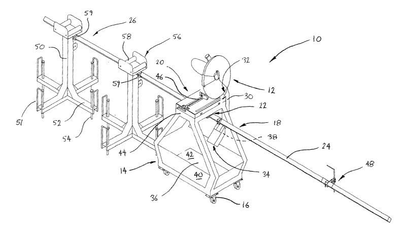
As shown in Figure 1 there is a mobile saw bench
shown generally as 10 which in this embodiment is designed
for cutting elongate workpieces such as elongate open or
closed steel sections. The cut-off saw 12 is a
proprietary product such as a Makita model 2416s 405 mm
cut-off saw, although many other brands and types of saw
can be used in conjunction with the invention.
The mobile saw bench 10 comprises a base structure 14
which is mounted on four castor wheels such as 16. Formed
continuous with the base structure 14 is an intervening
frame structure 18 to which. a benchtop 20 is mounted. The
proprietary saw 12 is appropriately mounted to the
benchtop 20 to permit cutting of a workpiece which is
located thereon.
Importantly, the mobile saw bench l0 further
comprises a universal coupling depicted generally as 22
and shown in Figure 4 in exploded detail. The universal
coupling 22 is in this example mounted to an underside of
CA 02406573 2002-10-17
WO 01/78950 PCT/AU01/00437
- 6 -
the benchtop 20 and is releasably clamped to an elongate
member 24 which in this embodiment is in the form of a
rigid measuring staff. The universal coupling 22 allows
pivotal movement of the benchtop 20 relative to the
measuring staff 24 which is stationary.
In this example the mobile saw bench 10 additionally
comprises a pair of spaced apart stands such as 26 which
are adapted to provide additional support for the elongate
workpiece (not shown). The stands such as 26 are each
releasably clamped to the measuring staff 24 at a required
spacing depending on the length of the workpiece to be
cut. In operation the workpiece is laid across the stands
such as 26 and the benchtop 20 in preparation for cutting.
The benchtop 20 together with the base structure 14 can
then be pivoted whereby the cut-off saw 12 is oriented~at
the required cut-off angle for the workpiece.
The mobile saw bench 10 further comprises an
evacuation system which is operatively coupled to the
benchtop 20 and arranged to extract dust and/or cuttings
discharged from the cut-off saw 12. In this embodiment
the evacuation system includes a chute 30 having inlet and
outlet openings 32 and 34, respectively. The chute 30 is
connected to the benchtop 20 so that the inlet opening 32
is located immediately adjacent the cut-off saw 12 so as
to receive cuttings therefrom. The blade of the saw
creates a draught which is directed toward and drawn
through the chute 30. The trajectory and velocity of the
draught is alone sufficient to "suck" dust and/or cuttings
through the chute 30. The outlet 34 of the chute 30 is
directed toward a tray 36 formed in the base structure 14
of the saw bench 10. Additionally, a filter element 38 is
CA 02406573 2002-10-17
WO 01/78950 PCT/AU01/00437
coupled to the chute 30 adjacent its outlet 34 to filter
cuttings and other solid material discharged from the cut
off saw 12. The filter element 38 in this example
includes a filter medium such as stainless steel swarf
sandwiched between a pair of mesh plates (not shown).
As shown in Figure 2 the saw bench 10 of this
embodiment has the base 14 and intervening frame 18
structures fabricated of angle-section steel. The base
structure 14 is generally rectangular whereas the
intervening frame structure 18 is formed from four (4)
bent legs which extend upwardly from each corner of the
base structure 14. Side wall and floor panels such as 40
and 42, respectively define the tray 36 of the saw bench
10. Otherwise, a benchtop frame 44 of a rectangular
configuration is connected or in this instance welded to
an upper end of the legs of the frame structure 18. The
benchtop frame 44 provides a platform on which the
benchtop 20 is mounted together with the cut-off saw 12
and an appropriate workpiece clamp such as 46.
The chute 30 is in this embodiment welded to the
benchtop frame 44 and a portion of one of the legs of the
frame structure 18. The filter element is detachably
fitted to a lower end of the chute 30 for removal and
cleaning thereof. The chute inlet 32 is flared outwardly
so as to improve the capture of cuttings. Otherwise, the
filter element is depicted by the crossed hatching in
Figure 2.
The rigid measuring staff 24 is formed of a square
hollow section (SHS) which is positioned in a diagonal
orientation. Abutment means such as the sliding element
CA 02406573 2002-10-17
WO 01/78950 PCT/AU01/00437
_ g _
48 is telescopically received on the measuring staff 24
and provides a fixed point against which the workpiece can
abut for cutting of the workpiece at its required length.
The stands 26 of Figure 1 are of identical
construction including a central pedestal 50 from which
four (4) legs such as 52 radially extend. Each of the
legs such as 52 is provided with an adjustable foot
element 54 which in this embodiment takes the form of a
threaded rod. Guard segments 51 protect the user of the
bench from injury or collision with foot elements 54. A
roller platform 56 is mounted to an upper end of the
pedestal 50. The roller platform 56 includes a pair of
rollers such as 58 across which the workpiece is laid in
preparation for cutting. Each of the stands 26 includes a
clamping element 59 having a tubular section of an SHS
profile configured to slidably receive the measuring staff
24. The clamping device 59 is also provided with a
clamping screw which may be in the form of a grub screw or
the like which is threaded through the clamping member and
engages the measuring staff 24 at a corner portion
thereof. Thus, each of the stands 26 can be repositioned
at various positions along the measuring staff 24 and then
clamped thereto. The adjustable feet 54 ensure that the
load of the workpiece is borne by the stand 26 and not the
measuring staff 24. An alternative embodiment of the
workbench and stands is shown in Figure 1A. Like
components of this alternative workbench have the same
part numbers as those components shown in Figure 1. In
Figure 1A the foot guard segments 53 are of a different
type to that shown in Figure 1 (and numbered 51).
Segments 53 confer greater stability to the stand 26
CA 02406573 2002-10-17
WO 01/78950 PCT/AU01/00437
- 9 -
itself while protecting the user of the bench from injury
or collision with the foot elements.
Figure 3 illustrates a variation of the workbench 10
of Figures l and 2. For ease of reference and in order to
avoid repetition like components of this alternative
workbench have been designated with an additional "0".
For example, the base structure has been designated as
140. For clarity purposes the cut-off saw and the
universal coupling have not been illustrated. The
workbench 200 of this particular construction is in
profile substantially square-shaped. The benchtop
includes a peripheral platform 202 which is affixed to the
benchtop frame 440 via threaded bolts such as 204. The
platform 202 includes a recess 206 being adapted to
. receive and locate a universal 405mm cut-off saw. The
discharge chute 300 of this embodiment is clamped rather
than welded to the benchtop frame 440 via a bracket 208.
Otherwise, this alternative mobile sawbench 100 is similar
in construction to the preceding embodiment.
Figure 4 illustrates one example of the universal
coupling 22 of the mobile saw bench 10 of Figures 1 and 2.
The universal coupling includes a fixed element or plate
60 which is welded or otherwise fixed to an underside of
the benchtop frame 44. The universal coupling 22 also
comprises a pivotal element shown generally as 62 which
includes a pivot plate 64 to which a pair of clamp members
such as 66 are connected. The clamp members 66 each
include a relatively short length of a SHS aligned with
one another and connected to the pivot plate 64 via a
connecting web such as 70. The SHS 68 is designed to
slidably receive the measuring staff 24 which is thus
CA 02406573 2002-10-17
WO 01/78950 PCT/AU01/00437
- 10 -
operatively coupled to the workbench 10. This is
illustrated in Figure 5(a). A grub screw 72 is arranged
to screw threadingly engage the SHS 68 and abut or fixedly
grip the measuring staff 24 so that two outer faces of
staff 24 are placed in close frictional contact with two
interior faces of SHS 68 in the manner shown in Figure
5(b) thereby assisting the stabilisation of the apparatus
in use. In further embodiments grub screws can be
inserted vertically upward from the underside of the SHS
to similarly hold the measuring staff in place against two
interior faces of the SHS. A pivot member in the form of
a pivot bolt 74 passes through aligned apertures 76 and 78
formed in the fixed and pivotal plates 60 and 64,
respectively. Thus, the pivot plate 64 together with the
measuring staff 24 pivots about the fixed plate 60 and the
remainder of the mobile bench 10.
In order to further facilitate an understanding of
the invention operation of the mobile saw bench 10 will
now be explained. The general steps involved in cutting
an elongate workpiece are as follows:
(i) the workpiece is placed across the workbench 20 and
adjacent stands such as 26;
(ii) an end of the workpiece is brought into abutment with
the abutment means 48 which is positioned depending on the
length at which the workpiece is to be cut;
(iii) the workbench 10 is pivoted relative to the
measuring staff 24 and the workpiece so that the cut-off
saw 12 is oriented at the required cut-off angle relative
to the workpiece;
(iv) the cut-off saw 12 is brought down to cut the
workpiece at the required angle and length; and
CA 02406573 2002-10-17
WO 01/78950 PCT/AU01/00437
- 11 -
(v) this operation is repeated for this or subsequent
lengths of the workpiece wherein the workbench 10 is
pivoted to the require cut-off angle.
Now that several preferred embodiments of the
invention have been described in some detail it will be
apparent to those skilled in the art that the mobile
workbench and in particular the mobile saw bench has at
least the following advantages:
- workpieces can be cut at a required angle with relative
ease merely by rotating the workbench itself without
repositioning either the workpiece or the cut-off saw~
- the mobile saw bench is particularly effective in
repetitive cutting of elongate workpieces;
- the mobile saw bench provides effective dust and/or
cuttings extraction and collection; and
- the mobile saw bench is relatively safe to use with
minimal trade skills and dexterity.
Those skilled in the art will appreciate that the
invention described herein is susceptible to variations
and modifications other than those specifically described.
For example, the mobile workbench may not be limited to a
saw bench but rather may extend to practically any bench
arrangement to which an elongate member is pivotally
coupled to allow reorientation of the bench relative to
the elongate member. For example, the workbench can be
utilised for varied purposes such as mounting drills, hole
punches or other scoring devices, or for sanding and/or
painting of workpieces where the use of a tool or other
implement mounted to the workbench and angled relative to
the workpiece is required. Furthermore, the mobile bench
CA 02406573 2002-10-17
WO 01/78950 PCT/AU01/00437
- 12 -
need not include the stands as described in the preferred
embodiment. The universal coupling may take a variety of
forms provided it allows pivotal movement of the bench
itself about the elongate member. In further embodiments
the universal coupling can thus be coupled to any portion
of the workbench. In a production line assembly more than
one mobile bench may be pivotally coupled to a common
elongate member. This permits simultaneous cutting of an
elongate workpiece at the required length and cut-off
angles.
All such variations and modifications are to be
considered within the scope of the present invention the
nature of which is to be determined from the foregoing
description.
For the purposes of this specification it is to be
clearly understood that the word "comprising" means
°'including but not limited to°', and that the word
°'comprises" has a corresponding meaning.
It is to be understood that, if any prior art
publication is referred to herein, such,reference does not
constitute an admission that the publication forms a part
of the common general knowledge in the art, in Australia
or any other country.