Note: Descriptions are shown in the official language in which they were submitted.
CA 02406763 2002-11-05
DISPOSABLE CONTAINER FOR LIQUIDS WITH MOLDED LINER
This invention relates to a disposable container for liquids which
includes an inner liquid impermeable liner which can be filled with a liquid
and from
which the liquid can be discharged and an outer shell member formed of a stiff
sheet
material having heat insulating properties.
BACKGROUND OF THE INVENTION
Containers of this type have recently become available primarily for
"take-away" transporting coffee from gourmet coffee shops to a remote location
such
as an office for remote consumption. The conventional coffee cup limits the
amount
which can be carried and is inconvenient to carry a large amount of coffee for
a large
gathering such as at an office meeting.
However the container disclosed herein is not intended to be limited for
use with coffee or other hot beverages and can be used for cold beverages or
other
liquids.
Six patents and applications of Andrews relating to this subject which
are assigned to J&M Coffee Container Company have been located which are US
Patents 5,715,992: 5,909,841; 6,053,401; 6,196,452; 6,290,124 and US Patent
Application 2002/0047040. This discloses a container of this type which has an
inner flexible liner formed from a flat bag with an attached fitment bonded or
welded
to the bag, and an outer stiff cardboard shell which carries the liner. It has
the spout
for filling and pouring from the liner in the front wall of the shell. The
handle is
formed as a folded cardboard handle integral with the outer shell.
CA 02406763 2002-11-05
2
Additional prior art patents 3,233,817 (Casady); 4,815,631 (Eeg) and
3,363,807 (Powell) all show similar arrangements.
A further patent of International Dispensing Corporation which is US
Patents 6,375,040 (Allanson) issued April 2002 relates to a container of this
general
type haing a complex handle arrangement which supports an inner liner bag and
an
outer shell.
Yet further patents in this area also relate to beverage dispensing
containers for gourmet coffee and these are US Patents 6,062,431 (Geshay)
assigned to BIB Pak Inc.; US Patent 6,209,781 (Sylvester) assigned to Liberty
Carton; US Patent 4,781,314 (Schoonover) which relates to a blow molded
container and US Patent 2,954,901 (Winstead) which discloses a rectangular
molded liner with an integral neck which is inserted within a rectangular box
having a
handle on one face. However the neck is not intended for a screw cap and the
inner
liner is molded in two halves and connected together along a diagonal seam.
SUMMARY OF THE INVENTION
It is one object of the present invention to provide an improved
container for liquids of the type having an inner liner and an outer shell.
According to one aspect of the invention there is provided a container
for liquids comprising:
an outer shell member formed of a stiff sheet material having heat
insulating properties which can be erected from a flat storage condition into
an outer
shell defining a base, side walls and a top with a hollow enclosure;
CA 02406763 2002-11-05
3
an inner liquid impermeable fining member arranged to be contained
within the hollow enclosure for containing the liquid such that when inserted
into the
outer shell, the outer shell member and the inner lining member can be
commonly
transported containing the liquid;
a handle exposed on an exterior of the container for manual
transportation and lifting of the container;
at least one opening exposed on an exterior of the container
communicating with an interior of the lining member for communication of the
beverage through the opening, the opening having a neck with a threaded outer
end
for receiving a threaded closure cap thereon;
wherein the inner lining member including the neck and the opening is
an integral molded one-piece body of a plastics material which can be
collapsed
from an erected condition substantially filling the hollow interior to a
collapsed
condition for transport,
The closure cap may be a simple cap which is itself closed or may be a
valve or spigot which can be opened to allow controlled discharge of the
liquid.
Preferably the inner lining member is blow molded which is a technique
which readily and effectively forms a liner as an integral molded body formed
wholly
of plastics material, but other molding or forming methods may be used..
Preferably the inner lining member is semi-rigid so as to maintain an
erected shape when inserted into the outer shell to prevent back-flow of
liquid
through the opening.
CA 02406763 2002-11-05
4
Preferably the inner lining member has a flat base and upstanding side
walls. While the lining member is preferably rectangular in plan other more
complex
polygonal or curvilinear shapes may be used.
Preferably the inner lining member is collapsed by folding.
Preferably the inner lining member is semi-rigid to remain substantially
in erected condition within the outer shell but collapsible under negative
internal
pressure to prevent glugging.
Preferably the handle is integrally molded with the inner liner member
and projects through an opening in the outer shell member.
Preferably the handle forms a hand graspable member defining an
opening between the handle member and a top wall of the inner lining member
with
each end of the handle member attached to the top wall. In this construction,
the
handle member preferably forms a hollow tube since this provides a stiff
connection
of the handle to the liner body. However solid handles can also be readily
molded
and used and may provide a stiff connection and firm support for the liner and
thus
the outer shell.
Preferably tubular handle member is pinched at one end to prevent
contents of the lining member from entering the tubular handle member at that
end.
Preferably the handle is on an inclined surface from one side toward
the top and is parallel to the surface and thus itself inclined downwardly
from the top
since this provides an effective ergonomic support for the container when
lifted for
pouring.
CA 02406763 2002-11-05
Preferably the outer shell has top flaps at front and rear with the flaps
being separate from the sides.
Preferably the outer shell has at least one slot thereon for passage
through the shell of the handle member on inner lining member.
5 Preferably the outer shell has a separate attachment piece defining a
container for accessories which can be attached to the container for
transportation
therewith.
Preferably the separate attachment piece includes a flap which hangs
on an element of the inner liner member projecting through the outer shelf,
that is the
neck or the handle.
Preferably there is provided an optional spigot/tap for attachment to the
opening.
Preferably there is provided an optional tilt bottom formed from a
foldable portion of the outer shell to lift one end of the outer shell for
tilting the inner
liner member toward the opening.
Preferably the inner lining member is translucent for viewing a fill level.
Preferably the inner lining member has a portion exposed through the
outer shell and there are pravided markings for identifying fill level.
Preferably the outer shell has an openable window for viewing the
inner liner and there are provided markings on the outer shell for identifying
fill level.
According to a second separate independent aspect of the invention
there is provided a container for liquids comprising:
CA 02406763 2002-11-05
6
an outer shell member formed of a stiff sheet material having heat
insulating properties which can be erected from a flat storage condition into
an outer
shell defining a base, side walls and a top with a hollow enclosure;
an inner liquid impermeable lining member arranged to be contained
within the hollow enclosure for containing the liquid such that when inserted
into the
outer shell, the outer shell member and the inner lining member can be
commonly
transported containing the liquid;
a handle exposed on an exterior of the container for manual
transportation and lifting of the container;
1 CI at least one opening exposed on an exterior of the container
communicating with an interior of the lining member for communication of the
beverage through the opening, the opening having a neck with a threaded outer
end
for receiving a threaded closure cap thereon;
wherein the handle is integrally molded with the inner liner member
1 b and projects through an opening in the outer shell member.
In this arrangement, preferably the outer shell has at least one slot
thereon for passage through the shell of the handle member on inner lining
member
In this arrangement, preferably the outer shell has top flaps only at
front and rear with the flaps being separate from the sides.
20 According to a third separate independent aspect of the invention there
is provided a container for liquids comprising:
CA 02406763 2002-11-05
7
an outer shell member formed of a stiff sheet material having heat
insulating properties which can be erected from a flat storage condition into
an outer
shell defining a base, side walls and a top with a hollow enclosure;
an inner liquid impermeable lining member arranged to be contained
within the hollow enclosure for containing the liquid such that when inserted
into the
outer shell, the outer shell member and the inner lining member can be
commonly
transported containing the liquid;
a handle exposed on an exterior of the container for manual
transportation and lifting of the container;
1 U at least one opening exposed on an exterior of the container
communicating with an interior of the lining member for communication of the
beverage through the opening, the opening having a neck with a threaded outer
end
for receiving a threaded closure cap thereon;
wherein the inner lining member is blow molded.
In this arrangement, preferably the inner lining member is semi-rigid so
as to maintain an erected shape when inserted into the outer shell to prevent
back-
flow of liquid through the opening.
In this arrangement, preferably the inner lining member is collapsed by
folding.
2a In this arrangement, preferably the inner lining member is semi-rigid to
remain substantially in erected condition within the outer shell but
collapsible under
negative internal pressure to prevent glugging.
CA 02406763 2002-11-05
According to a fourth separate independent aspect of the invention
there is provided a container for liquids comprising:
an outer shell member formed of a stiff sheet material having heat
insulating properties which can be erected from a flat storage condition into
an outer
a shell defining a base, side walls and a top with a hollow enclosure;
an inner liquid impermeable lining member arranged to be contained
within the hollow enclosure for containing the liquid such that when inserted
into the
outer shell, the outer shell member and the inner lining member can be
commonly
transported containing the liquid;
1 Q a handle exposed on an exterior of the container for manual
transportation and lifting of the container;
at least one opening exposed on an exterior of the container
communicating with an interior of the lining member for communication of the
beverage through the opening, the opening having a neck with a threaded outer
end
15 for receiving a threaded closure cap thereon;
wherein there is provided an optional tilt bottom farmed from a foldable
portion of the outer shell to lift one end of the outer shell for tilting the
inner liner
member toward the opening.
According to a fifth separate independent aspect of the invention there
2a is provided a container for liquids comprising:
an outer shelf member formed of a stiff sheet material having heat
insulating properties which can be erected from a flat storage condition into
an outer
shell defining a base, side walls and a top with a hollow enclosure;
CA 02406763 2002-11-05
9
an inner liquid impermeable lining member arranged to be contained
within the hollow enclosure for containing the liquid such that when inserted
into the
outer shell, the outer shell member and the inner lining member can be
commonly
transported containing the liquid;
a handle exposed on an exterior of the container for manual
transportation and lifting of the container;
at least one opening exposed on an exterior of the container
communicating with an interior of the lining member for communication of the
beverage through the opening, the opening having a neck with a threaded outer
end
1 U for receiving a threaded closure cap thereon;
wherein the outer shell has a separate attachment piece defining a
container for accessories which can be attached to the container for
transportation
therewith.
In this arrangement, preferably the separate attachment piece includes
15 a flap which hangs on an element of the inner liner member projecting
through the
outer shell, that is the neck or the handle.
BRIEF DESCRIPTION OF THE DRAWINGS
One embodiment of the invention will now be described in conjunction
with the accompanying drawings in which:
2d Figure 1 is an isometric view from the front and one side of a first
embodiment of container for liquids according to the present invention.
Figure 2 is an isometric view from the rear and the opposite side of the
first embodiment of Figure 1.
CA 02406763 2002-11-05
Figure 3 is a cross sectional view along a center line of the
embodiment of Figure 1.
Figure 4 is an elevational view of the front sheet of the outer shell of
the embodiment of Figure 1.
f> Figure 5 is an elevational view of the rear sheet of the outer shell of the
embodiment of Figure 1.
Figure 6 is a side elevational view of the outer shell of the embodiment
of Figure 1.
Figure 7 is an isometric view of the inner lining member of the
10 embodiment of Figure 1.
Figure 8 is an isometric view of the inner lining member of a second
embodiment.
Figure 9 is an isometric view of a third embodiment.
In the drawings like characters of reference indicate corresponding
parts in the different figures.
DETAILED DESCRIPTION
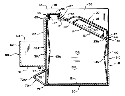
The container disclosed herein includes an inner liner member 10 and
an outer shell 11. The inner liner member 10 is formed to define a semi-rigid
container with a flat base 12, upstanding side walls 13A, 13B and 13C and a
top wall
14. The container is substantially rectangular so that the side walls 13 are
substantially vertical and substantially at right angles. The top wall 14
includes a flat
top portion 15 and an inclined section 16 which extends downwardly from the
top
CA 02406763 2002-11-05
11
portion to the rear one of the side walls indicated at 13C. The lining member
12 has
at the top portion 15 a neck 17 with a screw thread for receiving a threaded
cap 18.
The liner member 10 further has a handle 20 standing up from the
inclined upper portion 16 and defining a tubular handle member 21 which
extends
from the forward end 22 attached to the upper portion 16 to a rearward end 23
also
attached to the upper portion 16 at the rear wall 13C. The handle member is
hollow
and is integral with the liner member. The hollow tubular interior of the
handle
member connects with the hollow interior chamber of the liner member at the
forward end 22. At the rearward end 23 the handle member is pinched as
indicated
at 23A so as to prevent communication of fluids between the hollow interior of
the
finer member and the handle.
The liner member is molded as an integral structure including the neck
17 and the handle 20. This structure can be molded using the technique known
as
blow-molding in which a tubular portion of plastic material in partially
molten form is
fed into a mold which clamps at top and bottom and air is injected into the
interior of
the clamped tubular body so as to expand the plastics material onto the inside
surface of the mold. The mold at the top where it clamps the plastic material
clamps
sufficient material to form the neck and the handle, with generally some
flashing
material which is subsequently cut off. The handle is formed as a tubular
structure
and its interconnection to the interior of the container allows the air
injected into the
interior of the container to also inflate the tubular plastics material at the
handle so
as to form the tubular handle as an integral continuous interior with the
container
without the necessity for separate injection into the handle. Thus air from
the interior
CA 02406763 2002-11-05
12
passes into the handles through the open forward end 22 where the rear end is
pinched to close ofF the handle from the interior of the container.
Blow molding in this manner forms a structure which is semi rigid. This
semi rigid container or liner member has the characteristics that when pulled
into its
rectangular shape it has sufficient strength to stand without collapsing. The
handle
stands firmly upwardly from the upper surface and does not flop to either
side.
However the structure can also be folded by compressing it downwardly so that
the
top surface including the handle and the neck is folded downwardly onto the
bottom
wall 12 with the side walls 13 folding inwardly. In this collapsed condition
the
container can remain folded so that its total volume is reduced to
approximately to
one quarter of the total volume when expanded to its full height. In this way
when
folded the containers can be packaged in relatively small volume for
transportation
and storage. In order to allow the folding, the side walls 13 are slightly
bowed
inwardly at the center as illustrated. The ability to fold and collapse
requires the wall
to be relatively thin and such walls are also therefore flexible so that they
can flex
inwardly when the pressure within the container reduces due to discharge of
liquid.
Thus liquid can be poured out from the container through the neck 17 by
tilting the
container without the necessity for the liquid to be replaced by air due to
the
collapsing of the container inwardly. This avoids the effect known as
"glugging"
where air is required to return into the container through the same opening
thus
interfering with the smooth flow of liquid out from the container when poured.
Thus
the container is semi-rigid and has walls that are sufficiently thin to flex
but the walls
have sufficient strength so that when expanded the walls hold the top surface
away
CA 02406763 2003-04-22
13
from the bottom surface. Thus the container when erected holds the opening at
the
neck 17 away from the base so that any liquid poured into the container when
erected enters the space between the neck and the bottom surface preventing
the
bottom surface from causing backflow of liquid which can occur in a purely
flaccid
liner.
The outer shell 11 is preferably formed of cardboard as a stiff
insulating material. The grade of material selected can vary depending upon
the
amount of insulation required. In one preferred example the grade of cardboard
is of
the type having inner and outer sheets with a corrugated section between the
sheets
thus defining an insulation space between the inner and outer sheets to
improve
insulation value. However simple paper board can be used in a situation where
less
insulation is required. Cardboard has the advantage that it can be folded from
a flat
storage condition to an erect use condition. However, other materials such as
fabric
or Styrofoam (trade mark) can also be used provided that they provide the
necessary properties of sufficient stiffness and sufficient insulation.
The outer shell is formed from a folded and glued box structure using
conventional box forming technology so that the box includes a bottom wall 30
which
is self erecting and self foldable allowing the box to collapse diagonally
with a bottom
folding inwardly between the sides.
The outer shell 11 thus forms a rectangular container with vertical
sides 31 including a front side 31A a rear side 31 C and two sides 31 B. The
sides
31 B in the folded condition collapse together by diagonal collapsing of the
box about
two opposed corners. In the erected condition the base snaps or connects
together
CA 02406763 2002-11-05
14
to form a flat base wall underlying and receiving the flat bottom 12 of the
inner liner
member.
The box or shell is shaped to substantially match the shape of the
inner liner member. Thus there is a front wall 31A which matches the height of
the
front 13A of the liner. There is a rear 31 C matching the height of the rear
13C of the
liner. There is a top section which can be folded so as to lie over the upper
surface
14 of the liner covering the upper surface and generally matching its
inclination.
Thus the sides 31 B include flaps 35 and 36 which can be folded onto
the top portion 15 and the incline portion 16 of the liner. A notch 37 divides
the
portions 35 and 36 so that they can fold about different fold lines. The fold
line of the
flap 35 is thus horizontal whereas the foldline of the flap 3fi is inclined
and co-planar
with the upper surface 16 of the liner. The flaps 35 and 36 are arranged so
that
they, when folded, are spaced from the handle and the neck so as not to
interfere
with those elements when folded onto the top of the liner.
The front wall 13A is shown in Figure 4 and includes a top flap 38
foldable about a fold line 39 which can be folded down onto the top portion
15. The
flap 38 includes an opening 40 shaped to surround the neck 17 allowing the
neck to
project through the opening 40.. The opening 40 has inwardly projecting
elements
which frictionally engage the sides of the neck so as to hold the flap down in
place
onto the neck when the flap is horizontal.
The rear surface is shown in Figure 5 and includes a fold line 42
separating the rear side 31 C from a flap 43. The flap 43 includes two
openings 44
and 45 each for engaging around a neck part of the handle member 20 with a
slot 46
CA 02406763 2002-11-05
interconnecting the openings so that the slot can pass over the handle into
the
opening between the handle and the upper surface 16.
Thus in operation, the shell can be stored in a folded condition with the
sides flat and the fold lines formed by scoring or compression of the board
material.
The shell can then be erected by folding out the base so that the sides are
moved to
their positions at the sides of the rectangular shape and upstanding from the
horizontal base 30. In this erected condition, the liner member can be erected
from
its collapsed condition and inserted into the interior of the outer shell.
With the liner
in position, the side flaps are folded inwardly and then the flap 38 folded
down over
10 the neck and the flap 43 folded down over the handle so as to trap the
flaps 35 and
36 underneath the flaps 38 and 43 to enclose the inner liner member within a
closed
outer shell. In this position, the handle projects through the outer shell so
that the
whole container can be lifted by the handle 20 which is integral with the
inner liner.
Also the neck 17 projects through the outer shell so that the cap 18 can be
applied.
15 Within the outer shell, the inner liner is erected or extended so that its
bottom
surface 12 lies against the bottom wall 30.
This erected and assembled condition can be readily and quickly
achieved by removing the collapsed pieces from a storage container and quickly
assembling them manually to provide the assembled container.
On the side 31 B as shown in Figure 6 is provided a window 47 formed
in the board material with a hinge line 48 on one side allowing the window to
be
opened to expose the liner within the shell. The liner is formed from a
translucent
plastics material so that a level of the liquid within the liner can be
observed up to a
CA 02406763 2002-11-05
16
required fill line. Markings 50 can be provided on the outer shell at the
window so
that various fill levels can be provided marking pre-determined quantities of
liquid
within the inner liner.
In use with the container in the erected and assembled condition, the
cap 18 can be removed and liquid poured into the hollow interior of the inner
liner.
Because the inner liner is in an erected condition, there is no splash back or
flow
back of the liquid since it pours to the bottom of the inner liner thus
readily being
received within the inner liner up to a filled condition. When filled up to
the required
fill level as indicated by the markings 50, the window can be closed and the
cap 18
reapplied.
This arrangement has the following advantages:
a) The handle is integral on the inner liner so that the structure is
more stable and the handle is more rigidly attached to the container as a
whole as
opposed to an arrangement in which the handle is merely a cardboard flap.
b) The neck is an integral part of the inner liner rather than an
adhesively or otherwise attached separate piece.
c) The inner liner is sufficiently structured so that it is held and
maintained open thus readily receiving the material when poured.
d) The integral liner has sufficient structural stability so that it can
readily pass a "drop test" to avoid breakage and release of the contents.
e) The top flaps are of a simple construction simply folding over
the handle and the neck so that they can be readily assembled.
CA 02406763 2003-04-22
17
f) When attached to the neck and the handle, the outer shell is
stable and remains readily in place.
g) The handle is on the same incline as the inclined top surface so
that it makes holding and pouring through the neck more simple.
h) There is a single opening in the inner liner so that the
construction is very simple and can be readily sealed.
i) The fill level can be readily viewed.
j) The inner liner is sufficiently flexible so that the liquid can be
poured while the liner collapses sufficiently to avoid glugging.
k) The liner member is formed by molding wholly from a suitable
plastics material without the necessity for a laminate layer of foil. Such
foils are
undesirable since they prevent recycling of the liner member and since they
prevent
heating of the container by microwave energy.
I) The molded liner member also allows cleaning and reuse of the
container since whole of the interior of the liner can be readily washed
through the
opening at the neck.
m) The arrangement of the handle which is integral with the liner
member provides more security for lifting hot liquids and provides an improved
ergonomics of handling both for filling and pouring through the single opening
at the
neck. The location and inclination of the handle keeps the hand away from the
hot
steam at the neck and allows the user to readily tilt the container for
pouring without
unsuitable twisting of the wrist.
CA 02406763 2002-11-05
1$
n) The use of a single opening for filling and pouring forms a
simple and secure structure for handling hot liquids without danger of
spillage. The
location of the single opening allows the dispensing of the liquid by pouring
or by
draining using the optional spigot.
A first optional arrangement provides a container or caddy for
accessories including cups and mixing materials such as sugar and cream. This
container comprises a formed rectangular box 60 foldable in the same
conventional
manner as the main shell to define a base 61 and upstanding sides 62. One of
the
sides 62A has a top flap portion 63 which extends beyond an open mouth 64 of
the
box upwardly along the front face 31A to a fold line 65 at which the flap can
be
folded along the top of the flap 38 to engage around the neck 17. Thus the box
or
container 60 is hung off the neck along the front face and allows the
transport of the
accessories in a readily attached manner when the container is carried by the
handle. The support of the accessories on the front avoids any interference
with the
handle and provides a reasonable balance of the weight of the structure. The
engagement of the flap 66 around the neck provides a suitable attachment which
allows sufficient weight to be carried within the container as required for
the quantity
of liquid within the container.
The accessory box 60 can be attached onto the container at any other
suitable location suspended off the neck or the handle as required.
A second option is shown in Figure 3 and 4 and comprises a support
Leg 70 which can be moved to an erected condition shown in Figure 3. The leg
70 is
intended to be used with the accessory box removed and in an arrangement using
CA 02406763 2002-11-05
19
an optional spigot in replacement far the cap 18. such spigots are well known
and
commercially available and can be applied while the opening 17 is upstanding
as a
replacement for or as an alternative for the simple closure cap. The spigot
has a
valve allowing liquid to be poured or dispensed. When the spigot is applied,
the
container can be rotated so that the wall 31 A lies on a support surface such
as a
table. The leg 70 thus raises the base 30 upwardly so that all of the liquid
moves to
the opening neck 17 and the spigot (not shown) allowing all of the liquid to
be
dispensed without the necessity for lifting the container and pouring the
liquid.
The leg 70 is die cut from the front face 31A so that it is provided as an
integral part of the outer shell rather than as a separate piece. Different
shapes of
foldable leg can be provided as will be well know to one skilled in the art.
However
one preferred shape is shown in the drawings and provides a hinge line 71 at
the
bottom. The leg has a central hinge line 72 halfway across the leg so that it
can be
folded at that hinge line to form an apex 72A which sits on the support
surface when
the container is rotated to the dispensing position. At the top of the leg 70
is
provided a flap portion 73 which tucks in between two notches 74 when the leg
is
erected. Thus in the erection operation, the die cut leg is broken away from
the front
face and pulled outwardly about the hinge line 71 so that it forms a flap
projecting
outwardly from the front face. The flap is then bent around the hinge line 72
so that
the flap portion 73 projects backwardly toward the surface 31A. The flap 73 is
then
tucked back into the hole left by the removal of the flap at the notches 74.
Two
wings 75 on the leg engage against the sides of the notches 74 so as to hold
the leg
in place with the apex projecting outwardly from the surface 31A.
CA 02406763 2002-11-05
as
Alternative shapes ofi the structure are shown in Figures 8 and 9. Thus
the inner liner member and its associated shell may not necessarily be
rectangular
but other more complex polygonal shapes can be used, In Figure 9, the spigot
indicated at 80 as shown is attached to the neck 17.
In Figure 8, the handle is shown on an inclined surface of the inner
liner and this arrangement is preferred since the handle can then be molded as
part
of the same tubular structure in the blow molding process. However an
arrangement
less favorable is shown in Figure 9 in which the handle projects outwardly
from the
side of the inner container as indicated at 82, In this arrangement the top
surface is
horizontal.
Since various modifications can be made in my invention as herein
above described, and many apparently widely different embodiments of same made
within the spirit and scope of the claims without departing from such spirit
and
scope, it is intended that all matter contained in the accompanying
specification shall
be interpreted as illustrative only and not in a limiting sense.