Note: Descriptions are shown in the official language in which they were submitted.
CA 02407624 2002-10-25
WO 01/81960 PCT/US01/13172
Hollow Cavity Light Guide for the Distribution of Collimated Light to
a Liquid Crystal Display
BACKGROUND OF THE INVENTION
Technical Field
This invention relates to uniformly distributing collimated light for
information
display, illumination, and direct lighting applications.
Background Art
It has long been a goal to develop large flat displays such as large screen
television sets for consumer use. The expected performance for such displays
is that
they meet or exceed the performance of the well-known cathode ray tube (CRT)
television (TV) display. This expected performance can include, for example, a
wide
viewing angle - with the present day CRT technology, a viewer can sit almost
anywhere
relative to the TV screen and experience essentially the same picture quality.
This CRT
quality level is typically inherent in both projection and emissive, such as
plasma
display, technologies.
Wall-mounted TV sets with large area plasma displays have been introduced into
the consumer market. These plasma displays are relatively thin, typically less
than five
(5) inches (12.7 cm) thick, and have CRT-like viewing angles. However, large
are
plasma displays are currently too expensive for large-scale consumer use and
tend to be
of lower resolution than competing display technologies.
Projection displays require an unimpeded path between the projector and a
screen. Backscreen projection displays typically include a large enclosure
containing the
projector, relay optics and a translucent screen. Because of these
limitations, both types
of projection displays are considered undesirable for large-scale consumer
use.
-1-
CA 02407624 2002-10-25
WO 01/81960 PCT/US01/13172
Direct view liquid crystal displays, which are reasonably inexpensive to
manufacture, are beginning to be introduced into the consumer TV set market.
However,
a typical liquid crystal display (LCD), such as a twisted-nematic LCD (TN-LCD)
found
in a typical laptop computer cannot normally provide the wide viewing angle
expected
by the consumer for a TV set. Several methods have been employed to widen the
viewing angle of an LCD display and to also limit the overall thickness of an
enclosure
so that such a display could be used as a wall-mounted TV.
A typical approach to lighting an LCD display is to position a solid edge-
illuminated light guide behind the LCD display. Collimation is known to
improve the
viewing angle of an LCD display when used in combination with a viewing screen
applied to the output polarizer of the LCD display. It is also important to
minimize
surface reflections from the combination of viewing screen and LCD in order to
provide
sufficient readability in ambient lighting conditions. Previous attempts to
minimize such
reflections include the use of neutral density filters, triple notch filters,
and circular
polarizers.
There are several disadvantages associated with the use of solid edge-
illuminated
light guides as known in the art including the weight of such light guides and
a decrease
in light transmittance due to bulk material effects such as absorption and
haze. For
example, a solid glass light guide that would provide a 40-inch (101.6 cm)
diagonal
display the same luminance that a 10.4-inch (26.4 cm) diagonal display light
guide
would receive from a 6-millimeter thick solid glass light guide weighing 0.5
lb. (0.23
kg), would be 23-millimeter thick and weigh approximately 30 lb. (13.6 kg).
Some
optical glass exhibits light absorption losses as low as 0.002% /cm, while
many optical
plastics are closer to 0.10% /cm. It is worthy to note that this light
absorption loss is not
constant with wavelength, and therefore there is a corresponding change in the
spectrum
of the output light for a solid light guide device.
Previous attempts at both hollow and semi-hollow edge-illuminated collimated
light guides have suffered from a non-uniform light output. Attempts to
correct this non-
uniformity including curving the extraction surface, employing very long
extraction
-2-
CA 02407624 2002-10-25
WO 01/81960 PCT/US01/13172
lengths, and tilting the centerline of collimated light source away from a
light guide exit
surface have met with varying degrees of success.
There is a need for an efficient and compact hollow edge-illuminated light
guide
for the distribution of collimated light to a liquid crystal display (LCD)
that provides a
uniform light output.
SUMMARY OF THE INVENTION
Disclosure of Invention
My invention comprises a method and apparatus for distributing collimated
light
and may be employed in lighting applications to enhance viewing angles of a
wide angle
Liquid Crystal Display (LCD). It can also be employed to distribute collimated
light for
other direct-lighting applications. More specifically, my invention is a light
guide
comprising a unique configuration of a hollow cavity surrounded by various
optical films
that receives collimated light through an entrance aperture and transmits the
light
uniformly from an exit aperture that is orthogonal to the entrance aperture.
Advantageously the input light is both collimated and homogenized.
A significant advantage to the inventive hollow light guide is that any size
guide
can be assembled using the same microstructured parts and specular reflectors,
so long as
the collimation elements, such as morphing elements are the same.
BRIEF DESCRIPTION OF THE SEVERAL VIEWS OF THE DRAWING
Brief Description of Drawings
FIG. I depicts a single-edge-coupled, polarized, hollow light guide in
accordance
with the present invention and detailing the extraction method for an upper
light lobe.
FIG. 2 depicts the hollow light guide of FIG. 2, detailing the extraction
method
for a lower light lobe.
-3-
CA 02407624 2002-10-25
WO 01/81960 PCT/US01/13172
FIG. 3 shows the geometric relationship between the thickness and length of
the
hollow light guide of FIGS. 1 and 2.
FIG. 4 shows the results of ray-trace modeling for the extraction mechanism of
FIGS. 1 and 2.
DETAILED DESCRIPTION OF THE INVENTION
Mode(s) for Carrying Out the Invention
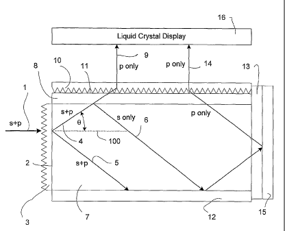
Referring to FIG. 1, the principle of operation of an LCD display 16 is to
preferentially pass light that has been linearly polarized along a predefined
axis. My
invention accepts collimated homogenized light containing both s-polarized and
p-
1o polarized components through an entrance aperture 2 as shown in FIG. 1 and
outputs
light containing only a p-polarized component through exit aperture 11. If the
axis of the
p-polarized component is not aligned with that of the LCD display 16, a
retarder,
available for example from NittoDenko or International Polarizer, can be
inserted
between the exit aperture I1 and the LCD display 16 in order to improve
efficient
transfer of light therebetween. Phase correction members can be employed to
further
enhance contrast.
The hollow light guide, according to my invention, is formed by enclosing a
hollow cavity 7 with optical films. The hollow cavity 7 is configured as a
parallelepiped
that includes a first set of parallel faces consisting of an entrance aperture
2 and an
opposing distal edge, a second set of parallel faces consisting of a bottom
edge and an
exit aperture 11, and a third set of parallel faces defining the sides (not
shown). A
reference plane 100, extending through and perpendicular to the entrance
aperture 2 and
parallel the exit aperture 11 is illustrated for reference purposes in FIGS. 1
and 2. One
feature of my invention is that the exit aperture 11 is orthogonal to the
entrance aperture
2 and the third set of parallel faces.
The entrance aperture 2 is covered by a beam splitting structure 3; such as a
prismatic array film which can be similar in shape to Brightness Enhancement
Film
-4-
CA 02407624 2002-10-25
WO 01/81960 PCT/US01/13172
(BEF) manufactured by the 3M Corporation. In an embodiment of my invention
where
the beam splitting structure 3 comprises a prismatic array film, a planar side
of this
prismatic array film faces the hollow cavity 7. The beam splitting structure 3
is
configured to symmetrically split an incoming beam of homogenized collimated
light 1
into an upper beam lobe 4 and a lower beam lobe 5, where the upper and lower
beam
lobes diverge in opposing directions on either side of the reference plane 100
by an angle
0. In is one aspect of my invention that the magnitude of the angle 0 formed
between the
upper beam lobe 4 and the reference plane 100 is of the same magnitude as the
angle 0
formed between the reference plane 100 and the lower beam lobe 5.
The distal edge of the hollow cavity 7 is formed by a retarder 13 disposed
upon a
first specular reflector 15. The bottom edge of the hollow cavity 7 is formed
by a second
specular reflector 12. The third set of parallel faces (not shown) are each
also formed by
specular reflectors.
The exit aperture 11 is covered by a reflective polarizer 8 adjacent to a beam
directing structure 10 including coarse prismatic features, such as a
prismatic array film.
In an embodiment of my invention where the beam directing structure 10
comprises a
prismatic array film, a planar side of this prismatic array film faces away
from the hollow
cavity 7. In order to preserve the light polarization state; the beam
directing structure 10
should be manufactured in such a fashion and of such polymers as to
substantially reduce
any birefringence properties. Suitable materials are available from the
eyeglass industry,
such as CR-39 allyl diglycol carbonate resin from PPG Industries, and.the
compact disk
industry, such as Plexiglas VOD-100 acrylic molding resin from ATOFINA
Chemicals,
Inc.
The reflective polarizer 8 may be constructed out of suitable materials such
as
multi-layer polymeric films, grazing incidence holograms, and cholesteric
liquid crystal
films.
In order to maintain light collimation within hollow cavity 7, it is necessary
to
maintain the orthogonality and flatness of the bounding optical surfaces.
Accordingly,
-5-
CA 02407624 2002-10-25
WO 01/81960 PCT/US01/13172
these optical film surfaces require structural supporting members. The
surfaces that do
not transmit light can be supported by glass or plastic sheet stock, further
stiffened by
metallic and/or honeycomb structures. The surfaces that transmit light, such
as exit
aperture 11 can be supported by small transparent and non-birefringent post-
like
elements (not shown). These transparent post-like elements are small enough in
cross
sectional area that they should prove invisible once the output beam reaches
the LCD
display 16. In another embodiment of my invention, the supporting post-like
elements
are light absorbing instead of being transparent.
In a preferred embodiment, a source of unpolarized light from an optical
conduit
is collimated by close-packed high aspect ratio non-imaging optical elements
feeding
into the rectangular edge of a hollow light guide. Such non-imaging optical
elements
could comprise an array structure built up from a plurality of round-to-square
morphing
elements with adjacent planar sides in optical contact, or alternatively an
array of hollow
triangular elements enclosed by upper and lower mirrored plates. Both array
structures
are advantageously designed to ensure a uniform light output. Optionally,
these
structures can be followed by prisms and spacers that are optically bonded
using a low
refractive index adhesive, to allow for various packaging constraints while
still
maintaining uniformity.
Advantageously, a hollow light guide according to my invention can be designed
to limit several sources of light decollimation, including but not limited to:
= Surface microroughness
= Edge-rounding of the microstructured features induced by manufacturing
processes
= Material bulk effects, such as scatter due to inclusions, refractive index
changes (e.g. air bubbles), and the like
= Material warp, bend, and twist
-6-
CA 02407624 2002-10-25
WO 01/81960 PCT/US01/13172
Referring to Figures 1 and 2, the optical light guide according to my
invention
operates in the following manner. An unpolarized collimated light beam 1 is
received at
the entrance aperture 2, which is covered by a beam splitting structure 3,
such as a
prismatic array film. Interactions between the unpolarized collimated light
beam 1 and
the beam splitting structure 3 act to symmetrically split the unpolarized
collimated light
beam 1 into an upper beam lobe 4 and a lower beam lobe 5, where each beam lobe
contains both s-polarized and p-polarized light.
The upper beam lobe 4 is directed through the hollow cavity 7 and caused to
impinge upon the reflective polarizer 8. Interactions between the upper beam
lobe 4 and
the reflective polarizer 8 act to separate the upper beam lobe 4 into an s-
polarized upper
beam 6 and a p-polarized upper beam 9.
The p-polarized upper beam 9 exits through the reflective polarizer 8 into the
beam directing structure 10 including coarse prismatic features, which covers
the exit
aperture 11. Interactions between the p-polarized upper beam 9 and the beam
directing
structure 10 including coarse prismatic features act to straighten the p-
polarized upper
beam 9 as it passes therethrough and exits through the exit aperture 11.
The s-polarized upper beam 6 is reflected back through the hollow cavity 7,
caused to impinge upon the second specular reflector 12, and thereby being
reflected into
the retarder 13. Interactions between the s-polarized upper beam 6 and the
retarder 13
act to convert the s-polarized upper beam 6 into a p-polarized converted upper
beam 14
as it passes therethrough. The resultant p-polarized converted upper beam 14
is reflected
from the first specular reflector 15 back through the hollow cavity 7 and
caused to
impinge upon the reflective polarizer 8. The p-polarized converted upper beam
14 also
exits through the reflective polarizer 8 into the beam directing structure 10
including
coarse prismatic features, which covers the exit aperture 11. Interactions
between the p-
polarized converted upper beam 14 and the beam directing structure 10
including coarse
prismatic features act to straighten the p-polarized converted upper beam 14
as it passes
therethrough and exits through the exit aperture 11.
-7-
CA 02407624 2002-10-25
WO 01/81960 PCT/US01/13172
The lower light beam lobe 5 is directed through the hollow cavity 7 and caused
to
impinge upon the second specular reflector 12. The lower light beam lobe 5,
which
contains both s-polarized and p-polarized light must be precluded from
impinging upon
the retarder 13 disposed on the distal edge of the hollow cavity 7.
The lower beam lobe 5 is reflected from the second specular reflector 12 back
through the hollow cavity 7 and caused to impinge upon the reflective
polarizer 8, as
seen in Figure 2. Interactions between the lower beam lobe 5 and the
reflective polarizer
8 act to separate the lower beam lobe 5 into an s-polarized lower beam 18 and
a p-
polarized lower beam 17.
The p-polarized lower beam 17 also exits through the reflective polarizer 8
into
the beam directing structure 10, which covers the exit aperture 11.
Interactions between
the p-polarized lower beam 17 and the beam directing structure 10 act to
straighten the p-
polarized lower beam as it passes therethrough and exits through the exit
aperture 11.
The s-polarized lower beam 18 is reflected back through the hollow cavity 7,
caused to impinge upon the second specular reflector 12, and thereby being
reflected into
the retarder 13. Interactions between the s-polarized lower beam 18 and the
retarder 13
act to convert the s-polarized lower beam 18 into a p-polarized converted
lower beam 19
as it passes therethrough. The resultant p-polarized converted lower beam 19
is reflected
from the first specular reflector 15 back through the hollow cavity 7, further
reflected
from the specular reflector 12, and finally caused to impinge upon the
reflective polarizer
8. The p-polarized converted lower beam 19 also exits through the reflective
polarizer 8
into the beam directing structure 10, which covers exit aperture 11.
Interactions between
the p-polarized converted lower beam 19 and the beam directing structure 10
act to
straighten the p-polarized converted lower beam 19 as it passes therethrough
and exits
through the exit aperture 11.
It is a feature of my invention that substantially all of the input
unpolarized
collimated light beam 1 is converted to p-polarized light and exits through
exit aperture
-8-
CA 02407624 2002-10-25
WO 01/81960 PCT/US01/13172
11 with substantially none of input unpolarized collimated light beam 1 being
recycled
back through entrance aperture 2.
Figure 3 shows some of the design considerations that are associated with the
particular embodiment of my invention described above. As shown in Figures 1
and 2,
the hollow cavity 7 is configured as a parallelepiped with the entrance
aperture 2
orthogonal to the exit aperture 11. Referring to Figure 3, the light guide
thickness 't'
301, of the hollow cavity 7, is dependent on both luminance, as limited by
entendue
considerations, and mechanical packaging constraints. The light guide length
'L' 302, of
the hollow cavity 7, is determined by the area to be illuminated, such as an
LCD display.
The input beam lobe angle '0' 303, measured from an axis line perpendicular to
said
entrance aperture 2, also shown as a dashed line on Figures 1 and Figure 2, is
selected to
provide output beam uniformity. The input beam lobe angle '0' 303 is
restricted to
certain angles due to the inherent limitations in the beam splitting structure
3 and the
beam directing structure 10.
Referring to Figures 1, 2, and 3, it is an aspect of my invention that the
combination of t, L, and 0, be selected such that the lower light beam lobe 5,
which
contains both s-polarized and p-polarized light, is precluded from being
reflected into the
retarder 13 without first being separated into p-polarized and s-polarized
component
beams, for example by reflective polarizer 8.
To practice the particular embodiment of my invention described above, input
beam divergence and microstructural element geometry will require adjustments
to t and
0, where Tan 0 = L, to ensure uniformity of the output the p-polarized upper
beam 9, p-
polarized converted upper beam 14, p-polarized lower beam 17, and p-polarized
converted lower beam 19 as well as overall light guide efficiency.
Mathematical analysis
and ray tracing methods that are known in the art can be used to determine
these
adjustments.
-9-
CA 02407624 2002-10-25
WO 01/81960 PCT/US01/13172
Referring next to FIG. 4, the results of ray-trace modeling for the extraction
mechanism of FIGS. 1 and 2 is shown. Surface detail 402 shows an example prism
element, greatly enlarged for illustrative purposes, with a refractive index
of 1.58 and an
apical angle of about 105 , which can form a portion of the surface of the
beam splitting
structure 3, comprising a prismatic array film, in accordance with one
illustrative
embodiment of my invention. Surface detail 401 shows an example prism element,
greatly enlarged for illustrative purposes, with a refractive index of 1.58
and an apical
angle of about 63 , which can comprise a portion of the surface of the beam
directing
structure 10, comprising a prismatic array film, in accordance with one
illustrative
embodiment of my invention. The reflective polarizer 8, adjacent to the beam
directing
structure 10, as shown in FIG. 1 is advantageously a multi-layer polymeric
film, grazing
incidence hologram, or cholesteric liquid crystal film. The individual ray
traces 403 are
shown interacting with the beam splitting structure 3, beam directing
structure 10, first
specular reflector 15, and the second specular reflector 12.
Referring to both FIGS. 1 and 4, the unpolarized collimated light beam 1, for
example having a source input convergence half-angle of 7 is shown being
split by the
beam splitting structure 3 which includes a surface detail 402 further
including a prism
element with an apical angle of about 105 . Interactions between the
unpolarized
collimated light beam 1 and the beam splitting structure 3 act to split the
unpolarized
collimated light beam 1 into an upper beam lobe 4 as previously described.
Interactions
between the upper beam lobe 4 and the reflective polarizer 8, which includes a
surface
detail 401 further including a prism element with an apical angle of about 63
, act to
separate the upper beam lobe 4 into s-polarized and p-polarized beams as
previously
described.
Referring to both FIGS. 2 and 4, interactions between the lower beam lobe 5
and
the reflective polarizer 8, which includes a surface detail 401 further
including a prism
element with an apical angle of about 63 , act to separate the lower beam lobe
5 into s-
polarized and p-polarized beams as previously described.
-10-
CA 02407624 2002-10-25
WO 01/81960 PCT/US01/13172
In alternate embodiments of my invention, the hollow cavity 7 may be a vacuum
chamber, or filled with air, dry nitrogen, or an inert gas.
In a preferred embodiment of the invention, each of the p-polarized upper beam
9, p-polarized converted upper beam 14, p-polarized lower beam 17, and p-
polarized
converted lower beam 19 are directed toward the liquid crystal display 16.
In another preferred embodiment of my invention, light is transmitted from an
optical conduit, such as an optical fiber and collimated by an array of
tapered non-
imaging optical collimation elements before entering the entrance aperture 2.
Advantageously, the collimation elements have a square cross section at their
output,
io allowing adjacent elements to be easily abutted, and also homogenize the
light before it
enters the entrance aperture 2.
Alternate embodiments may be devised without departing from the spirit or the
scope of the invention.
-11-