Note: Descriptions are shown in the official language in which they were submitted.
CA 02407647 2002-10-28
WO 01/83890 PCT/GB01/01869
- 1 -
Lattice Panel Structures
This invention relates to lattice panel structures,
such as bridges of the "Bailey" type. The invention is
particularly concerned with a modular lattice panel
system.
In a typical "Bailey" bridge construction there is
provided a main girder at each side of the bridge,
transoms extending between the girders and a deck
supported on the transoms. The girders are formed from
prefabricated lattice panels of steel which are joined
together longitudinally. Two or more sets of the lattice
panels may be secured together in the vertical direction
so as to provide the required depth of girder, and to
this end the panels are generally of a rectangular
configuration. A common type of lattice panel consists
of upper and lower longitudinally extending chords which
are joined together by a lattice of web members. These
will generally include vertically extending web members
and angled web members which may for example extend at
an angle of about 45 to the chords. Various panel
configurations are disclosed in GB-A-2 251 018, for
example.
To join the panels together in end to end
relationship to provide the required length of girder,
pin and aperture joints are usually employed to ensure
speed and simplicity of assembly on site. One end of
each chord will be formed with a female portion and one
with a male portion. These are mated when the panels are
to be joined together and then a transverse pin is
inserted through apertures in the portions.
Bridges of the above type are often used as
temporary structures, for example to replace bridges
destroyed by floods, earthquakes or acts of war. They
are supplied as prefabricated components which are
CA 02407647 2002-10-28
WO 01/83890 PCT/GB01/01869
- 2 -
assembled on site. In one common method of construction,
the bridge girders are assembled on one side of the gap
to be bridged, such as a river or ravine, and pushed out
and over to the other side.
In a conventional system, the lattice panels are
provided as completely prefabricated units with the web
members welded to the chords. Typically, a standard
length prefabricated panel will be available, and the
designer of a bridge will use the appropriate number of
these, to be joined end to end, for the bridge.
A significant advantage of using prefabricated
panels is that bridges can be constructed quickly with
the minimum of on - site fabrication. However, there are
design constraints due to the limited number of panel
configurations available. It is also necessary to
restrict the length of the prefabricated panels used as
the basic units, so thatthere is sufficient flexibility
to achieve a desired length by joining a number
together. However, the joins between adjacent panels can
be expensive, particularly if they are of the pin joint
variety requiring forgings. The more panel units are
required to span a given length, the more joins are
required. a further problem is that prefabricated panels
are bulky to transport.
An object of the present invention is to provide a
modular system for constructing lattice panels which
provides greater flexibility but which does not increase
to an undesirable level the time spent on site to
construct a bridge.
Viewed from one aspect the present invention
provides a modular system for the construction of a
lattice panel for a structure, comprising first and
second elongate chord members and a plurality of web
members for attachment to the chord members so as to
hold them apart transversely, wherein each web member
comprises three legs forming a triangle, a first leg
being adapted to extend perpendicularly between the
CA 02407647 2002-10-28
WO 01/83890 PCT/GB01/01869
- 3 -
chord members, and second and third legs being joined to
each other and to adjacent the ends of the first leg,
and wherein there are provided the following means for
interlocking each web member to the chord members and to
like web members:
first interlocking means adjacent one end of the
first leg to interlock with corresponding second
interlocking means provided at intervals along the first
chord member;
third interlocking means adjacent the other.end of
the first leg to interlock with corresponding fourth
interlocking means provided at intervals along the
second chord member;
fifth interlocking means adjacent the join between
the second and third legs; and
sixth interlocking means intermediate the ends of
the first leg;
the arrangement being such that the fifth
interlocking means of one web member is adapted to
interlock with the sixth interlocking means of an
adjacent like web member.
Thus, in use a lattice panel can be constructed
with upper and lower chord members and a lattice of web
members providing vertical legs extending between and
connected to the chord members, and inclined legs which
are joined to the vertical legs of adjacent web members.
Such an arrangement provides a strong lattice panel.
It is a simple matter to provide lattice panels of
desired lengths, by selecting chord members of
appropriate lengths and a corresponding number of web
members. To cover a certain distance it may be possible
to use a single panel constructed from the modular
components with long chord members, rather than two or
more standard lattice panels joined end to end. From a
manufacturing point of view, it is preferable to
fabricate and store the modular components capable of
forming lattice panels of various lengths, rather than
CA 02407647 2002-10-28
WO 01/83890 PCT/GB01/01869
- 4 -
complete lattice panels of various lengths. Furthermore,
the conventional joints between lattice panels,
typically involving forged components, are expensive.
The ability to construct longer panels, simply and from
prefabricated components, reduces the total number of
panels required for a particular job and thus the number
of expensive joints. The end user will also have fewer
inter-panel joints to assemble if longer panels can be
used.
The fabrication of the lattice panels may be
carried out at a manufacturing site once an order is
received, for shipment to a place of use. Alternatively,
the modules may be shipped to the end user for assembly
into panels on-site. This may be preferable from a
shipping point of view. It may also be possible for the
chord members to be manufactured locally if their design
is simple enough, this being discussed below, so that
only the web members have to be shipped.
It is known for the upper chords of lattice panels
to be joined by simple compression joints, for example
using abutting flanges and threaded fasteners. These
chords can be made on site relatively easily. The lower
chord joints are in tension and conventionally they have
been in the form of pin joints which provide the
required tensile strength whilst being relatively quick
and simple to assemble. The pin joints are expensive,
forged items, and it is less feasible to manufacture the
lower chords on site. In accordance with the present
invention, however, it is practical to use longer chords
and fewer chord joints. For example, a panel in
accordance with the invention may be between three and
four times the length of a conventional panel. It is
thus feasible to use alternative chord joints for the
lower chords, which are cheaper and easier to
manufacture even though it may take longer to join two
chords. Thus, in one proposed arrangement the lower
chord joints are provided by splice plates and several
CA 02407647 2002-10-28
WO 01/83890 PCT/GB01/01869
- 5 -
threaded fasteners. An advantage of such a simple joint
is that the chords only need to be provided with
apertures for the fasteners and it is a more practical
proposition for the chords to be made on site.
There may be a number of different chords that can
be used. For example, a stronger chord could be provided
if required. This could be only at suitable positions,
such as at the centre of a bridge span. This avoids the
need to take a standard lattice panel and add a
reinforcing chord to it. It is also possible to
introduce camber by using chords of different lengths at
the top and bottom of a panel. A longer upper chord will
introduce positive camber, resisting the tendency of a
bridge to sag in the middle.
The interlocking means should be such that the
modules can be assembled in the required orientation and
also provide for the transfer of forces. In a preferred
embodiment, where two interlocking means interlock,
there is provided a male spigot on one member and a
matching female recess, for example in the form of an
aperture, on the other member. For any interlock there
may be one, two, three, four or more such spigots and
matching recesses. There may also be fasteners such as
threaded bolts secured by nuts to clamp the components
together, although the primary purpose of such threaded
fasteners will generally not be to transfer forces. In
one preferred form, the first and third interlocking
means, at opposite ends of the first leg of the web
member, comprise spigots. This means that the chords
only need to have apertures to constitute the
corresponding second and fourth interlocking means. This
again helps in simplifying the design of the chords,
reducing manufacturing costs and also making it feasible
for them to be manufactured on site. However, if
desired, reinforcing components could be attached to the
chords to receive the spigots.
The fifth and sixth interlocking means, which are
CA 02407647 2002-10-28
WO 01/83890 PCT/GB01/01869
- 6 -
provided to join the web members together, preferably
also comprise spigots and recesses. For ease of
manufacture, at least one of the interlocking means may
be provided on a cast member.
In general, the philosophy behind the preferred
implementation of the invention is to keep the chords
and their joints as simple as possible, and to
concentrate the more complex and / or expensive
structures on the web members. The design of the modular
web member may lend itself to robotic construction,
something which has not been considered feasible with
the construction of entire lattice panels from
individual components.
A web member may be in the form of an isosceles
triangle, with the second and third legs of equal
length. In such an arrangement, the sixth interlocking
means will be arranged on the mid point of the first leg
and the fifth interlocking means, where the second and
third legs meet, will be aligned with this. In one
preferred arrangement, the angle that each of the second
and third legs makes with the first legs is about 450,
so that the width of a web member is about one half of
its height, i.e. the extent of the first leg which
extends perpendicularly between the chord members. By
using a web member with a longer first leg, it is
possible to construct a deeper lattice panel.
Preferably, when this is done the angles between the
first leg and the second and third legs are preferably
reduced to retain the same width for the web member so
that it will remain compatible with the same chords,
decks and other components used with other web members.
In general, the angle between the first leg and the
second / third legs is preferably in the range of 35 to
45 . In preferred embodiments, this range can provided
panels in the range of about 15 feet (about 4.5 m ) to
about 23 feet (about 7 m ) high. Conventional Bailey
bridge panels are frequently stacjed on each other to
CA 02407647 2002-10-28
WO 01/83890 PCT/GB01/01869
- 7 -
increase height, and apart from anything else this
doubles the number of chord joints that have to be made.
It will be appreciated that in a practical
arrangement the triangle may not be perfect and that the
legs might not consist solely of members which meet
immediately adjacent their ends, for example. Thus, in
one preferred arrangement the second and third legs may
be joined together by a junction unit which receives the
ends of both legs and is provided with the fifth
interlocking means. Similarly, the first leg may
comprise a member which is joined at each end to a
junction unit. These are respectively attached to the
second and third legs, and have the first and third
interlocking means for connection to the chord members.
A typical chord member for use in accordance with
the present invention be of H section. Such a section
will effectively define a pair of channels. One end of a
first leg of a web member (in practice, a junction unit)
will be received within one channel section of an upper
chord, and the other end of the first leg will be
received within one channel section of a lower chord.
The web member first legs may each comprise a pair
of spaced, parallel elements. These will help to resist
outwards deflection of the chords, and in particular the
upper chord when a panel is used in a bridge. The spaced
elements are preferably tube members, as indeed are the
legs of the web members generally. The use of such web
members, resistant to deflection, means that there will
normally need to be only one line of panels along a side
of a bridge, with only a single upper chord and a single
lower chord. Frequently in traditional Bailey bridge
structures it is necessary to have twin lines of panels.
This therefore doubles the number of chord joints and
this is another reason why in preferred embodiments of
the present invention it is feasible to use chord joints
which, individually, take longer to assemble. The
preferred web members, being more resistant to
CA 02407647 2002-10-28
WO 01/83890 PCT/GB01/01869
- 8 -
deflection, may also make it unnecessary to use
additional lateral struts which are frequently used in
conventional Bailey bridge structures.
The chord members may be provided with any suitable
means for interconnecting them to the chord members of
adjacent panels. This include male and female pin joint
portions, for receiving either vertical or horizontal
pins; apertured plates for receiving bolts or other
suitable fasteners as disclosed in GB-A-2 251 018 for
example; or any other suitable means. However, as noted
earlier, a preferred joint for the upper chords is a
compression joint using flanges and fasteners, and a
preferred joint for the lower chords is a tension joint
using splice plates and fasteners. This also has the
advantage that such a joint may more resistant to
fatigue, as it does not require the use of welding to
attach forged pin joint components to the chords.
When a lattice panel is constructed using the chord
members and web members as described above, at one end
there may be the second and third legs of a web member
projecting beyond the ends of the chords; and at the
other end there will then be a first leg of another web
member positioned inwardly of the ends of the chords.
Joining two lattice panels together will involve joining
the upper and lower chords together, and also joining
the projecting web member to the web member of the
adjacent panel.
For use in a bridge or similar structure,
preferably the first leg of a web member is provided
with means for attachment to a transom which will
support a deck. The connection between the leg and the
transom may be by means of a spigot and recess, for
example a trapezoidal cross section recess on the first
leg and a matching spigot on the transom. In practice,
it may only be necessary to attach a transom to
alternate web members. The web members which are not to
be attached to transoms may not be provided with the
CA 02407647 2002-10-28
WO 01/83890 PCT/GB01/01869
- 9 -
necessary attachment means, and they may even have
lighter first legs as they will be required to withstand
less stress than the first legs of the other web
members. Where s transom is attached, the upright first
legs form the uprights of a stress transmitting "U". At
the ends of a structure, there could be stronger web
members with sturdier upright legs and if desired also
sturdier diagonal legs, to account for increased shear
forces. These end web members could be provided with
means for attachment to transoms. Other web members
could be provided for various purposes as required. For
example, a special web member adapter could be provided
so that a bridge can be launched using a conventional
launcher nose used with current Bailey type bridges.
The invention may be viewed from various
different aspects, dealing with the system in broad
terms, a web member for use in the system, novel lattice
panels constructed using the system, a bridge or other
lattice panel structure such as a tower constructed
using the system, a method of constructing such a
structure, and so forth.
For example, viewed from one aspect the present
invention provides a prefabricated web member for use in
a system as described above, comprising three legs
forming a triangle, wherein:
a first leg comprises an elongate member having at
each end respective first and second mounting plates
perpendicular to the axis of the first leg, each
mounting plate being provided with first interlocking
means for connection to a chord member and with at least
one aperture to receive a fastener to secure the
mounting plate to the chord member;
the second and third legs extend at an acute angle
from adjacent the ends of the first leg to a junction
where there is provided a third mounting plate whose
plane is parallel to the longitudinal direction of the
first leg, the third mounting plate being provided with
CA 02407647 2002-10-28
WO 01/83890 PCT/GB01/01869
- 10 -
second interlocking means for connection to another web
member and with at least one aperture to receive a
fastener to secure the mounting plate to the other
member; and
the first member is provided with a fourth mounting
plate intermediate its ends whose plane is parallel to
the longitudinal direction of the first leg, the plate
being provided with third interlocking means for
connection to the second interlocking means of another
web member, and also being provided with at least one
aperture to receive a fastener to secure the plate to
the other web member.
Some embodiments of the invention will now be
described by way of example and with reference to the
accompanying drawings in which :
Figure 1 is a perspective view of a web member for
use in a system in accordance with the invention;
Figure 2 is a side view of part of the web member
in the region A marked on Figure 1;
Figure 3 is an underneath plan view of part of an
upper chord used in the system;
Figure 4 is a section through the part of the upper
chord;
Figure 5 is a section through part of a lower
chord;
Figure 6 is a side view of a lattice panel using
the web members and chords;
Figure 7 is a perspective view of part of a bridge
constructed using a number of the lattice panels;
Figure 8 is a perspective view of a modified web
member;
Figure 9 is a plan view of an upper chord for use
with the web member of Figure 8;
Figure 10 is an end view of the chord of Figure 9;
Figure 11 is a plan view of a lower chord for use
with the web member of Figure 8;
Figure 12 is an side view of the chord of Figure
CA 02407647 2002-10-28
WO 01/83890 PCT/GB01/01869
- 11 -
11;
Figure 13 is perspective view of an end post for
use in a system with the components of Figures 8 to 12;
and
Figure 14 is a perspective view of part of a bridge
using the components of Figures 8 to 13.
In figure 1 a steel web member 1 is of generally
triangular shape, having an elongate upright leg 2 and
two legs 3 and 4 of equal length, inclined at about 45
to the upright leg. The upright leg 2 comprises a pair
of spaced, parallel, square section tubes 5 and 6. At
the upper end of the leg 2 is a junction unit 7 which is
welded between the tubes 5 and 6. This includes a pair
of spaced vertical plates 8 between which is welded the
end of leg 4, and a horizontal plate 9. The plane of
horizontal plate 9 is therefore perpendicular to the
elongate axis of upright leg 2. The plate 9 has three
apertures 10 for receiving fasteners, and a large
central aperture 11 for receiving a locating lug to
interlock the web member to an upper chord. At the lower
end of the upright leg 2 is a corresponding junction
unit 12, which receives the end of leg 3 and is adapted
to be connected to a lower chord. This has a plate and
apertures corresponding to those in the upper unit 7.
The other ends of legs 3 and 4 are received by a
third junction unit 13. this comprises a pair of spaced
vertical plates 14, between which the ends of the legs
are welded, and a vertical plate 15. The vertical plate
15 comprises a pair of apertures 16 for receiving
fasteners, and three large, vertically spaced apertures
17 for receiving locating lugs on a like web member. The
junction unit 13 is positioned vertically mid way
relative to the upright leg 2.
Mid way up the upright leg 2 is provided a mounting
plate 18, welded to the tubes 5 and 6. With reference to
Figure 2, this is provided with three vertically spaced
lugs 19 which are adapted to mate with the apertures 17
CA 02407647 2002-10-28
WO 01/83890 PCT/GB01/01869
- 12 -
on a plate 15 of a like member. Apertures 20 are
provided, to be aligned with apertures 16 on the plate
15 of a like member, so that the two plates 18 and 15
can be secured together, e.g. by means of threaded
fasteners and nuts, and thus two web members joined
together.
Figure 3 is an underneath view of part of a steel
upper chord 20 of H section, and Figure 4 is a section
through part of the chord. Spaced along the upper chord
20 at equal intervals are location means in the form of
plates 21. Each plate 21 has three apertures 22 for
receiving threaded fasteners, and a downwardly
projecting lug 23. The lug 23 is configured to locate
inside the aperture 11 in plate 9, on the end of leg 2
of a web member. The apertures 22 will then be aligned
with the apertures 10 in the plate so that the web
member can be attached to the upper chord by means of
nuts and bolts. The junction unit 7 on the web member
fits in the space between the flanges 24 and 25 of the
lower part of the "H" section of the upper chord 20. At
each end of the upper chord there is provided a
transverse plate 26 which is apertured at 27 (Figure 7)
so that two chords of adjacent panels can be joined
together by abutting the plates 26 and securing them by
means of bolts passing through the apertures.
Figure 5 shows a lower chord 28 in section, this
also being a steel H section member. This has plates 29
spaced at equal intervals along its length, defining
lugs 30 and apertures 31. These are adapted to cooperate
with corresponding apertures in the lower junction unit
12 of the leg 2 of a web member, in the same way that
the upper unit 7 is secured to the upper chord 20. In
this manner a web member 1 can be secured between the
upper and lower chords, with the upright leg 2 extending
perpendicularly between them.
It will be appreciated that in the above
arrangement, the web members are secured to the
CA 02407647 2002-10-28
WO 01/83890 PCT/GB01/01869
- 13 -
transverse portions of the "H" section upper and lower
chords. This means that the width of the chords can be
varied, for example so as to increase or decrease their
strength, without affecting the connections with the web
members. With a conventional structure, the web forming
members are frequently connected to the vertical flanges
forming the legs of the H section chords. Thus, in such
conventional arrangements, varying the widths of the
chords would vary the spacing between the flsnges to
which the web forming members need to be attached. It
will also be appreciated that with the new arrangement
described above, it is possible to use a single chord
with web members of different widths, provided they fit
in the space between the vertical flanges.
It is possible to mix the widths of the chords used
in a particular bridge, for example to increase strength
where there is high loading. It should be noted that the
compression type of joint used on the upper chords
facilitates this. Apertures can be aligned in the
transverse end plates 26 of the upper chords, even if
the overall widths are different.
The lower chord has pin joint portions at its end
for joining to adjacent lower chords, in this
arrangement comprising a pair of male portions 32 at one
end (Figures 6 and 7) and a pair of female portions 33
at the other end. The portions can be joined together by
vertical pins 34 (Figure 7).
Figure 6 is a side view of a lattice panel 35
comprising upper chord 20, lower chord 28 and four web
members 1. Each of these is joined to the chords as
described above, so that the upright legs 2 extend
substantially perpendicularly between the chords. The
web members 1 are also joined to each other. The lugs 19
on the upright leg 2 of one web member are engaged in
the apertures 17 of the junction unit 13 of an adjacent
panel, and the web members are joined together by nuts
and bolts through the mating apertures 16 and 20.
CA 02407647 2002-10-28
WO 01/83890 PCT/GB01/01869
- 14 -
To construct a bridge member, a number of panels 35
are joined end to end. The plates 26 of adjacent upper
chords, and the pint joint portions 32 and 33 of
adjacent lower chords are joined as described above. In
addition, the junction unit 13 of the protruding web
member of one panel mates with the lugs 19 of the
adjacent panel, and the two web members are joined
together as described above.
As shown in Figure 7, a number of panels 35 are
joined together end to end to form a left hand side
member of a bridge, and a number are also joined
together end to end to form a right hand side member.
Transverse supports 36 are attached to the panels, by
means of junction blocks 37 which are provided on each
upright web member leg 2, welded between the tubes 5 and
6. The transverse supports are secured by threaded
fasteners. Decking 38 is laid over the transverse
supports 36. The junction blocks 37 have trapezoidal
recesses which receive spigots on the transverse
supports. As a threaded fastener is tightened, it urges
a spigot into the tapered trapezidal recess thus
tightening the engagement between the spigot and recess.
This reduces play in the connection between the
trabnsverse suppports 36 and the web members and reduces
misalignment. Misalignment can reduce the stability of
the upper chord in particular.
As described above, four web members 1 are used for
each panel 35, However, longer or shorter chords can be
used, and more or fewer web members, so as to produce
panels of different lengths.
Figures 8 to 14 illustrate a modified system. Many
components are the same and their description is not
repeated. Figure 8 shows a modified web member 40 with
legs 41, 42 and 43. At either end of leg 41 are
interlocking means 44 and 45 for use with upper and
lower chords respectively. Each interlocking means is
provided with four spigots 46 and three apertures 47 for
CA 02407647 2002-10-28
WO 01/83890 PCT/GB01/01869
- 15 -
receiving fasteners. Figure 9 shows an upper chord 48
for use with the modified web member 40. Along its
length are interlocking means each comprising four
apertures to receive spigots 46 and three apertures to
match apertures 47 and receive threaded fasteners. As
shown in Figure 10, the end of the chord member is
provided with a plate 51 having apertures 52, so that it
can be attached to a like chord to form a compression
j oint .
Figure 11 shows a bottom chord 53 which like chord
48 has interlocking means along its length comprising
apertures 54 to receive spigots of interlocking means 45
of the web member 40 and apertures 55 to receive
threaded fasteners. At its end it is provided with
twelve apertures 56 and twelve side apertures 57 (Figure
12) so that it can be attached to a like chord by a
splice plate and fasteners passing through the
apertures.
Figure 13 shows an end post 58 for use in a system
with web member 40 and chords 48 and 53. It has the same
interlocking means 59, 60 at its ends. It also has
additional connectors 61 which can be used to attach a
launch "nose" of a conventional type for when a bridge
is being pushed out over a river or the like.
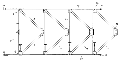
Figure 14 shows part of a bridge 62 using the
components of Figures 8 to 13. It shows web members 40,
upper chords 48 joined at 63, lower chords 53 joined at
64, end posts 58, transoms 65 extending between the web
members and between the end posts, and part of a deck 66
laid on the transoms.