Note: Descriptions are shown in the official language in which they were submitted.
CA 02408021 2002-10-15
439BA
FLEI~LIBI l~ FRAMINiC STATION TOOL GATE
CHANGfIYG METHOD AND t~PPARATUS
s
Reference to Related Application
Applicant claims the benefit of provisional application, Serial No.
60/329,767, filed
October 16, 2001.
to BACKGROijND OF THE INVENTION
Field of the Invention
This invention relates generally to a flexible framing station tool changing
method and
apparatus and more specifically to a method and apparatus for changing out
framing station side
and underbody tooling gates.
Description of the Relat~A~,rt Including In~ormatlo~,D~,,sclosed Under 37 CFR
1_97 and 1.98
In manufacturing automotive bodies, various body components such as roof,
floor and side
body sections must be joined together. In many framing systems, the body
components are first
loasely "toy-tabbed" together before they are welded. Toy tabbing allows
enough freedom of
relative movement between the body components to properly locate them before
welding. The toy-
tabbed body assembly is then moved to a framing station where locating
fixtures e~igage it. The
locating fixtures are carried by a pair of framing gates that are moved toward
either side of the
body by a framing drive system. The gates positively locate and hold the
loosely assembled body
components together long enough for welding machines or human welders to form
enough welds
between the body components to hold them rigidly together. Such systems
typically include both
CA 02408021 2002-10-15
side gates that engage vehicle bodies from the sides and underbody tooling
support beams that
engage vehicle bodies from below.
Some flexible framing systems include several interchangeable fi~aming gate
pairs, each of
which is configured to support a specific automotive body configuration.
Flexible framing systems
of this type can be reconfigured to accommodate a difrerent body style simply
by removing one
gate pair from a framing station and installing another.
A flexible framing system of this type may include both side tool gates and
underbody tool
support beams interchangeably supported adjacent a vehicle body assembly line
conveyor. The
conveyor in such a system passes through the framing station and supplies a
series of loosely
assembled vehicle bodies to the fiamimg station for welding. The station
supports side tool gates on
either side of the path that the vehicle bodies follow into the framing
station on the conveyor. The
station in such a system also supports underbody tool support beams beneath
the path of such
vehicle bodies. Each set of side gates and underbody beams (gate-beam set) is
dedicated to a
specific velicle body configuration, so the gate-beam sets are interchanged in
preparation for
changes in the type or configuration of vehicle body to be produced on the
assembly line. Each
firming gate and underbody beam carries tools in the form of locating fixtures
and clamps that are
positioned to positively locate and hold sub-elements of a specific vehicle
body configuration in
proper positions relative to each other for welding when the gates are
supported in respective
framing positions.
For example, United States Patent No. 6,293,454 issued 25 September 2001 to
Zhang et al.,
discloses a flexible framing station having underbody framing gates. The
underbody framing gates
are removably supportable at the framing station. A framing gate drive
removably supports one of
the underbody framing gates at a time at the framing station and moves it
between stowed and
2
CA 02408021 2002-10-15
framing positions. In the stowed position an underbody framing gate is spaced
downward from the
conveyor. In the framing position, an underbody framing gate engages the
underside of a vehicle
body carried by the conveyor in the framing station.
United States Patent No. 5,560,535 issued 1 October, 1996 to Miller et al.
discloses framing
gate pairs and an underbody support removably supportable at a framing
station. A pair of upright
side gate supports are movably supported at the framing station and detachably
support one of the
framing gate pairs at a time for reciprocal motion between respective stowed
and franning positions.
In the stowed position, the side gates are spaced from and generally parallel
to either side of a
vehicle body assembly line path passing between them In the framing positions
the side gates are
t o disposed closer to the vehicle body assembly line path such that when a
vehicle body assembly is
disposed between the side gates of a side gate pair on the assembly line path,
the locating fixtures
supported on the gates engage and hold sub-elements of that vehicle body
assembly in proper
positions relative to each other for welding. A harmonic framing gate drive is
operably connected
to the side gate supports and moves the supports through a reciprocal motion
that carries the gates
1 s between their stowed and framing positions. However, neither the Shang et
al. system nor the
Miller et al. system can install, remove, and store the underbody support
together with the framing
gate pairs
Brief Summa_rv of the Inveg~ion
2o According to the invention, an apparatus is provided for changing out
framing station side
and underbody tooling. The apparatus includes a framing station configured to
be disposed along a
vehicle body assembly line in a position to receive and hold vehicle bodies
for welding. A framing
gate pair is interchangeably supportable at the framing station and includes
two side gates. Each
CA 02408021 2002-10-15
side gate carries tools positioned and configured to positively locate and
hold sub-elements of a
vehicle body in predetermined positions relative to one another when the two
side gates are
supported in respective framing positions on either side of a vehicle body
received at the framing
station. An underbody tooling support beam pair is also interchangeably
supportable at the framing
s station and includes two underbody tooling support beams. Each gate of the
underbody tooling
support beam pair carries tools positioned and configured to positively locate
and hold sub-
elements of a vehicle body in predetermined positions relative to one another
when the two
underbody tooling support beams are supported in respective framing positions
beneath a vehicle
body received at the framing station. A transport positioner is disposed at
the framing station and
~ o is configured to move the framing gate pair and the tmderbody tooling
support beam pair from
respective supported positions at the fiamiag station. The t<~ansport
positioner is also configured to
interconnect the gates of the gate pair and the beams of the underbody tool
support beam pair into a
single gate-beam set and move the gate-beam set to a transport position for
removal from the
framing station.
~ s The invention also includes a method for changing out framing station side
and underbody
tooling. According to this method one can change out framing station side and
underbody tooling
by first providing a framing station along a vehicle body assembly line in a
position to receive and
hald vehicle bodies for welding. A framing gate pair and an underbody tooling
support beam pair
are supported fox framing operations at the framing station with each gate
including tools
2o configured and positioned to positively locate and hold sub-elements of a
vehicle body in
predetermined positions relative to one another. The gates and beams are moved
from their
respective supported positions at the framing station and interconnected into
a single gate-beam set.
The gate-beam set is then moved to a transport position and removed from the
framing station.
4
CA 02408021 2002-10-15
According to another aspect of the inventive method, a second gate-beam set is
provided
including an interconnected framing gate pair and underbody tooling support
beams connected to
the side gates. The second gate-beam set is moved onto the framing station,
and the individual
gates of the second set of gates are moved into respective supported positions
at the framing station
for framing operations.
Obj ects, features and advantages of this invention include providing a
flexible framing
station gate change out system that simplifies and speeds the process of
changing out and storing
side and underbody framing gates, and that allows side and underbody framing
gates to be
removed, transported, stored, and installed together as a single gate-beam
set.
Brief Descrlution of the Several Views~f a Drawl
These and other objects, features and advantages of this invention will be
apparent from the
following detailed description of the preferred embodiments) and best raode,
appended claims, and
accompanying drawings in which:
~ 5 FIG. 1 is a partially cut-away end view of one of two sides of an
apparatus constructed
according to the invention and showing a side and an underbody tooling support
beam of the
apparatus in respective framing positions relative to a vehicle body shown in
phantom;
FIG. 2 is a partially cut-away end view of the same side of the apparatus
shown in FIG. 1
and showing the underbody tooling support beam engaging the side gate with the
side gate still
2o supported on a movable gate support of the invention;
FIG. 3 is a partially cut-away end view of both sides of the apparatus of FIG.
1 and showing
the side and underbody tooling support beams interconnected as a single gate-
beam set in a
transport position;
s
CA 02408021 2002-10-15
FIG. 4 is a partially cut-away top view of one of the two sides of the
apparatus of FIG. 1
and a fragmentary top view of the other of the two sides of the apparatus of
FIG. 1; and
FIG. 5 is a side view of one of the two sides of the apparatus of FIG. 1 taken
along line 5-5
of )1'IG. 3.
Detailed Description of the Preferred Embodiment
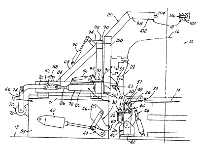
An apparatus for changing side and underbody framing gates is shown in the
drawings. The
apparatus 10 includes a framing station 12 disposed on a support surface 13
along a vehicle body
assembly line 14 in a position to receive and hold vehicle bodies 16 for
welding. The apparatus 10
also includes a framing gate pair 18 interchangeably supportable at the
framing station 12 and
including two framing gates 20. Each framing gate 20 carries tools 22 such as
locating fixtures and
clamps. The locating fixtures are for moving the sub-elements of a vehicle
body 16 into desired
positions relative to one another for welding, and the clamps are to hold the
sub-elements in those
relative positions during welding operations. The tools 22 positively locate
and hold sub-elements
of a vehicle body 16 in pre-determined positions relative to one another when
the two flaming
gates 20 are supported in respective framing positions on either side of a
vehicle body 16 received
at the framing station 12 as shown in FIGS. 1 and 5. The apparatus 10 also
includes an underbody
tooling support beam pair 24 interchangeably supportable at the framing
station 12 and including
tv~~o underbody tooling support beams 26. Each underbody tooling support beam
26 also carries
tools 22 such as locating fixtures and clamps. The underbody tools 23 are
positioned to positively
locate and hold sub-elements of a vehicle body 16 in predetermined positions
relative to one
another when the two underbody tooling support beams 26 are supported in
respective framing
positions beneath a vehicle body 16 received at the flaming station 12 as best
shown in FIG. 1. A
6
CA 02408021 2002-10-15
transport positioner 30 is disposed at the framing station 12 and moves the
framing gate pair 18 and
the underbody tooling support beam pair 24 from restive supported positions at
the flaming
station 12 to a transport position, as best shown in FIG. 3, for removal from
the framing station 12.
The transport positioner 30 is also designed to move a gate-beam set 32 from
the transport
position in the framing station to respective supported positions on the
Beaming station 12 for
framing operations. In other words, the transport positioner 30 assembles
gates 20 and beams 26
into a gate-beam set 32 for transport and separates gate-beam sets 32 at the
framing station 12 and
positions the individual gates 20 and beams 26 of such gate-beam sets 32 for
flaming operations.
Each framing gate 20 of a framing gate pair 18 is connected to and supported
on one of the
to underbody tooling support beams 26 of a corresponding uaderbody tooling
support beam pair 24
when the two gate pairs 18, 24 are interconnected into a single gate-beam set
32 for transport. A
gate interconnect 34 of the transport positioner 30 connects the underbody
tooling support beams
26 and framing gates 20 as described above aad includes gate interconnect
brackets 36 fixed along
a bottom edge of each of the under body beams 26. Gate wheels 38 are attached
to each of the gate
interconnect brackets 36 in positions to support the underbody tooling support
beams 26 for
transport when the gates 20 and beams 26 are interconnected as a gate-beam set
32.
The gate interconnect 34 also includes four beam lifters 40, two of which are
supported on
the support surface 13 beneath one of the underbody tooling support beams 26.
Each of the four
beam lifters 40 includes a lifter housing 42 and an extendable lifter rod 44
supported within the
lifter housing 42. Four lifter pins 46 are mounted on upper ends of the
respective lifter rods 44.
The lifter pins 46 are normally snugly received in corresponding lifter pin
apertures 48 formed
along the bottom edges of the underbody tooling support beams 26.
7
CA 02408021 2002-10-15
The gate interconnect 34 of the transport positioner 30 further includes four
side gate
interconnect bracket pins 50 mounted on and extending upward fiom respective
top surfaces of the
respective gate interconnect brackets 36. The side gate interconnect pins 50
are positioned to be
snugly received in corresponding interconnect bracket pin apertures 52 formed
along bottom
surfaces of the framing gates 20.
As shown in FIGS. 1-3, the gate interconnect 34 further includes four gate
lift pins 53 that
extend downwardly from respective gate lift brackets 55. The gate lift
brackets 55 extend
horizontally inward from the framing gates 20 and position the gate lift pins
53 in vertical
alignment with corresponding gate lift pin apertures 57 formed in upper
surfaces of the underbody
1 o tooling support beams 26 when the framing gates 20 are in respective pre-
transport positions as
shown in FIG. 2.
As best shown in FIG. 1, support beam clamps 54 engage each of the underbody
tooling
support beams 26 such that the underbody tooling support beams 26 do not sway
or rock on the
lifter housing 42 while the framing station 12 is in use and the beam lifters
40 are in respective
down positions holding the underbody tooling support beams 26 in respective
framing positions.
The underbody tooling support beam lifters move the underbody tooling support
beams 26 between
their framing positions as shown in FIG. 1, and the positions shown in FIG. 2.
The underbody
tooling support beams 26 connect to their respective corresponding flaming
gates 20 with the side
gate interconnect pins 50 engaging the interconnect bracket pin apertures 52
when the underbody
2o tooling support beams 26 are in their respective gate attachment positions
as shown in FIG. 2.
The transport positioner 30 also includes four lift arms 56, two of which are
pivotally
mounted on one of two framing gate support bases 58 disposed on each side of
the vehicle body
assembly line 14. Each pair of lift arms S6 carries one of two parallel
framing station rails GO
8
CA 02408021 2002-10-15
between respective retracted positions, as shows in FIGS. 1 and 2, and lower
support positions, as
shown in phantom in FIG. 2. In their lower support positions, the framing
station rails 60 engage
the gate wheels 38 of respective underbody tooling support beams 26 so that,
together, the two rails
60 are supporting the weight of an intercormected gate-beam set 32. In their
retracted positions, the
fraaning station rails 60 are held clear of the underbody tooling support
beams 26 so that when the
underbody tooling support beams 26 move between the framing and transport
positions there is no
contact between the underbody tooling support beams 26 and the rails 60.
The lift arms 56 further carry the framing station rails 60 upward from their
lower support
positions to respective upper support positions that position the gate-beam
set 32 in a transport
t o position as shown in FIG. 3. When a supports gate-beam set 32 is in its
transport position the
framing station rails 60 are aligned with other rails (not shown) positioned
outside the framing
station to move gate-beam sets 32 on and off the fi~aming station 12. Each of
the gate lift arms 56
is driven by a lift arm actuator 62 drivingly coupled to a linkage 64 that is,
in turn, drivingly
coupled to a gate lift arm. Through the linkages 64, the lift arm actuators 62
drive the respective
gate lift arms 56 and framing station rails 60 between their retracted
positions and their upper and
lower support positions.
The framing gates 20 are movable past their respective framing positions,
shown in FIG. 1,
to their respective pre-transport positions, shown in FIG. 2. In their pre-
transport positions, the
framing gates 20 engage one another, the side gate interconnect pins 50 on the
gate interconnect
brackets are vertically aligned below the interconnect bracket pin apertures
52 in the framing gates
20, and, as described above, the gate lift pins 53 are vertically aligned
above their corresponding
gate lift pin apertures 57 in the underbody tooling support beams 26.
9
CA 02408021 2002-10-15
To move the framing gates 20 between their framing and pre-transport
positions, as well as
respective stowed positions shown in FIG. 3, the framing station 12 includes a
framing gate drive
66. The framing gate drive 66 is operably connected to the framing gates 20
through four framing
gate supports 68. In the stowed positions the flaming gates 20 are disposed in
positions spaced
s from and generally parallel to a vehicle body assembly line 14 path passing
between them. In the
framing position shown in Figure 1, the framing gates 20 are disposed closer
to the vehicle body
assembly line 14 path such that when a vehicle body 16 assembly is disposed
between the gates 20
on the path, the tools 22 supported on the gates 20 engage and hold sub-
elements of that vehicle
body 16 assembly in proper positions relative to each other for subsequent
welding operations at
t o the framing station I 2.
The framing gate drive 66 includes harmonic drives 70 that move the framing
gate supports
68 through a lateral reciprocal motion that carry the framing gates 20 between
their respective
stawed and framing positions on either side of a vehicle body 16 during
framing operations. Each
of the framing gate supports 68 is mounted on a pair of parallel low friction
frame support rails 71.
i5 Each pair of frame support rails 71 is fixed to a top surface of one of the
two frame support bases
58. Each harmonic drive 70 includes a reversible motor 72 that drives an arm
74 and a link 76 that
is coupled to one of the framing gate supports 68. The rotation of the motors
72 back and forth
causes the arms 74 and the links 76 to reciprocate back and forth driving the
supports 68 and the
framing gates 20 between their stowed and framing positions. In other
embodiments, the gate drive
2o mechanism may be of any type known in the art to include the mechanism
disclosed in U.S. Patent
No. 5,560,535 issued October 1, 1996 and assigned to the assignee of the
present invention.
As best shown in FIGS. 1-3, the fi~arning gate drive 66 also includes a side
gate transport
drive 78 of the transport positioner 30. The side gate transport drive 78
includes a gate position
io
CA 02408021 2002-10-15
cylinder 80 that moves the framing gate supports 68 in such a way as to the
drive the framing gates
20 past their respective framing positions shown in FIG. 1 to their respective
pre-transport
positions shown in FIG. 2. To accomplish this, each link 76 is attached to a
slide 82 that is coupled
to clevis 84 mounted on the end of a drive rod 86 of a corresponding gate
position cylinder 80.
s Lock pins 88 engage apertures 89 in the frame gate support 68 to fix the
positions of the slides 82
relative to their corresponding supports 68. Distal ends of the gate cylinders
80 are attached to
their corresponding supports 68. With the lock pins 88 in place as shown in
FIG. 1, the gate
position cylinders 80 are not able to extend the drive rods and the positions
of the gates are
controlled by the links 76 and the harmonic drives 70 for framing operations.
With the lock pin 88
1o removed as shown in FIGS. 2 and 3, the positions of the side gates 20 are
controlled by the gate
position cylinders 80. Once the harmonic drives 70 have positioned the gates
in their respective
framing positions, the lock pins 88 can be removed and the gate position
cylinders 80 used to move
the firaming gates 20 from their respective Beaming positions to their
respective pre-transport
positions.
~ 5 Each of the framing gates 20 is removably mounted on its frame support 68
by upper and
lower gate mounting brackets 90 that mate with upper and lower gate mounting
pins 92 supported
on the gate supports 68. Gate mounting bracket clamps 94 are also supported on
the supports 68
and lock the upper and lower gate mounting brackets 90 on the gate mounting
pins 92 for framing
operations. The gate mounting bracket clamps 94 are actuated between engaged
and released
2o positions by gate clamp cylinders 96. With the gate mounting bracket clamps
94 open, the upward
motion of the framing station rails 60 from their lower to the upper support
positions disengages
the underbody tooling support beams 26 from their underbody tooling support
beam lifters and
disengages the framing gates 20 from the framing gate supports 68 as best
shown in FIG. 2.
I1
CA 02408021 2002-10-15
To interconnect the framing gates 20 in the pre-h~ansport and transport
positions, each
framing gate pair 18 includes a pair of releasably interconnecting extension
frames 98. Each
extension frame 98 is fixed along an upper edge of a lower tool-holding
portion 100 of each
framing gate 20 of each framing gate pair 18. The two extension frames 98 of
each framing gate
pain 18 releasably interconnect along respective interfacing edges of top
beams 102, 103 of the
extension frames 98. The top beams 102, 103 interconnect such that the framing
gates 20 are held
in relative positions accessible for engagement by the upright supports 68 of
the framing station I2
when a gate-beam set 32 is moved into the framing station 12. Interconnection
of the extension
frames 98 also spaces the gates 20 and interconnect brackets 36 properly for
the gate support
1 o wheels 38 to engage and be positioned to roll along the framing station
rails 60 during transport.
The interfacing edge of one of the extension frame top beams 102, 103 of each
gate pair
includes top beam locating pins 104 engageable with corresponding top beam pia
receptacles 106
in the interfacing edge of the other extension frame top beam I03. Engagement
of the top beam
locating pins 104 and their corresponding pin receptacles 106 positively
locates the top beams 102,
1 s 103 and therefore the side gates 20 of each framing gate pair 18 in
relation to one another for
transport and for subsequent engagement with the supports 68 upon delivery to
the framing station
12. Each framing gate pair 18 also includes one or more beam clamps as is
schematically shown at
108 in Figure 2. The beam clamps 108 hold the interconnecting extension frames
98 of each side
gate pair 18 together in a proper relative orientation for transport and
storage.
2o As shown in FIG. 3, each framing gate pair 18 includes two pairs of tie
bars 110 that
releasably connect between the two gates 20 of each framing gate pair 18. When
connected, each
pair of tie bars 110 forms an X configuration across opposite ends of the
Beaming gate pair 18. The
tae bars 110 hold the side gates 20 together and provide structural rigidity
for h~ansport and storage
12
CA 02408021 2002-10-15
of a gate-beam set 32. Each framing gate 20 of each framing gate pair 18
includes two vertically
spaced locking posts 112 on respective vertical end members I14 of the framing
gates 20. The
locking posts 112 each releasably engage one end of one of the tie bars 110 so
that the bars can be
easily installed for transport and storage and then removed for framing
operations after a gate-beam
set 32 has been newly installed at the framing station 12. The tie bars 110
each engage diagonally
opposite locking posts 112 to form the X configuration.
In practice, a gate-beam set 32 including both the framing gate pair I8 and
the underbody
tooling support beam pair 18, 24, can be removed from the framing station I2
by first actuating the
harmonic drives 70 to move the framing gates 20 of the framing gate pair 18
from their respective
1 o stowed positions (not shown) to their respective framing positions as
shown in FIG. 1. The
framing drive lock pins 88 are then removed from the slides 82 so that the
gate position cylinders
80 can be extended, moving the framing gate supports 6$ and the framing gates
20 inward from
their respective framing positions toward their respective pre-transport
positions as shown in FIG.
2. The gate position cylinders 80 are extended until the top beams 102 of each
of the framing gates
1s 2U abut one another and the top beam locating pins 104 of one top beam I02
are received into the
top beam pin receptacles 106 of the other top beam 103. In this position, the
side gate lift pins 53
are vertically aligned above their corresponding side gate lift pin apertures
57 in the underbody
tooling support beams 26 and the side gate intezconnect bracket pins 50 are
vertically aligned
below their corresponding interconnect bracket pin apertures 52 in the side
gates 20. The support
2o beam clamps 54 are then pulled out of engagement with their respective
underbody tooling support
beams 26, as shown in FIG. 2, so that the underbody tooling support beams 26
are free to be raised
by the lifter rods 44 and the lifter pins 46 to respective positions where
they engage the lifter pin
apertures 48. With the underbody tooling support beams 26 and their respective
raised pre-
13
CA 02408021 2002-10-15
transport positions, the side gate interconnect bracket pins 50 engage the
bracket pin apertures 52
and the side gate lift pins 53 engage the side gate lift pin apertures 57.
This coupling of pins and
sockets prevents relative sliding and rocking between the underbody tooling
support beams 26 and
the framing gates 20 during transport.
When the underbody tooling support beams 26 are in their raised pre-transport
positions as
shown in FIG. 2, the gate lift arms 56 can be raised by their respective
actuators and linkages until
the two framing station rails 60 contact the support wheels 38. The gate
mounting bracket clamps
94 are then actuated to open and release the gate mounting brackets 90. An
operator then places
the; cross tie bars 110 on the tie bar attachment posts. The lifter arm
actuators are then energized to
1 o raise the respective gate lift arms 56 causing the framing station rails
60 to lift the gate-beam set 32
from the pre-transport position to the transport position as shown in FIG. 3.
Alternatively, once the gates have been brought together so that the beams
102, 103 are in
contact, the lift arms 56 can be used to raise the gates and the underbody
tooling from the framing
position to the transport position in a single motion by first raising the
gates with the lift cylinders
15 40. The cross braces 110 are then attached to the mounting posts 112. The
lift arms 56 can then be
raised from the lowered position to the fully raised position by engaging the
wheels 38 with the
rails 60 and lifting the gates 20 off the gate mounting pins 92.
In moving the gate-beam set 32 from the pre-transport position to the
transport position
shown in FIG. 3, the gate mounting brackets 90 are lifted free of the gate
mounting pins 92 and the
2o underbody tooling support beams 26 are lifted off the lifter pins 46. The
gate position cylinder 80
then retracts the gate supports 68 away from the side gates 20 until the
vertical beams 102 of the
supports 68 are clear of the gate mounting brackets 90. A tractor mechanism or
other means is then
used to move the gate-beam set 32 including both side and underbady tooling
support beams 26 as
14
CA 02408021 2002-10-15
a unit out of the framing station 12. The support wheels 38 roll along the
fi~aming station rails 60
and onto other rail sections that form a rail path.
Once a gate-beam set 32 has been removed out of the framing station 12, a new
gate-beam
set 32 can be moved into the iiamnng station 12. The side gates 20 and
underbody support beams
26 of the new gate-beam set 32 are then moved into supports positions of the
framing station 12
by repeating in reverse order the sequence of events described above.
This description is intend~i to illustrate certain embodiments of the
invention rather than to
limit the invention. Therefore, it uses descriptive rather than limiting
words. Obviously, it's
possible to modify this invention from what the description teaches. Within
the scope of the
1 o claims, one may practice the invention other than as described.