Language selection

Search

Patent 2408024 Summary

Third-party information liability

Some of the information on this Web page has been provided by external sources. The Government of Canada is not responsible for the accuracy, reliability or currency of the information supplied by external sources. Users wishing to rely upon this information should consult directly with the source of the information. Content provided by external sources is not subject to official languages, privacy and accessibility requirements.

Claims and Abstract availability

Any discrepancies in the text and image of the Claims and Abstract are due to differing posting times. Text of the Claims and Abstract are posted:

  • At the time the application is open to public inspection;
  • At the time of issue of the patent (grant).
(12) Patent: (11) CA 2408024
(54) English Title: BRAKING DEVICE FOR A LIFT
(54) French Title: DISPOSITIF DE FREINAGE POUR UN ASCENSEUR
Status: Expired
Bibliographic Data
(51) International Patent Classification (IPC):
  • B66B 5/22 (2006.01)
(72) Inventors :
  • SIMMONDS, OLIVER (Switzerland)
  • HUGEL, STEFAN (Switzerland)
  • MAURY, JULIEN (Switzerland)
  • MORI, PETER (Switzerland)
  • AESCHLIMANN, PETER (Switzerland)
(73) Owners :
  • INVENTIO AG (Switzerland)
(71) Applicants :
  • INVENTIO AG (Switzerland)
(74) Agent: RICHES, MCKENZIE & HERBERT LLP
(74) Associate agent:
(45) Issued: 2010-01-19
(86) PCT Filing Date: 2001-05-23
(87) Open to Public Inspection: 2001-11-29
Examination requested: 2006-01-10
Availability of licence: N/A
(25) Language of filing: English

Patent Cooperation Treaty (PCT): Yes
(86) PCT Filing Number: PCT/CH2001/000316
(87) International Publication Number: WO2001/089973
(85) National Entry: 2002-11-04

(30) Application Priority Data:
Application No. Country/Territory Date
00810452.3 European Patent Office (EPO) 2000-05-25

Abstracts

English Abstract


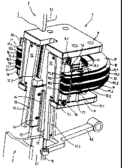
The invention relates to a brake device (6), acting upon a guide rail (2) and
comprising a housing (9) arranged on the yoke (4, 5), which serves as support
for spring assemblies (10) and/or for adjustment assemblies (11). The housing
(9) also serves as support and guide for V-guide elements (12), which in turn
fix and guide brake wedges (13) with brake linings (14). Connecting rods (15)
are connected at one end to the brake wedges (13) and are connected at the
other to an operating fork (8.2). During braking, the operating fork (8.2) is
displaced at the connecting rod end in the direction of the braking device
(6). The guided brake wedges (13) with brake linings (14) slide in the brake
device (6). At the same time the brake linings (14) are moved onto the guide
web (2.1) of the guide rail (2). The brake wedges (13) are moved in the brake
device (6) and the spring- and adjuster-assemblies (10, 11) are put under
load, which generates a braking force for stopping of a lift cabin or a
counterweight.


French Abstract

L'invention concerne un dispositif de freinage (6) agissant sur un rail de guidage (2) et comprenant un bâti (9) monté sur le châssis (4, 5) et servant de support pour des blocs-ressorts (10) et/ou des pièces d'ajustage (11). Ce bâti (9) sert également de support et de guide pour des éléments de guidage de coins (12), qui maintiennent et guident des coins d'écartement de frein (13) pourvus de garnitures de frein (14). Des bielles (15) sont reliées d'un côté aux coins d'écartement de frein (13) et de l'autre à une fourchette d'actionnement (8.2). Pendant le freinage, cette fourchette d'actionnement (8.2) est déplacée, côté bielles, en direction du dispositif de freinage (6). Les coins d'écartement guidés (13) glissent avec les garnitures de frein (14) dans le dispositif de freinage (6). Les garnitures de frein (14) sont déplacées simultanément sur l'âme (2.1) du rail de guidage (2). Les coins d'écartement de frein (13) sont déplacés dans le dispositif de freinage (6) et les blocs-ressorts et pièces d'ajustage (10, 11) sont contraints. Une force de freinage est alors produite pour arrêter une cabine d'ascenseur ou un contrepoids.

Claims

Note: Claims are shown in the official language in which they were submitted.


What is claimed is:

1. A braking device for an elevator with an elevator car and an counterweight
movable along guide rails in an elevator shaft, wherein the braking device is
arranged at
the elevator car or at the counterweight and in the case of excess speed stops
the
elevator car or the counterweight at the guide rails by means of spring
elements and
brake chocks, comprising: a plurality of spring elements of modular
construction, said
spring elements being selectively assembled for generating different braking
forces,
wherein said spring elements each are one of a spring packet and an adjusting
packet
and said spring packet and said adjusting packet are detachably connected at
ends
thereof with chock guide elements guiding the brake chocks.

2. The braking device according to claim 1 wherein said spring packet and said

adjusting packet are C-shaped.

3. The braking device according to claim 1 wherein said spring packet is
arranged
at a support body that acts on said chock guide elements.

4. The braking device according to claim 3 wherein said support body has an
associated groove formed therein for reception of each said spring packet.

5. A braking device for an elevator with an elevator car and a counterweight
that
are movable along guide rails in an elevator shaft, wherein the braking device
is
arranged at the elevator car or at the counterweight and in the case of excess
speed
stops the elevator car or the counterweight at the guide rails with spring
elements and
brake chokes, wherein the spring elements are of modular construction and
generate
different braking forces, comprising: a plurality of spring elements
constructed from
lamellae, each of said spring elements being one of a spring packet and an
adjusting
packet, each said spring packet being arranged at a support body that acts on
chock
guide elements guiding the brake chocks.

6. The braking device according to claim 5 wherein said spring elements are C-
shaped.

7. The braking device according to claim 5 wherein said spring elements are


6
detachably connected at ends with chock guide elements guiding the brake
chocks.
8. The braking device according to claim 5 wherein said support body has an
associated groove formed therein for receiving each of said spring packets.

9. A braking device for attachment to one of an elevator car and a
counterweight
that are movable along guide rails in an elevator shaft, wherein the braking
device is
actuated to engage a guide rail in the case of excess speed, comprising:
a housing;
a pair of brake chocks mounted on said housing and movable from a disengaged
position to a guide rail engaging position; and
at least one spring packet mounted on said housing and having opposed ends
connected to associated ones of said brake chocks, said at least one spring
packet
being of modular construction having lamellae selected to produce a
predetermined
braking force, and including at least one adjusting packet mounted on said
housing and
having opposed ends connected to an associated one of said brake chocks.

10. The braking device according to claim 9 wherein each end of said spring
packet
is detachably connected to said associated brake chock by a spring bracket.

Description

Note: Descriptions are shown in the official language in which they were submitted.


CA 02408024 2002-11-04

WO 01/89973 1 PCT/CH01/00316
DESCRIPTION

Braking device for a lift

The invention relates to a braking device for a lift with a lift cage and a
counterweight,
which are movable along guide rails in a lift shaft, wherein the braking
device is arranged
at the lift cage or at the counterweight and in the case of excess speed stops
the lift cage
or the counterweight at the guide rails by means of spring elements and brake
chocks.
There has become known from the patent specification US 5 782 319 a braking
device for
a lift, which stops the lift cage in the case of emergency. The lift cage
drives, by means of
an endless cable, a rotating speed limiter, which blocks in the case of a
specific excess
speed of the lift cage. The blocked speed limiter also blocks the endless
cable, but the lift
cage moves further downwardly, wherein the blocked endless cable, which is
connected
with a release lever mechanism of the braking device, trips the braking
device. In that
case two guided chocks of the braking device are pushed upwardly. The braking
force is
generated by friction between the chocks and the guide rail of the lift cage.
The braking
force is on the one hand dependent on the friction of the chocks on the guide
rail and on
the other hand dependent on a C-shaped compact spring packet, at the ends of
which
guides for the chocks are provided.

A disadvantage of the known device consists in that the spring packet and the
guides are
cast from one piece. The spring packet unit has to be manufactured in
accordance with
the respective braking force to be exerted, which increases the cost of the
braking device.
Here the invention will create a remedy. The invention as characterised in
claim 1 meets
the object of avoiding the disadvantages of the known device and of creating a
brake
device with a universal construction for stopping a lift cage or a
counterweight.

The advantages achieved by the invention are essentially to be seen in that a
simple
construction of the braking device is possible. The braking device consists of
only a few
different components. Further, it is advantageous that the braking device is
adaptible, with
the same components, to different braking forces. The braking device is thus
usable
without great outlay for lift cages or counterweights with different masses to
be braked.
Moreover, the braking device according to the invention offers the possibility
of fine


CA 02408024 2008-03-28

2
adjustment with respect to the braking force. The spring elements consist of
Iamellae
producible in simple manner. A greater or lesser number of lamellae can be
used in
accordance with the respective braking force.

In one aspect, the present invention resides in a braking device for an
elevator with an
elevator car and an counterweight movable along guide rails in an elevator
shaft,
wherein the braking device is arranged at the elevator car or at the
counterweight and
in the case of excess speed stops the elevator car or the counterweight at the
guide
rails by means of spring elements and brake chocks, comprising: a plurality of
spring
elements of modular construction, said spring elements being selectively
assembled
for generating different braking forces, wherein said spring elements each are
one of
a spring packet and an adjusting packet and said spring packet and said
adjusting
packet are detachably connected at ends thereof with chock guide elements
guiding
the brake chocks.

In a further aspect, the present invention resides in a braking device for an
elevator
with an elevator car and a counterweight that are movable along guide rails in
an
elevator shaft, wherein the braking device is arranged at the elevator car or
at the
counterweight and in the case of excess speed stops the elevator car or the
counterweight at the guide rails with spring elements and brake chokes,
wherein the
spring elements are of modular construction and generate different braking
forces,
comprising: a plurality of spring elements constructed from Iamellae, each of
said
spring elements being one of a spring packet and an adjusting packet, each
said
spring packet being arranged at a support body that acts on chock guide
elements
guiding the brake chocks.

In yet another aspect, the present invention resides in a braking device for
attachment
to one of an elevator car and a counterweight that are movable along guide
rails in an
elevator shaft, wherein the braking device is actuated to engage a guide rail
in the
case of excess speed, comprising: a housing; a pair of brake chocks mounted on
said
housing and movable from a disengaged position to a guide rail engaging
position;
and at least one spring packet mounted on said housing and having opposed ends
connected to associated ones of said brake chocks, said at least one spring
packet
being of modular construction having lamellae selected to produce a
predetermined
braking force, and including at least one adjusting packet mounted on said
housing
and having opposed ends connected to an associated one of said brake chocks.


CA 02408024 2008-03-28

2a
The present invention is explained in more detail by reference to the
accompanying
figures, in which:

Fig. 1 shows a lift cage with the braking device according to the invention,
Fig. 2 shows details of the braking device acting on a guide rail,

Fig. 3 shows a support body with spring elements,

Fig. 4 shows a section along the line A-A of Fig. 3 and

Fig. 5 shows a perspective illustration of the support body with the spring
elements.

Fig. 1 shows a lift cage 1 movable in a lift shaft which is not illustrated,
wherein the lift
cage 1 is guided by means of guide rails 2 extending over the shaft height.
The lift cage 1
provided with a door 1.1 is carried by a support frame 3 with a lower yoke 4
and an upper
yoke 5. A support cable (not illustrated), one end of which is connected with,
for example,
the upper yoke 5 and the other end of which is connected with a counterweight
(not
illustrated), is guided over a drive pulley (not illustrated). A respective
braking device 6,
which stops the lift cage in the case of emergency, is arranged at the lower
yoke 4 per
guide rail 2. The lift cage 1 drives, by means of an endless cable 7, a
rotating speed
limiter (not illustrated) which blocks in downward direction in the event of a
specific excess
speed of the lift cage 1. The blocked speed limiter also blocks the endless
cable 7 guided
over a tensioning roller (not illustrated) arranged in the shaft pit, but the
lift cage 1 moves
further downwardly, whereby the blocked endless cable 7 connected with a
trigger lever
mechanism 8 trips the braking device 6. The trigger lever mechanism 8
connected with
the endless cable 7 consists of a rotational axle 8.1 at which an actuating
fork 8.2, which
trips the braking device 6, is arranged. The actuating fork 8.2 of the
opposite braking
device 6 is actuated by means of a connecting rod 8.3 arranged at the
rotational axle 8.1.
When the endless cable 7, also termed limiter cable, is blocked, the
rotational axle 8.1 is


CA 02408024 2002-11-04

WO 01/89973 3 PCT/CH01/00316
rotated in clockwise sense as seen from the cage door 1.1. In that case the
actuating fork
8.2 is raised at the free end.

If the braking device is analogously arranged at the upper yoke 5, the lift
cage 1 can be
stopped in upward direction for cases of emergency. The braking device can
also be
arranged at the counterweight.

Fig. 2 shows details of the braking device 6 acting on a guide limb 2.1 of the
guiderail 2. In
order to make the details of the braking device 6 visible the guide rail 2 is
illustrated broken
away in the region of the braking device 6. The braking device 6 consists of a
housing 9
which is arranged at the yoke 4, 5 and which serves as a support for spring
packets 10
and/or for adjusting packets 11. The housing 9 also serves as a support and
guide for
chock guide elements 12, which in turn retain and guide brake chocks 13 with
brake
linings 14. A pushrod 15 engages at one end at the brake chock 13, and at the
other end
the pushrod 15 is pivotably connected with the actuating fork 8.2.

The spring packets 10 of modular construction and the adjusting packets 11 of
modular
construction are detachably connected at each end with a respective one of the
wedge
guide elements 12 by means of a respective spring bracket 16, wherein lugs
10.1 or 11.1
of the spring packets 10 or adjusting packets 11 prevent the packets 10, 11
from slipping
off the chock guide elements 12. The packets 10, 11 are interconnected at each
end by
means of, for example, a threaded pin 17 and nuts 17.1, wherein first seats
12.2 of the
chock guide elements 12 and at least one second seat 9.2 of the housing 9 hold
the
overall packet consisting of spring packets 10 and adjusting packets 11.

In the illustrated example a spring packet 10 consists of ten lamellae 10.2 of
the same
thickness and same material. The geometrically somewhat smaller adjusting
packets 11
consist, in the illustrated example, of three lametlae 11.2. The lamellae
10.2, 11.2 are, for
example, punched out of sheet metal. Other lamella materials or different
lamella
thicknesses are also possible. The lamellae 10.2, 11.2 can also have a shape
departing
from the illustrated C shape. The individual spring packets or adjusting
packets of the
braking device 6 can also have a different number of lamellae. Different
spring constants,
which have a direct effect on the braking force, can be produced in accordance
with the
respective number of lamellae, material, lamella thickness or lamella shape.


CA 02408024 2002-11-04

WO 01/89973 4 PCT/CH01/00316

The chock guide element 12 is guided in first grooves 9.1 of the housing 9 and
has an
extension 12.1. In the case of normal operation the brake chock 13 is held in
rest position
by means of the extension 12.1 and the pushrod 15.

In the case of emergency the limiter cable 7 is blocked by the speed limiter
detecting
excess speed. The actuating fork 8.2 is thereby, as illustrated further above,
moved at the
pushrod end in the direction of the braking device 6. The brake chocks 13,
which are
guided in second grooves 12.3 of the chock guide elements 12, with the brake
linings 14
slide in the braking device 6. At the same time the brake linings 14 are moved
against the
guide limb 2.1 of the guide rail 2. Due to the wedge-shaped arrangement of the
chock
guide elements 12 and the friction between the brake linings 14 on the guide
limb 2.1, the
brake chocks 13 are moved in the braking device 6 and the spring and adjusting
packets
10, 11 stressed, wherein the braking force, which is dependent on the friction
constant
between the brake linings 14 and the guide limb 2.1 as well as on the spring
constant, for
stopping the lift cage or the counterweight is generated.

As illustrated in Figs. 3 to 5, the spring packets can be arranged at a
support body 20,
wherein the support body 20, which is, for example, C-shaped, acts on the
chock guide
elements 12. The spring packets 21 consist of at least one lamella 21.1 and
are laid in
grooves 22 of the support body 20. In the illustrated example, three grooves
or three
spring packets 21 are provided. A greater or lesser number than three grooves
22 can
also be provided, wherein the grooves 22 can also be of different widths. The
spring
packets 21 laid in narrow grooves 22 can serve as adjusting packets. During
the braking
process the support body 20 and the spring packets 21 are stressed and the
braking force
for stopping the lift cage or the counterweight is produced. The braking
device 6 can be
provided with one or more support bodies 20.

Representative Drawing
A single figure which represents the drawing illustrating the invention.
Administrative Status

For a clearer understanding of the status of the application/patent presented on this page, the site Disclaimer , as well as the definitions for Patent , Administrative Status , Maintenance Fee  and Payment History  should be consulted.

Administrative Status

Title Date
Forecasted Issue Date 2010-01-19
(86) PCT Filing Date 2001-05-23
(87) PCT Publication Date 2001-11-29
(85) National Entry 2002-11-04
Examination Requested 2006-01-10
(45) Issued 2010-01-19
Expired 2021-05-25

Abandonment History

There is no abandonment history.

Payment History

Fee Type Anniversary Year Due Date Amount Paid Paid Date
Registration of a document - section 124 $100.00 2002-11-04
Application Fee $300.00 2002-11-04
Maintenance Fee - Application - New Act 2 2003-05-23 $100.00 2003-04-24
Maintenance Fee - Application - New Act 3 2004-05-24 $100.00 2004-04-22
Maintenance Fee - Application - New Act 4 2005-05-23 $100.00 2005-04-29
Request for Examination $800.00 2006-01-10
Maintenance Fee - Application - New Act 5 2006-05-23 $200.00 2006-04-26
Maintenance Fee - Application - New Act 6 2007-05-23 $200.00 2007-04-25
Maintenance Fee - Application - New Act 7 2008-05-23 $200.00 2008-04-30
Maintenance Fee - Application - New Act 8 2009-05-25 $200.00 2009-04-29
Final Fee $300.00 2009-10-27
Maintenance Fee - Patent - New Act 9 2010-05-24 $200.00 2010-05-07
Maintenance Fee - Patent - New Act 10 2011-05-23 $250.00 2011-05-12
Maintenance Fee - Patent - New Act 11 2012-05-23 $250.00 2012-05-11
Maintenance Fee - Patent - New Act 12 2013-05-23 $250.00 2013-05-13
Maintenance Fee - Patent - New Act 13 2014-05-23 $250.00 2014-05-13
Maintenance Fee - Patent - New Act 14 2015-05-25 $450.00 2015-06-01
Maintenance Fee - Patent - New Act 15 2016-05-24 $450.00 2016-05-09
Maintenance Fee - Patent - New Act 16 2017-05-23 $450.00 2017-05-15
Maintenance Fee - Patent - New Act 17 2018-05-23 $450.00 2018-05-14
Maintenance Fee - Patent - New Act 18 2019-05-23 $450.00 2019-05-14
Owners on Record

Note: Records showing the ownership history in alphabetical order.

Current Owners on Record
INVENTIO AG
Past Owners on Record
AESCHLIMANN, PETER
HUGEL, STEFAN
MAURY, JULIEN
MORI, PETER
SIMMONDS, OLIVER
Past Owners that do not appear in the "Owners on Record" listing will appear in other documentation within the application.
Documents

To view selected files, please enter reCAPTCHA code :


To view images, click a link in the Document Description column. To download the documents, select one or more checkboxes in the first column and then click the "Download Selected in PDF format (Zip Archive)" or the "Download Selected as Single PDF" button.

List of published and non-published patent-specific documents on the CPD .

If you have any difficulty accessing content, you can call the Client Service Centre at 1-866-997-1936 or send them an e-mail at CIPO Client Service Centre.


Document
Description 
Date
(yyyy-mm-dd) 
Number of pages   Size of Image (KB) 
Claims 2002-11-05 1 35
Abstract 2002-11-04 2 117
Claims 2002-11-04 1 35
Drawings 2002-11-04 3 102
Description 2002-11-04 4 210
Representative Drawing 2002-11-04 1 61
Cover Page 2003-02-07 2 68
Claims 2008-03-28 2 74
Description 2008-03-28 5 260
Representative Drawing 2009-12-21 1 21
Cover Page 2009-12-21 2 61
Prosecution-Amendment 2006-01-10 1 32
PCT 2002-11-04 8 300
Assignment 2002-11-04 3 127
Prosecution-Amendment 2002-11-04 3 113
PCT 2002-11-05 3 160
Correspondence 2003-02-05 1 23
Assignment 2003-02-27 4 147
Prosecution-Amendment 2008-03-28 9 311
Prosecution-Amendment 2007-10-01 2 53
Prosecution-Amendment 2008-07-31 2 41
Prosecution-Amendment 2008-12-17 5 178
Correspondence 2009-10-27 1 50