Language selection

Search

Patent 2408079 Summary

Third-party information liability

Some of the information on this Web page has been provided by external sources. The Government of Canada is not responsible for the accuracy, reliability or currency of the information supplied by external sources. Users wishing to rely upon this information should consult directly with the source of the information. Content provided by external sources is not subject to official languages, privacy and accessibility requirements.

Claims and Abstract availability

Any discrepancies in the text and image of the Claims and Abstract are due to differing posting times. Text of the Claims and Abstract are posted:

  • At the time the application is open to public inspection;
  • At the time of issue of the patent (grant).
(12) Patent Application: (11) CA 2408079
(54) English Title: LOCK NUT
(54) French Title: CONTRE-ECROU
Status: Deemed Abandoned and Beyond the Period of Reinstatement - Pending Response to Notice of Disregarded Communication
Bibliographic Data
(51) International Patent Classification (IPC):
  • F16B 39/282 (2006.01)
  • B60B 27/00 (2006.01)
  • F16B 33/00 (2006.01)
  • F16B 37/00 (2006.01)
(72) Inventors :
  • WINKER, ALEXANDER (Germany)
(73) Owners :
  • METALLWARENFABRIK HERMANN WINKER GMBH & CO., KG
(71) Applicants :
  • METALLWARENFABRIK HERMANN WINKER GMBH & CO., KG (Germany)
(74) Agent: MACRAE & CO.
(74) Associate agent:
(45) Issued:
(22) Filed Date: 2002-10-15
(41) Open to Public Inspection: 2003-04-30
Availability of licence: N/A
Dedicated to the Public: N/A
(25) Language of filing: English

Patent Cooperation Treaty (PCT): No

(30) Application Priority Data:
Application No. Country/Territory Date
201 17 635.1 (Germany) 2001-10-31

Abstracts

English Abstract


The invention relates to a lock nut (1) for bearing, especially a wheel
bearing of vehicles,
wherein the bearing has a universal shaft, introducing the torque via a
splining, and a flange,
which is axially secured to the universal shaft by a screw connection.
According to the invention
they Lock nut (1) consists of a solid nut body (10), having a flange (11),
from which extends
axially a neck projection (12), being provided with an annular shroud (t3) at
its end surface (14),
from which at least two claws (15) extend radially.
(Fig.1)


Claims

Note: Claims are shown in the official language in which they were submitted.

Claims
1. A lock nut (1) for a bearing, especially a wheel bearing of vehicles,
wherein
the bearing has a universal shaft, introducing the torque via a splining, and
a flange, which is axially secured to the universal shaft by a screw
connection, characterized in that the lock nut (1) consists of a solid nut
body
(10), having a flange (11), from which extends axially a neck projection (12),
being provided with an annular shroud (13) at its end surface (14), from
which at least two claws (15) extend radially.
2. A lock nut according to claim 1, further characterized in that the nut body
(10) is a hot or cold pressed part.
3. A lock nut according to claim 1, further characterized in that the flange
(11 )
has a much larger outer diameter in relation to the neck projection (12),
preferably in the ratio of 2:1.
4. A lock nut according to claims 1 to 3, further characterized in that the
nut
body (10) is provided with a central threaded borehole (16).

5. A lock nut according to claims 1 to 4, further characterized in that the
outer
diameter of the cylindrical neck projection (12) and the outer diameter of the
annular shroud (13) are of equal dimension.
6. A lock nut according to claims 1 to 5, further characterized in that the
claws
(15) are fashioned as lobes extending tangentially from the annular shroud
(13).
7. A lock nut according to claims 1 to 6, further characterized in that the
flange
(11) on its lateral surface is provided with a toothing (17) for engaging with
an installation tool.
8. A lock nut according to claim 7, further characterized in that the toothing
(17) is of hexagonal or preferably twelve-point configuration.

Description

Note: Descriptions are shown in the official language in which they were submitted.


CA 02408079 2002-10-15
LOCK NUT
Specification
The present invention concerns a lock nut (1) for a bearing, especially a
wheel
bearing of vehicles, wherein the bearing has a universal shaft which
introduces
the torque across a splining, and a flange, which is axially fastened to the
universal shaft by a screw connection.
A nut of this kind is known from DE 195 43 436 C2. This document discloses a
sleevelike threaded nut, which is used on a universal shaft of motor vehicle
wheels to secure a wheel flange in a wheel bearing. In this case, the
sleevelike
threaded nut is screwed onto a threaded journal fom~ed on the universal shaft
and its axially resilient clamping flange lies against the wheel flange with
prestress. The clamping flange passes into a hexagonal recess, which serves to
fasten the threaded nut onto the threaded journal of the shaft. Notches are
provided at the outer circumference of the threaded portion of the nut, which
engage in a splining to secure the threaded nut, transferring the torque from
the
universal shaft to the wheel flange. In any case, the prestressing force of
the
bearing is produced by forming the inner end of the hub shaft provided on the
wheel flange radially outward into a bead, which thrusts against the roller
bearing
races that are shoved onto the hub shaft, as is also described in patent DE
4,339,847 C1. This kind of nut serves only as a captive device with slight

CA 02408079 2002-10-15
clamping force, so that the described configuration as a sheet metal part is
sufficient.
Practice has shown that the familiar sleevelike threaded nut does not meet the
requirements for the clamping force, due to the constantly occurring load
changes at the wheel bearing, especially when braking and accelerating the
vehicle in curves. The clamping force of this threaded nut produced as a deep-
drawn sheet metal part can slacken considerably, which is not acceptable for
safety reasons. Furthermore, because of the flexible design of the clamping
flange of the sleevelike threaded nut, moisture cannot be reliably prevented
from
getting into the region of the splining. Thus, the splining may become
corroded,
so that a reliable transmission of the torque is no longer guaranteed.
The tooling expenses and the production costs are considerable for the
sleevelike threaded nut manufactured as a deep-drawn part.
The object of the present invention now consists in furnishing a lock nut
which
permanently withstands the high loads, such as the high requirements when
operating a vehicle, and which reliably prevents moisture from getting inside
the
bearing. Furthermore, the lock nut should be simple in design and economical
to
produce.

CA 02408079 2002-10-15
The solution consists in a lock nut with the features of patent claim 1. The
lock
nut according to the invention is characterized in that it consists of a solid
nut
body, having a flange, from which a neck projection extends axially, being
provided at its end surface with an annular shroud, from which at least two
claws
extend radiaiiy.
This configuration of the invention has the effect that, due to the high
strength of
the nut body, the lock nut can be tightened much more firmly, so that the
clamping force is considerably increased. This means that the axial tension
between the universal shaft and the flange is so great that the bearing
functions
reliably over the long term, even under heavy load, such as rough driving
conditions in the case of a wheel bearing, and no looseness occurs.
Furthermore, the structure is pressed together so firmly that moisture is
prevented from getting into the splining. Thanks to the simple construction of
the
lock nut of the invention, its production is cost-effective. The invented
design also
makes it possible to produce and maintain the required bearing prestressing
force for the axial clamping between universal shaft and flange, if the
bearing
design so requires. An economical fabrication is achieved in particular by the
fact
that the nut body is a hot or cold pressed part.
Specifically, the Lock nut according to the invention is configured such that
the
flange in relation to the neck projection has a much larger outer diameter,
which
is preferably in the ratio of 2:1. Furthermore, the flange is provided on its
lateral

CA 02408079 2002-10-15
4
surface with a toothing to engage with an installation tool. This toothing can
be
hexagonal or preferably twelve-point. In this way, a large torque can be
exerted
by an installation tool on the lock nut, resulting in a firm seating of the
same on
the universal shaft. At the same time, a reliable fastening of the universal
shaft
and the flange, as well as the roller bearing sitting on the hub connected to
the
flange, is achieved. The roller bearing is joined to a shock absorber by means
of
screws.
The lock nut is provided with a central threaded boreho~ for screwing onto a
threaded journal formed on the universal shaft.
To simplify the construction of the nut body and thus achieve an economical
fabrication of the same, the outer diameter of the cylindrical neck projection
and
the outer diameter of the annular shroud are the same size. The claws are
formed as lobes extending tangentially away from the annular shroud.
Thus, the present invention provides a lock nut which is simple and economical
to produce, which can be screwed together and tightened with optimal force,
and
which is reliably protected against loosening and getting lost. Furthermore,
the
lock nut according to the invention can also be used with open bearings, i.e.,
it is
also suitable to being mounted on a bearing. Preferably, the entire bearing
prestressing force, which depending on the dimensions, amounts to 60 to 100

CA 02408079 2002-10-15
Kilo-Newtons, can be withstood by the lock nut. Thus, the invented lock nut
can
be used in a broad fiekf of application.
An example of embodiment of the present invention is explained more closely
hereafter by means of the enclosed drawing. This shows:
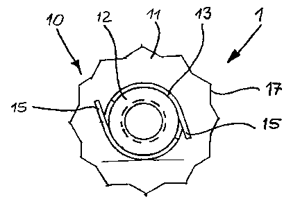
Figure 1 a schematic, not dimensionally true representation of the invented
lock nut in top view, and
Figure 2 a schematic, not dimensionally true representation of the lock nut of
figure 1, in cross section.
An example of embodiment of the invented lock nut is schematically depicted in
figures 1 and 2. The lock nut 1 consists of a nut body 10, which has a large
flange 11. From the flange 11 there extends a neck projection 12 in axial
direction. On the end surface 14 of the neck projection 12 is formed an
annular
shroud 13, which likewise extends in axial direction.
In the example of embodiment shoHm for the lock nut 1, the outer diameter of
the
neck projection 12 and the outer diameter of the annular shroud 13 are of the
same dimension. Two opposite claws 15 are punched out from the annular
shroud 13 and bent radially outward.

CA 02408079 2002-10-15
6
These claws 15 engage with the splining formed between the flange and the
universal shaft to secure the lock nut 1. In the example of embodiment, the
claws
15 are configured as lobes extending tangentially away from the annular shroud
13. Any other suitable configuration and arrangement for the claws '! 5 is
also
conceivable.
For screwing together and achieving optimal clamping force, the lateral
surface
of the flange i 1 is provided with a toothing 17, which can engage with an
installation tool. The toothing 17 can be hexagonal, or also finrelve-point,
as in the
example of embodiment.
With the invented lock nut 1, a reliable and secure fastening of a flange onto
a
universal shaft, such as a wheel flange, as described in patent DE 195 43 436
C2, is possible under cost-effective conditions. At the same tine, the
invented
lock nut 1 keeps moisture out from the inside of the bearing. Furthermore,
with
the invented lock nut the required bearing prestressing force can be produced
and maintained, if the bearing design requires such in the particular
application.

Representative Drawing
A single figure which represents the drawing illustrating the invention.
Administrative Status

2024-08-01:As part of the Next Generation Patents (NGP) transition, the Canadian Patents Database (CPD) now contains a more detailed Event History, which replicates the Event Log of our new back-office solution.

Please note that "Inactive:" events refers to events no longer in use in our new back-office solution.

For a clearer understanding of the status of the application/patent presented on this page, the site Disclaimer , as well as the definitions for Patent , Event History , Maintenance Fee  and Payment History  should be consulted.

Event History

Description Date
Application Not Reinstated by Deadline 2008-10-15
Time Limit for Reversal Expired 2008-10-15
Deemed Abandoned - Failure to Respond to Maintenance Fee Notice 2007-10-15
Inactive: Abandon-RFE+Late fee unpaid-Correspondence sent 2007-10-15
Inactive: IPC from MCD 2006-03-12
Application Published (Open to Public Inspection) 2003-04-30
Inactive: Cover page published 2003-04-29
Letter Sent 2003-02-11
Amendment Received - Voluntary Amendment 2003-01-20
Inactive: Single transfer 2002-12-17
Inactive: First IPC assigned 2002-12-17
Inactive: Courtesy letter - Evidence 2002-12-10
Inactive: Filing certificate - No RFE (English) 2002-12-03
Filing Requirements Determined Compliant 2002-12-03
Application Received - Regular National 2002-12-02

Abandonment History

Abandonment Date Reason Reinstatement Date
2007-10-15

Maintenance Fee

The last payment was received on 2006-10-13

Note : If the full payment has not been received on or before the date indicated, a further fee may be required which may be one of the following

  • the reinstatement fee;
  • the late payment fee; or
  • additional fee to reverse deemed expiry.

Please refer to the CIPO Patent Fees web page to see all current fee amounts.

Fee History

Fee Type Anniversary Year Due Date Paid Date
Application fee - standard 2002-10-15
Registration of a document 2002-12-17
MF (application, 2nd anniv.) - standard 02 2004-10-15 2004-10-14
MF (application, 3rd anniv.) - standard 03 2005-10-17 2005-08-24
MF (application, 4th anniv.) - standard 04 2006-10-16 2006-10-13
Owners on Record

Note: Records showing the ownership history in alphabetical order.

Current Owners on Record
METALLWARENFABRIK HERMANN WINKER GMBH & CO., KG
Past Owners on Record
ALEXANDER WINKER
Past Owners that do not appear in the "Owners on Record" listing will appear in other documentation within the application.
Documents

To view selected files, please enter reCAPTCHA code :


To view images, click a link in the Document Description column. To download the documents, select one or more checkboxes in the first column and then click the "Download Selected in PDF format (Zip Archive)" or the "Download Selected as Single PDF" button.

List of published and non-published patent-specific documents on the CPD .

If you have any difficulty accessing content, you can call the Client Service Centre at 1-866-997-1936 or send them an e-mail at CIPO Client Service Centre.


Document
Description 
Date
(yyyy-mm-dd) 
Number of pages   Size of Image (KB) 
Description 2002-10-15 6 204
Abstract 2002-10-15 1 12
Claims 2002-10-15 2 43
Drawings 2002-10-15 1 14
Representative drawing 2003-01-08 1 7
Cover Page 2003-04-04 1 32
Filing Certificate (English) 2002-12-03 1 159
Courtesy - Certificate of registration (related document(s)) 2003-02-11 1 107
Reminder of maintenance fee due 2004-06-16 1 109
Reminder - Request for Examination 2007-06-18 1 118
Courtesy - Abandonment Letter (Request for Examination) 2007-12-24 1 167
Courtesy - Abandonment Letter (Maintenance Fee) 2007-12-10 1 175
Correspondence 2002-12-03 1 24