Sélection de la langue

Search

Sommaire du brevet 2408079 

Énoncé de désistement de responsabilité concernant l'information provenant de tiers

Une partie des informations de ce site Web a été fournie par des sources externes. Le gouvernement du Canada n'assume aucune responsabilité concernant la précision, l'actualité ou la fiabilité des informations fournies par les sources externes. Les utilisateurs qui désirent employer cette information devraient consulter directement la source des informations. Le contenu fourni par les sources externes n'est pas assujetti aux exigences sur les langues officielles, la protection des renseignements personnels et l'accessibilité.

Disponibilité de l'Abrégé et des Revendications

L'apparition de différences dans le texte et l'image des Revendications et de l'Abrégé dépend du moment auquel le document est publié. Les textes des Revendications et de l'Abrégé sont affichés :

  • lorsque la demande peut être examinée par le public;
  • lorsque le brevet est émis (délivrance).
(12) Demande de brevet: (11) CA 2408079
(54) Titre français: CONTRE-ECROU
(54) Titre anglais: LOCK NUT
Statut: Réputée abandonnée et au-delà du délai pour le rétablissement - en attente de la réponse à l’avis de communication rejetée
Données bibliographiques
(51) Classification internationale des brevets (CIB):
  • F16B 39/282 (2006.01)
  • B60B 27/00 (2006.01)
  • F16B 33/00 (2006.01)
  • F16B 37/00 (2006.01)
(72) Inventeurs :
  • WINKER, ALEXANDER (Allemagne)
(73) Titulaires :
  • METALLWARENFABRIK HERMANN WINKER GMBH & CO., KG
(71) Demandeurs :
  • METALLWARENFABRIK HERMANN WINKER GMBH & CO., KG (Allemagne)
(74) Agent: MACRAE & CO.
(74) Co-agent:
(45) Délivré:
(22) Date de dépôt: 2002-10-15
(41) Mise à la disponibilité du public: 2003-04-30
Licence disponible: S.O.
Cédé au domaine public: S.O.
(25) Langue des documents déposés: Anglais

Traité de coopération en matière de brevets (PCT): Non

(30) Données de priorité de la demande:
Numéro de la demande Pays / territoire Date
201 17 635.1 (Allemagne) 2001-10-31

Abrégés

Abrégé anglais


The invention relates to a lock nut (1) for bearing, especially a wheel
bearing of vehicles,
wherein the bearing has a universal shaft, introducing the torque via a
splining, and a flange,
which is axially secured to the universal shaft by a screw connection.
According to the invention
they Lock nut (1) consists of a solid nut body (10), having a flange (11),
from which extends
axially a neck projection (12), being provided with an annular shroud (t3) at
its end surface (14),
from which at least two claws (15) extend radially.
(Fig.1)

Revendications

Note : Les revendications sont présentées dans la langue officielle dans laquelle elles ont été soumises.


Claims
1. A lock nut (1) for a bearing, especially a wheel bearing of vehicles,
wherein
the bearing has a universal shaft, introducing the torque via a splining, and
a flange, which is axially secured to the universal shaft by a screw
connection, characterized in that the lock nut (1) consists of a solid nut
body
(10), having a flange (11), from which extends axially a neck projection (12),
being provided with an annular shroud (13) at its end surface (14), from
which at least two claws (15) extend radially.
2. A lock nut according to claim 1, further characterized in that the nut body
(10) is a hot or cold pressed part.
3. A lock nut according to claim 1, further characterized in that the flange
(11 )
has a much larger outer diameter in relation to the neck projection (12),
preferably in the ratio of 2:1.
4. A lock nut according to claims 1 to 3, further characterized in that the
nut
body (10) is provided with a central threaded borehole (16).

5. A lock nut according to claims 1 to 4, further characterized in that the
outer
diameter of the cylindrical neck projection (12) and the outer diameter of the
annular shroud (13) are of equal dimension.
6. A lock nut according to claims 1 to 5, further characterized in that the
claws
(15) are fashioned as lobes extending tangentially from the annular shroud
(13).
7. A lock nut according to claims 1 to 6, further characterized in that the
flange
(11) on its lateral surface is provided with a toothing (17) for engaging with
an installation tool.
8. A lock nut according to claim 7, further characterized in that the toothing
(17) is of hexagonal or preferably twelve-point configuration.

Description

Note : Les descriptions sont présentées dans la langue officielle dans laquelle elles ont été soumises.

CA 02408079 2002-10-15
LOCK NUT
Specification
The present invention concerns a lock nut (1) for a bearing, especially a
wheel
bearing of vehicles, wherein the bearing has a universal shaft which
introduces
the torque across a splining, and a flange, which is axially fastened to the
universal shaft by a screw connection.
A nut of this kind is known from DE 195 43 436 C2. This document discloses a
sleevelike threaded nut, which is used on a universal shaft of motor vehicle
wheels to secure a wheel flange in a wheel bearing. In this case, the
sleevelike
threaded nut is screwed onto a threaded journal fom~ed on the universal shaft
and its axially resilient clamping flange lies against the wheel flange with
prestress. The clamping flange passes into a hexagonal recess, which serves to
fasten the threaded nut onto the threaded journal of the shaft. Notches are
provided at the outer circumference of the threaded portion of the nut, which
engage in a splining to secure the threaded nut, transferring the torque from
the
universal shaft to the wheel flange. In any case, the prestressing force of
the
bearing is produced by forming the inner end of the hub shaft provided on the
wheel flange radially outward into a bead, which thrusts against the roller
bearing
races that are shoved onto the hub shaft, as is also described in patent DE
4,339,847 C1. This kind of nut serves only as a captive device with slight

CA 02408079 2002-10-15
clamping force, so that the described configuration as a sheet metal part is
sufficient.
Practice has shown that the familiar sleevelike threaded nut does not meet the
requirements for the clamping force, due to the constantly occurring load
changes at the wheel bearing, especially when braking and accelerating the
vehicle in curves. The clamping force of this threaded nut produced as a deep-
drawn sheet metal part can slacken considerably, which is not acceptable for
safety reasons. Furthermore, because of the flexible design of the clamping
flange of the sleevelike threaded nut, moisture cannot be reliably prevented
from
getting into the region of the splining. Thus, the splining may become
corroded,
so that a reliable transmission of the torque is no longer guaranteed.
The tooling expenses and the production costs are considerable for the
sleevelike threaded nut manufactured as a deep-drawn part.
The object of the present invention now consists in furnishing a lock nut
which
permanently withstands the high loads, such as the high requirements when
operating a vehicle, and which reliably prevents moisture from getting inside
the
bearing. Furthermore, the lock nut should be simple in design and economical
to
produce.

CA 02408079 2002-10-15
The solution consists in a lock nut with the features of patent claim 1. The
lock
nut according to the invention is characterized in that it consists of a solid
nut
body, having a flange, from which a neck projection extends axially, being
provided at its end surface with an annular shroud, from which at least two
claws
extend radiaiiy.
This configuration of the invention has the effect that, due to the high
strength of
the nut body, the lock nut can be tightened much more firmly, so that the
clamping force is considerably increased. This means that the axial tension
between the universal shaft and the flange is so great that the bearing
functions
reliably over the long term, even under heavy load, such as rough driving
conditions in the case of a wheel bearing, and no looseness occurs.
Furthermore, the structure is pressed together so firmly that moisture is
prevented from getting into the splining. Thanks to the simple construction of
the
lock nut of the invention, its production is cost-effective. The invented
design also
makes it possible to produce and maintain the required bearing prestressing
force for the axial clamping between universal shaft and flange, if the
bearing
design so requires. An economical fabrication is achieved in particular by the
fact
that the nut body is a hot or cold pressed part.
Specifically, the Lock nut according to the invention is configured such that
the
flange in relation to the neck projection has a much larger outer diameter,
which
is preferably in the ratio of 2:1. Furthermore, the flange is provided on its
lateral

CA 02408079 2002-10-15
4
surface with a toothing to engage with an installation tool. This toothing can
be
hexagonal or preferably twelve-point. In this way, a large torque can be
exerted
by an installation tool on the lock nut, resulting in a firm seating of the
same on
the universal shaft. At the same time, a reliable fastening of the universal
shaft
and the flange, as well as the roller bearing sitting on the hub connected to
the
flange, is achieved. The roller bearing is joined to a shock absorber by means
of
screws.
The lock nut is provided with a central threaded boreho~ for screwing onto a
threaded journal formed on the universal shaft.
To simplify the construction of the nut body and thus achieve an economical
fabrication of the same, the outer diameter of the cylindrical neck projection
and
the outer diameter of the annular shroud are the same size. The claws are
formed as lobes extending tangentially away from the annular shroud.
Thus, the present invention provides a lock nut which is simple and economical
to produce, which can be screwed together and tightened with optimal force,
and
which is reliably protected against loosening and getting lost. Furthermore,
the
lock nut according to the invention can also be used with open bearings, i.e.,
it is
also suitable to being mounted on a bearing. Preferably, the entire bearing
prestressing force, which depending on the dimensions, amounts to 60 to 100

CA 02408079 2002-10-15
Kilo-Newtons, can be withstood by the lock nut. Thus, the invented lock nut
can
be used in a broad fiekf of application.
An example of embodiment of the present invention is explained more closely
hereafter by means of the enclosed drawing. This shows:
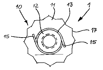
Figure 1 a schematic, not dimensionally true representation of the invented
lock nut in top view, and
Figure 2 a schematic, not dimensionally true representation of the lock nut of
figure 1, in cross section.
An example of embodiment of the invented lock nut is schematically depicted in
figures 1 and 2. The lock nut 1 consists of a nut body 10, which has a large
flange 11. From the flange 11 there extends a neck projection 12 in axial
direction. On the end surface 14 of the neck projection 12 is formed an
annular
shroud 13, which likewise extends in axial direction.
In the example of embodiment shoHm for the lock nut 1, the outer diameter of
the
neck projection 12 and the outer diameter of the annular shroud 13 are of the
same dimension. Two opposite claws 15 are punched out from the annular
shroud 13 and bent radially outward.

CA 02408079 2002-10-15
6
These claws 15 engage with the splining formed between the flange and the
universal shaft to secure the lock nut 1. In the example of embodiment, the
claws
15 are configured as lobes extending tangentially away from the annular shroud
13. Any other suitable configuration and arrangement for the claws '! 5 is
also
conceivable.
For screwing together and achieving optimal clamping force, the lateral
surface
of the flange i 1 is provided with a toothing 17, which can engage with an
installation tool. The toothing 17 can be hexagonal, or also finrelve-point,
as in the
example of embodiment.
With the invented lock nut 1, a reliable and secure fastening of a flange onto
a
universal shaft, such as a wheel flange, as described in patent DE 195 43 436
C2, is possible under cost-effective conditions. At the same tine, the
invented
lock nut 1 keeps moisture out from the inside of the bearing. Furthermore,
with
the invented lock nut the required bearing prestressing force can be produced
and maintained, if the bearing design requires such in the particular
application.

Dessin représentatif
Une figure unique qui représente un dessin illustrant l'invention.
États administratifs

2024-08-01 : Dans le cadre de la transition vers les Brevets de nouvelle génération (BNG), la base de données sur les brevets canadiens (BDBC) contient désormais un Historique d'événement plus détaillé, qui reproduit le Journal des événements de notre nouvelle solution interne.

Veuillez noter que les événements débutant par « Inactive : » se réfèrent à des événements qui ne sont plus utilisés dans notre nouvelle solution interne.

Pour une meilleure compréhension de l'état de la demande ou brevet qui figure sur cette page, la rubrique Mise en garde , et les descriptions de Brevet , Historique d'événement , Taxes périodiques et Historique des paiements devraient être consultées.

Historique d'événement

Description Date
Demande non rétablie avant l'échéance 2008-10-15
Le délai pour l'annulation est expiré 2008-10-15
Réputée abandonnée - omission de répondre à un avis sur les taxes pour le maintien en état 2007-10-15
Inactive : Abandon.-RE+surtaxe impayées-Corr envoyée 2007-10-15
Inactive : CIB de MCD 2006-03-12
Demande publiée (accessible au public) 2003-04-30
Inactive : Page couverture publiée 2003-04-29
Lettre envoyée 2003-02-11
Modification reçue - modification volontaire 2003-01-20
Inactive : Transfert individuel 2002-12-17
Inactive : CIB en 1re position 2002-12-17
Inactive : Lettre de courtoisie - Preuve 2002-12-10
Inactive : Certificat de dépôt - Sans RE (Anglais) 2002-12-03
Exigences de dépôt - jugé conforme 2002-12-03
Demande reçue - nationale ordinaire 2002-12-02

Historique d'abandonnement

Date d'abandonnement Raison Date de rétablissement
2007-10-15

Taxes périodiques

Le dernier paiement a été reçu le 2006-10-13

Avis : Si le paiement en totalité n'a pas été reçu au plus tard à la date indiquée, une taxe supplémentaire peut être imposée, soit une des taxes suivantes :

  • taxe de rétablissement ;
  • taxe pour paiement en souffrance ; ou
  • taxe additionnelle pour le renversement d'une péremption réputée.

Veuillez vous référer à la page web des taxes sur les brevets de l'OPIC pour voir tous les montants actuels des taxes.

Historique des taxes

Type de taxes Anniversaire Échéance Date payée
Taxe pour le dépôt - générale 2002-10-15
Enregistrement d'un document 2002-12-17
TM (demande, 2e anniv.) - générale 02 2004-10-15 2004-10-14
TM (demande, 3e anniv.) - générale 03 2005-10-17 2005-08-24
TM (demande, 4e anniv.) - générale 04 2006-10-16 2006-10-13
Titulaires au dossier

Les titulaires actuels et antérieures au dossier sont affichés en ordre alphabétique.

Titulaires actuels au dossier
METALLWARENFABRIK HERMANN WINKER GMBH & CO., KG
Titulaires antérieures au dossier
ALEXANDER WINKER
Les propriétaires antérieurs qui ne figurent pas dans la liste des « Propriétaires au dossier » apparaîtront dans d'autres documents au dossier.
Documents

Pour visionner les fichiers sélectionnés, entrer le code reCAPTCHA :


Pour visualiser une image, cliquer sur un lien dans la colonne description du document. Pour télécharger l'image (les images), cliquer l'une ou plusieurs cases à cocher dans la première colonne et ensuite cliquer sur le bouton "Télécharger sélection en format PDF (archive Zip)" ou le bouton "Télécharger sélection (en un fichier PDF fusionné)".

Liste des documents de brevet publiés et non publiés sur la BDBC .

Si vous avez des difficultés à accéder au contenu, veuillez communiquer avec le Centre de services à la clientèle au 1-866-997-1936, ou envoyer un courriel au Centre de service à la clientèle de l'OPIC.


Description du
Document 
Date
(aaaa-mm-jj) 
Nombre de pages   Taille de l'image (Ko) 
Description 2002-10-15 6 204
Abrégé 2002-10-15 1 12
Revendications 2002-10-15 2 43
Dessins 2002-10-15 1 14
Dessin représentatif 2003-01-08 1 7
Page couverture 2003-04-04 1 32
Certificat de dépôt (anglais) 2002-12-03 1 159
Courtoisie - Certificat d'enregistrement (document(s) connexe(s)) 2003-02-11 1 107
Rappel de taxe de maintien due 2004-06-16 1 109
Rappel - requête d'examen 2007-06-18 1 118
Courtoisie - Lettre d'abandon (requête d'examen) 2007-12-24 1 167
Courtoisie - Lettre d'abandon (taxe de maintien en état) 2007-12-10 1 175
Correspondance 2002-12-03 1 24