Note: Descriptions are shown in the official language in which they were submitted.
CA 02408168 2002-11-05
WO 01/86218 PCT/1B01/01027
1
APPARATUS AND METHODS FOR COOLING AND LIQUEFYING A
FLUID USING MAGNETIC REFRIGERATION
Field of the Invention
The invention pertains to methods and apparatus for liquefying cryofuels.
Background of the Invention
Cryogenic liquefaction of gases can be accomplished through a variety of
methods, some involving mechanical cycles with gaseous refrigerants, others
making use of cycles using the thermodynamic properties of magnetic materials.
Gases such as hydrogen and natural gas are commonly liquefied by processes
in which the gas to be liquefied, also called the process stream, is used as
the
working fluid in a mechanical cycle such as the Claude cycle, Linde cycle, or
Brayton cycle, involving compression and subsequent expansion of the working
fluid. Various implementations of the Claude cycle into liquefiers have
achieved a
maximum relative efficiency or figure of merit of about 37%. A figure of merit
(FOM) is a ratio of the ideal miniinum work that must be supplied to liquefy a
quantity of a gas to the actual work that is supplied to liquefy the same
quantity of
the gas. The ideal work differs for each fluid that is liquefied.
Liquefiers can also have a,ivorking fluid loop separate from the process
stream. In such devices, the working fluid or refrigerant is separate from the
process
stream fluid. The cooling provided by the refrigerants in a thermodynamic
cycle
cools and eventually liquefies the process stream fluid. The coupling between
the
process stream and working fluids is normally accomplished by one or more heat
exchangers. A regenerative magnetic refrigerator that operates as a liquefier
is an
example of this type of liquefier, where the process stream is separate from
the
refrigerant.
A regenerative magnetic refrigerator uses working materials such as
magnetic solids whose magnetic order or magnetic entropy depends on
temperature
and applied magnetic field. With such a magnetic refrigerant, cooling is
CA 02408168 2002-11-05
WO 01/86218 PCT/1B01/01027
2
accomplished by a mechanical cycle as follows: The magnetic refrigerant is
adiabatically placed in a magnetic field. The conservation of total entropy in
this
adiabatic process requires that the refrigerant increase in temperature to
compensate
for the increased order in the magnetic moments or decrease in magnetic
entropy of
the magnetic refrigerant due to the external magnetic field. This temperature
change
is sometimes called the adiabatic temperature change and it can be used to
transfer
heat to a thermal sink with a corresponding decrease in refrigerant
teinperature. The
magnetic refrigerant is then removed adiabatically from the magnetic field,
producing a corresponding temperature decrease. This temperature decrease can
be
used to accept heat from a thermal load with a corresponding material
temperature
increase. (The change in temperature of a magnetic material that occurs as a
result
of an adiabatic change in externally applied magnetic field is called the
magnetocaloric effect.) The magnitude of this temperature change is typically
about
2 Kper Tesla or a total of about 10 -15 K for 5- 6 T. To increase the
temperature
span between the average hot temperature or thermal-sink temperature, and
average
cold temperature or thermal-load temperature, it is normal to use regenerative
steps
in the cycle. Thus, the basic regenerative magnetic cycle consists of:
adiabatic
temperature increase upon magnetization; heat transfer to a thermal sink;
regenerative heat transfer to decrease the magnetized magnetic refrigerant
average
temperature; adiabatic temperature decrease upon demagnetization; heat
transfer
from the thermal load; and regenerative heat transfer to increase the
demagnetized
magnetic refrigerant average temperature back to the starting temperature of
the
cycle. Such regenerative magnetic cycles, where the regenerative function of
the
cycle is accomplished by the solid working magnetic refrigerant, are called
active
magnetic regenerative cycles. Refrigerators based on such cycles are called
active
magnetic regenerative refrigerators. Active magnetic regenerative
refrigerators
(AMRRs) can be used as liquefiers (active magnetic regenerative liquefiers
"AMRLs")) to cool a process stream.
Prior art magnetic refrigeration systems for liquefying gases present the
following drawbacks:
1) high magnetic fields are required for efficient refrigeration;
CA 02408168 2002-11-05
WO 01/86218 PCT/1B01/01027
3
2) superconducting magnets in Helmholtz configurations, used in some
embodiments of magnetic refrigerators to produce the necessary magnetic
fields, are expensive;
3) immersion cooling of superconducting magnets with liquid helium is
difficult and expensive;
4) design and construction of high-performance, multi-material magnetic
regenerators required for optimal, reliable, long-lived active magnetic
regenerative devices with brittle magnetic refrigerants is difficult;
5) design of housings to contain heat-transfer fluids and to control the flow
of
these fluids through magnetic regenerators with reliable sealing mechanisms
is difficult;
6) there are intrinsic limitations on the FOM of various configurations of
multistage refrigerators for the purpose of gradually cooling and liquefying a
process stream; and
7) high frequency, high efficiency operation has not been achieved.
Summary of the Invention
In view of the shortcomings of the prior art, the present invention provides,
inter alia, active magnetic regenerative refrigerator (AlVIRR) systems
including one
or more of the following features:
(a) increased efficiency through the use of multiple-stage active regenerative
magnetic refrigerators with an external process stream to achieve liquefaction
of a
gas, instead of a gas cycle that uses the process stream as the working fluid;
(b) increased efficiency through a parallel or series-parallel configuration
of
multiple refrigeration stages, that effectively pump heat from a thermal load
in a
process stream to a hot bath at room temperature or other common thermal sink
temperature;
(c) increased overall efficiency by recognition that a mathematical
optimization of cold temperatures for each stage can permit the total work
.30 performed by a multistage liquefier to be reduced;
CA 02408168 2002-11-05
WO 01/86218 PCT/1B01/01027
4
(d) increased efficiency through an ortho-para catalysis of the process
stream continuously as a process stream is cooled;
(e) efficient coupling of a magnetic refrigerant and a heat-transfer fluid in
a
porous regenerator matrix composed of selected magnetic materials configured
in
geometries to reduce entropy generation;
(f) for each stage or selected stages, an admixture of magnetic materials
comprising the magnetic refrigerants, wherein the admixture is optimized or
otherwise configured for a particular operating temperatures of that stage;
(g) counterflow heat exchangers for each refrigeration stage (or selected
stages), allowing additional cooling of a process stream with a portion of a
regenerator heat-transfer fluid as the fluid is returned to room temperature
in parallel
with flow through the regenerators, thus allowing a greater utilization of the
heat-
transfer fluid for more efficient cooling of the process stream (such "fluid
bypass" of
the regenerator is effective because the thermal mass of a magnetic
regenerator can
be configured to be lower in a higher magnetic field than in a lower magnetic
field,
so that there is more flow from hot to cold than from cold to hot in a
balanced flow
regenerator);
(h) in multiple-stage systems, an arrangement of inexpensive, solenoidal,
superconducting magnets configured with alternating magnetic field directions
that
simultaneously enhances core fields in the solenoids and provides a magnetic
flux
return path for adjacent solenoids reducing stray magnetic fields;
(i) a hexagonal configuration of superconducting magnets in a six-stage
embodiment;
(j) conductively cooled superconducting magnets using a multistage, small
capacity cryocooler;
(k) a sealing arrangement and housing configuration such that a small,
controlled leakage of heat-transfer fluid occurs as heat-transfer fluid flow
is directed
tlzrough the moving regenerators segments; and
(1) a stage comprising an active magnetic regenerative refrigeration (AMRR)
device that includes a linked chain or conveyor belt of magnetic refrigerating
regenerators or segments, constructed of magnetic materials with tunable
ordering
CA 02408168 2007-08-13
temperatures that withstand repeated thermal stress due to heating and
cooling, while
remaining intact and functional.
In one embodiment, the invention provides an active magnetic regenerative
liquefier (AMRL), comprising: at least a first and a second active magnetic
5 refrigerators (AMRRs), the first AMRR configured to receive and cool a
process
stream, and deliver the process stream to the second AMRR, wherein the first
and
second AMRRs have respective thermal reservoirs at a common temperature.
In a further embodiment, the invention provides a hydrogen liquefier,
comprising: at least three active magnetic regenerator refrigerators (AMRRs)
situated
and configured to receive and serially cool a hydrogen process stream; and at
least two
ortho to para convertors situated between at least two of the AMRRs.
In a further embodiment, the invention provides a liquefier, comprising an at
least six magnetic cooling stages, wherein the cooling stages are situated and
configured to receive a magnetic field from a hexagonal array of solenoids
that
includes a frame that is configured to conduct respective magnetic fluxes
produced by
the solenoids.
Methods and apparatus according to the invention allow, inter alia, cooling of
a
gas, such as hydrogen or natural gas, to the point of liquefaction utilizing
refrigeration by
adiabatic magnetization/demagnetization of selected solid magnetic
refrigerants in an active
magnetic regenerative cycle.
The foregoing and additional features and advantages of the present invention
will be more readily apparent from the following detailed description, which
proceeds
with reference to the drawings.
Brief Description of the Drawings
FIG. 1(A) is a schematic vertical section of a first representative embodiment
of an
active magnetic regenerative refrigerator (AMRR).
FIG. 1(B) is an isometric schematic representation of certain operational
aspects
of the AMRR of FIG 1(A).
FIG. 2 is a schematic diagram of a second representative embodiment of an AMRR
according to the invention.
FIGS. 3(A) and 3(B) are schematic horizontal and vertical sections,
respectively,
of a superconducting magnet array comprising six superconducting magnets, each
of
which is used in an AMRR such as that in FIG. 1.
FIG. 4 is a schematic elevational diagram of a representative cryocooler for
cooling
a superconducting magnet assembly.
CA 02408168 2007-08-13
5a
FIG. 5 is a schematic diagram of a representative embodiment of a parallel
configuration of a six-stage liquefier according to the invention.
FIG. 6 is a schematic diagram of a series-parallel configuration of a six-
stage
liquefier.
Detailed Description of the Invention
FIGS. 1(A) and 1(B) depict certain aspects of a stage 100 of an active
magnetic
regenerative refrigerator (AMRR) according to a first representative
embodiment. As
shown in FIG. 1(A), the AMRR stage 100 comprises multiple
CA 02408168 2008-07-23
6
regenerative magnetic refrigerating segments ("segments") 102 mounted on a
flexible
conveyor belt 108 that is driven by rollers 114 or other supports. The
segments 102
comprise a magnetic refrigerant, or a mixture of magnetic refrigerants,
embedded in a
porous matrix that allows a heat-transfer fluid, directed at the matrix, to
pass through
the segments 102.
A portion ("hot-blow zone") 106, of a path traversed by the segments 102 as
moved by the conveyor belt 108 is surrounded by a superconducting magnet 104.
In
the hot-blow zone 106, heat is released by the segments 102 that have a higher
average temperature due to adiabatic magnetization of the magnetic
refrigerants in a
strong magnetic field produced by the superconducting magnet 104. As shown in
FIG. 1(B), the released heat is delivered to an external heat sink by a heat-
transfer
fluid 116 that flows through the segments 102 that are situated in the hot-
blow zone
106.
A portion "cold-blow zone" 109 of the path traversed by the segments 102 is
situated outside a high magnetic field region and the hot-blow zone 106. The
segments 102 exit the hot-blow zone 106, pass through a no-flow zone, and then
enter
the cold-blow zone 109. The cold-blow zone 109 is a region of low applied
magnetic
field where the segments 102 are colder due to adiabatic demagnetization in
the no-
flow zone. In the cold-blow zone 109, the segments 102 absorb heat from the
heat-
transfer fluid 116 that is directed through the segments 102.
As the segments 102 move along directions 110, the segments 102 enter the
hot-blow zone 106 produced by the superconducting magnet 104. In a no-flow
zone
wherein no heat-transfer fluid passes through the segments, prior to the
segments 102
entering into the hot-blow zone 106, the magnetic field tends to align the
magnetic
moments of the magnetic refrigerant(s) within each segment 102 along a
magnetic
field direction of the magnetic field produced by superconducting magnet 104.
As a
result of such alignment, along the long axis of the regenerative segment
comprising
one or more magnetic materials in the no-flow zone, the magnetic refrigerants
increase in temperature through an adiabatic temperature change for each of
the
respective magnetic materials. Typically, the segments 102 include one or more
magnetic materials that are configured so that a composition of the segments
102
varies along an axis 150.
As shown in FIGS. 1(A)-1(B), the hot-blow zone 106 is defined by a duct 111
that directs the heat-transfer fluid 116 (e. g., helium or other fluid)
through the
CA 02408168 2008-07-23
7
segments 102 within the duct 111 so that the heat-transfer fluid 116 absorbs
heat from
the segments 102. The heat-transfer fluid 116 is then circulated to a hot
reservoir (not
shown) where the heat-transfer fluid 116 releases the heat that was absorbed
through
thermal contact with the segments 102.
After passing through the hot-blow zone 106, the segments 102 enter the no-
flow zone of reduced magnetic field, and the cold-blow zone 109. In the cold-
blow
zone 109, the magnetic field is substantially less than that of the hot-blow
zone 106.
In the no-flow zone, adiabatic demagnetization of the magnetic refrigerant in
the
segments 102 occurs. Adiabatic demagnetization results in accompanying
temperature drops throughout the segments 102. A duct 112 in the cold-blow
zone
109 directs the heat-transfer fluid 116 through the porous magnetic
refrigerating
segments 102 passing through the duct 112. The heat-transfer fluid 116 is
cooled by
contact with the segments 102 near the coldest temperature of the particular
stage of
the multistage liquefier. After passing through the cold-blow zone 109, the
resulting
cooled heat-transfer fluid 116 is then brought into thermal contact with a
process
stream (not shown) in a process heat exchanger, cooling the process stream.
The conveyor belt 108 is constructed of a material capable of withstanding the
stress of repeated temperature oscillations and other cyclic magnetic-related
stresses.
By way of example, one suitable material is #316 stainless steel. On the
conveyor
belt 108, the segments 102 are arranged in a regular matrix of multiple rows.
For
example, as shown in FIG. 1(B), each row contains four segments 102. Also, by
way
of example, each segment 102 shown in FIG. 1(B) is orthorhombic (brick-like)
in
shape.
The optimal size of the segment 102 is selected by minimizing the generation
of entropy from several mechanisms such as heat transfer, pressure drop of the
heat-
transfer fluid, thermal conduction along the long axis of the regenerative
segment, and
eddy current heating. The typical axial length to facial dimension aspect
ratio of the
segment from this analysis is approximately 3 to 1. The linear dimension of
the face
of the orthorhombic segment may be of order of one inch or more and the
surfaces of
the segments 102 are configured to seal the heat transfer fluid within the
duct and
regenerator.
Representative geometries of the magnetic refrigerants include particles
approximately 100-200 micrometers in diameter, fine wires, or thin, closely
spaced
sheets. However, any of various other sizes and/or shapes can be used as
conditions
CA 02408168 2008-07-23
8
of use indicate. Each segment 102 comprises at least one magnetic refrigerant
material (desirably an appropriately layered admixture of more than one such
material) combined in a monolithic, high strength matrix. For example,
International
Application No. PCT/US97/18059 (International Publication No. WO 98/28585),
teaches one method of combining brittle magnetic refrigerants into a
monolithic
regenerative segment. Typical magnetic refrigerants include relatively ductile
rare
earth elements and alloys such as Gd, Dy, GdXDyl_X, GdXHoI_X, TbXDyI_X,
brittle
intermetallic compounds such as Gd5 (SiXGeI_X)4, GdZn, GdNi2, DyA12, ErA12,
and at
temperatures below about 20 K, dielectric magnetic compounds such as
Gd3Ga50l2.
U. S. Patent 5,887,449 to Pecharsky and Gshneidner, teaches an active magnetic
refrigerant comprising DyA12 and a low-temperature stage including an active
magnetic refrigerant comprising (Dyl_X ErX)A12, wherein x is selected to be
greater
than about 0.5 and less than 1 so as to be rich in erbium. An alternative high-
temperature-stage active magnetic refrigerant may comprise (Dyl_X ErX)A12
where x is
selected to be greater than 0 and less than about 0.3. A preferred low-
temperature-
stage active magnetic refrigerant comprises (Dy, _X ErX)A1 Z, wherein x is
selected to be
from about 0.6 to about 0.9. U. S. Patent 5,743,095 to Gshneidner, Jr. et al.,
provides
an active magnetic regenerator and method that use a magnetic refrigerant Gd5
(Six
Gel_X)4 where 0<_ x<_ 0.55. The segments 102 can include such intermetallic
compounds, other similar compounds, as well as compounds of other rare earth
materials.
The magnetic refrigerants are typically selected to have ordering temperatures
close to their operational temperatures. For example, in a multistage
CA 02408168 2002-11-05
WO 01/86218 PCT/1B01/01027
9
series-parallel configuration of a magnetic liquefier for hydrogen, the
various stages
span temperatures from less than about 20 K to about 300 K. Each regenerative
segment on the corresponding rotating chain in that stage of the AMRR operates
over a limited temperature range near its particular ordering temperature
where its
adiabatic temperature change is largest and most easily accomplished by the
action
of the applied magnetic field. Each magnetic refrigerant typically operates
most
efficiently over a temperature range of about 20-40 K from the ordering
temperature
and below the ordering temperature so that each AMRR stage typically has
segments with 2-10 or more different magnetic materials. A stage operating
from
about 260 K to about 300 K typically requires only one magnetic refrigerant.
The
exact makeup and arrangement of the segments 102 depend upon, inter alia, the
temperature span of the refrigeration stage in which the particular AMRR is
intended to be used.
The heat-transfer fluid 116 is a substance, typically a gas such as helium,
having heat-transfer characteristics that permit efficient transfer of heat
between the
heat-transfer fluid 116 and the segments 102, as well as efficient heat
transfer
between the heat-transfer fluid 116 and the process stream (not shown).
In a first representative embodiment, the segments 102 are compactly and
reliably attached to the conveyor belt 108. As the conveyor belt 108 moves
around
the supports or rollers 114 the conveyor belt 108 bends, and the segments 102
that
are attached to the conveyor belt 108 partially separate and come tightly back
together again. The heat-transfer fluid flows primarily through the segments,
rather
than between or over or under the segments in the hot-blow or cold-blow zones.
The heat-transfer fluid is prevented from flowing in the no-flow zones of the
cycle.
The sealing mechanism includes a primary seal that is a spring-loaded frontal
facial
seal of a low friction, wear resistant material such as RULONTM, TEFLONTM, or
tetrafluoroethylene, or other fluoropolymer loaded with graphite or other
toughening
materials that contacts ends of the magnetic segments that are tightly fitted
together
with a thin sealing material between them. The tops and bottoms of the
segments
102 also have seals that fit into the housing and lightly contact the segments
102 on
the conveyor belt 108.
CA 02408168 2002-11-05
WO 01/86218 PCT/1B01/01027
The AMRR shown in FIG. 1(A) can be regarded as a single refrigerator
"stage." An active magnetic regenerative liquefier (AMRL) typically comprises
multiple AMRR stages configured so that each stage is configured for cooling
an
AMRR process stream in a selected temperature range. By way of example, as
5 noted below, an AMRL, according to the invention, can comprise six AMRR
stages,
each with corresponding hot-blow zones 106, no-blow zones 118, 122, cold-blow
zones 109, ducts 111, 112, conveyor belt 108, and array of magnetic
refrigerating
segments 102. In each stage, the superconducting magnet 104 can comprise a
respective coil of superconducting wire, or solenoid, mounted on a support
structure.
10 In an example refrigeration system that includes multiple stages (e.g., six
stages), the
superconducting magnet is configured as a corresponding array of the
respective
coils of superconducting wire on the support structure. Each coil provides a
respective region of high magnetic field for the respective stage of
refrigeration In a
series-parallel multiple-stage refrigerator system, according to the
invention, the
lower stages have the next higher cold temperature as the hot temperature
reservoir
temperature and higher stages have the same hot reservoir temperature, usually
room
temperature, about 300 K.
Referring furtller to FIG. 1(B), a representative magnetic segment 153
includes subsegments 154-156 that are selected based on a temperature range
anticipated in the segment 153. Typically the subsegments are selected to
obtain a
relatively higher thermal mass in a low or zero magnetic field, and a lower
thermal
mass in a higher magnetic field. In alternative embodiments, the segments 102
can
be layered or graded magnetic refrigerants.
FIG. 2 schematically depicts a second embodiment of a refrigerator stage. A
25. magnetic material 210, e.g., an ordered magnetic substance bound in a
matrix, is
configured on a rotating drum or wheel 214. A motor 216 rotates the drum 214
about an axis (rotation denoted by arrow 207). A process stream at a starting
temperature, e.g., room temperature, enters at an inlet 202. The process
stream exits
at (or below) its condensation temperature at an outlet 226. A first heat
exchanger
204 removes heat from the process stream. A pump 222 propels a first heat-
transfer
fluid 206 (e.g., helium) through the first heat exchanger 204, thereby
conducting
CA 02408168 2002-11-05
WO 01/86218 PCT/1B01/01027
11
heat away (arrow 201) from the first heat exchanger. The first heat-transfer
fluid
206 then flows through a hot-blow zone 208 where the first heat-transfer fluid
206
removes heat (arrows 209) from an ordered magnetic materia1210 situated in a
region (ellipse 203) of high magnetic field supplied by a magnetic coi1212
that
surrounds a portion of the rotating drum 214. The first heat-transfer fluid
206 then
flows through a second heat exchanger 218 that removes heat from the first
heat-
transfer fluid 206 and expels the heat (arrow 205) to a hot reservoir (not
shown) via
a second heat-transfer fluid, which enters the second heat exchanger 218 at an
inlet
220, and exits at an outlet 222. The first heat-transfer fluid 206 then flows
through a
cold-blow zone 228, a region of reduced magnetic field where the ordered
magnetic
material present in the cold-blow zone 228 is reduced in temperature due to
adiabatic demagnetization. Here, additional heat is removed (arrows 211) from
the
first heat-transfer fluid 206 by the ordered magnetic materia1210. Between the
hot-
blow zone 208 and cold blow zone 228 are "no-flow zones" 213a, 213b in which
substantially no heat flow occurs.
FIG. 3(A) depicts a representative embodiment of a superconducting magnet
array 300 that supplies the respective magnetic fields to a set of six AMRR
stages.
This arrangement of superconducting coils can also be used to supply magnetic
field
in an embodiment of, for instance, less than six AMRR stages. It is possible,
for
instance, for one AMRR stage to use one solenoid for a portion of the conveyor
belt
travelling in one direction, and a second solenoid for another portion of the
conveyor
belt travelling in the opposite direction, and so have six solenoids for three
stages.
Also, the total number of coils can, for instance, be reduced.
The superconducting magnet array 300 shown comprises six
superconducting solenoidal magnet coils 302, each centered at a vertex 304 of
a
hexagon. The direction of the field of each coil 302 is opposite to the
direction of
the respective fields of each of the two adjacent coils 302. A support
structure 306
supports the coils 302 in their proper orientation and position relative to
each other,
and provides a magnetic-flux return path and a thermal bus for the entire
array.
FIG. 3(B) is a side view of a portion of the superconducting magnetic array
of FIG. 3(A), showing the support structure 306 and (in this view) two
CA 02408168 2002-11-05
WO 01/86218 PCT/1B01/01027
12
superconducting solenoidal magnetic coils 302a, 302b, respectively. The
support
structure 306 is constructed of, e.g., soft iron, to provide a flux-return
path and a
heat-conduction path to conductively cool the superconducting magnetic array.
Each of the six superconducting magnet coils 302 surrounds a respective
conveyor-
belt AMRR stage (such as the embodiment of FIG. 1(A)), thereby providing the
region of high magnetic field to the respective AMRR stage. Also shown in FIG.
3(B) are respective orientations of the magnetic coils 302a, 302b and
respective
directions (arrows 308a, 308b) of the magnetic fields B. As can be seen, the
magnetic-field direction alternates for each adjacent superconducting
solenoidal
magnet coil 302. According to alternative embodiments, two, four, six, eight
or
other even number solenoids can be arranged to provide a suitable magnetic
field.
FIG. 4 depicts a representative embodiment of a cryostat 400 for maintaining
a superconducting magnetic array at, for example, 4.2 K. The superconducting
magnetic array is situated in an inner chamber 402 of the cryostat 400. In the
inner
chamber 402, the superconducting magnetic array is cooled to the desired
temperature by a two-stage cryo-cooler 404 sucli as, for exainple, a pulse
tube or
Gifford McMahon device. Electrical power is supplied to the superconducting
magnet array via a feed-through 406. Once the magnets are fully charged, they
can
be put into persistent mode and the power supply turned off. A removable cover
408 permits accessibility to the interior of the cryostat 400. Conduits for
instrumentation and magnet control are routed into the cryostat 400 via a feed-
through 410. A drive feed-through 412 provides access into the cryostat for
the
drive motors that actuate the respective conveyor belt(s) for each stage. A
vacuum-
insulation chamber 428 of the cryostat 400 is evacuated via a vacuum port 414.
A
feed-tlirough 416 provides a conduit into the cryostat 400 of the heat-
transfer fluid to
permit the heat-transfer fluid to circulate through the respective regions of
high
magnetic field. A process-stream input feed-through 418 allows access of the
process stream, to be cooled, into the cryostat. The process stream exits the
cryostat
400 through an output feed-through 420. A vacuum-tight housing 422 encases the
entire cryostat 400. The inner chamber 402 desirably is supported in the
housing
422 by supports 424, constructed of a material (e.g., fiberglass) having low
thermal
CA 02408168 2002-11-05
WO 01/86218 PCT/1B01/01027
13
conductivity. A thermal shield 426 is situated between the inner chamber 402
and
the housing 422. The thermal shield is maintained at a temperature of, e.g.,
40 K, so
as to thermally insulate the inner chamber 402 from the external environment.
FIG. 5 depicts a six-stage AMRR system 500 according to a representative
embodiment of such a system according to the invention. A process stream 502
(e.g., hydrogen) enters the system 500 from the right in the figure. By way of
example, the initial temperature of the process stream is room temperature,
e.g.,
approximately 300 K.
The system 500 comprises six AMRR stages 504, 514, 516, 518, 520, 522.
Each of the six AMRR stages has a respective hot reservoir 512. In a parallel
configuration of stages, the hot-reservoir temperatures are equal (e.g.,
approximately
300 K, or room temperature). An improved or optimum figure of merit (FOM) of
the overall system can be realized by parametric analysis of the individual
stages
based on practically achievable efficiencies to determine optimal or near-
optimal
coldest temperatures for the respective AMRR stages. This determination is
done by
calculating the total work from six refrigeration stages pumping heat from a
separate
process stream (the heat loads depend upon temperature, pressure, mass flow
rate,
and the particular fluid) from a respective set of six cold temperatures to a
respective
set of hot reservoir temperatures. The total work input is reduced by
searching
through the set of all combinations of the stage temperatures with approximate
stage
efficiencies and the associated heat loads for a given process stream. The
stage
efficiencies are then refined and the calculation repeated. If desired, the
calculation
can be refined and repeated until calculation efficiencies converge to an
optimum or
desired value.
By way of example, respective output temperatures of the six stages each
with 100% efficiency, as used to liquefy hydrogen at a pressure of -0.1 MPa,
are as
follows: the first AMRR stage 504 has a cold-reservoir temperature of 192 K;
the
second AMRR stage 514 has a cold-reservoir temperature of 120 K; the third
AMRR stage 516 has a cold-reservoir temperature of 78 K; the fourth AMRR stage
518 has a cold-reservoir temperature of 48 K; the fifth .AMRR stage 520 has a
cold-
reservoir temperature of 32 K; and the sixth AMRR stage 522 has a cold-
reservoir
CA 02408168 2002-11-05
WO 01/86218 PCT/1B01/01027
14
temperature of 20 K. At each stage, a respective bypass-flow-control valve 524
permits counter-current heat exchange of the heat-transfer fluid with the
process
stream in a respective bypass fluid heat exchanger 534, thereby considerably
increasing the efficiency with which the process stream is cooled.
Passive regenerators can be fabricated of materials with very large thermal
masses such that in normal operation, the thermal mass does not change. In
balanced regenerator operation, the heat-transfer fluid flow is the same in
the cold-
blow and hot-blow zones of the regenerator. In an active magnetic regenerator,
the
thermal mass of the respective magnetic refrigerants near their respective
ordering
temperatures changes due to the effects of the magnetic field. The respective
differences in thermal mass of the magnetic regenerator materials below their
respective ordering temperature within and outside of the magnetic field,
allow more
heat-transfer fluid to flow in the hot-blow zone than in the cold-blow zone.
The
difference in flows may be of order ten per cent of the average total
regenerator
heat-transfer fluid flow. This excess cold heat-transfer fluid can be returned
via
external heat exchangers that further cool the process stream in a continuous
flow,
thereby significantly increasing the thermodynamic efficiency of the
liquefier.
For cooling of hydrogen, a continuous orthopara catalytic converter 528 is
associated with each A.MRR stage to convert the process stream to an
equilibrium
concentration of the para form of hydrogen at that particular temperature. By
doing
this conversion continuously the efficiency of the liquefier is significantly
increased.
After passing through the sixth stage of refrigeration, the process-stream
output 530
is, e.g., liquid hydrogen at 20 K. An external cooling fluid, supplied at an
inlet 526,
removes heat from the respective hot reservoirs 512 that are at or near room
temperature. A cooling-fluid return outlet 532 routes the cooling fluid for
heat
removal (using an apparatus not shown) and subsequent return to the inlet 526.
As the process stream 502 proceeds through each AMRR stage, the process
stream is cooled to the respective temperature for that stage. Within each
AMRR
stage the respective conveyor belt (not shown in FIG. 5, but see FIG. 1(A)) is
continually moving, routing the respective magnetic refrigerating segments
through
a respective region of high magnetic field. As the segments pass through the
hot-
CA 02408168 2002-11-05
WO 01/86218 PCT/1B01/01027
blow region, heat is transferred from the magnetic refrigerants to the heat-
transfer
fluid as the heat-transfer fluid passes through the porous regenerator
segments. The
heat-transfer fluid is conducted to the respective hot reservoirs or thermal
sinks,
where the heat-transfer fluid'releases the heat to the hot reservoirs or
thermal sinks.
5 The heat-transfer fluid is then routed back to the magnetic refrigerating
segments that are passing through the respective region of low magnetic field.
As
the segments move from the high field region to the low field region, they
undergo
an adiabatic demagnetization (with no flow of heat-transfer fluid); hence each
magnetic material decreases in temperature by the adiabatic temperature change
for
10 the respective material at its operating temperature. In the region of low
magnetic
field, the heat-transfer fluid passes from hot to cold in each segment and is
cooled to
below the average cold temperature for the respective segment. The heat-
transfer
fluid is then routed to absorb heat from the process stream. A portion of the
cold
heat-transfer fluid can be routed to respective bypass-fluid heat exchangers,
15 producing further cooling of the process stream.
The process stream then continues to the next (downstream) AMRR stage of
refrigeration, e.g., from the first stage 512 to the second AMRR stage 514
where the
process stream is cooled to the next lower temperature. At the final stage of
refrigeration (e.g., in the sixth stage 522), a latent heat of vaporization
can be
removed, liquefying the process stream.
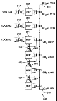
With reference to FIG. 6, an AMRL 600 includes AMRR stages 602-607 that
are configured to deliver liquid hydrogen at a temperature of about 20 K to an
output
610. Hydrogen gas at a temperature of approximately 300 K is delivered to an
input
612 and the to the AMR.R stages 602-607. The configuration of the AMRL 600 is
a
series-parallel configuration in that the AMRR stages 602-604 have thermal
reservoirs 612 that are at a common temperature, and the AMRR stages 604-606
are
configured to provide respective thermal reservoirs 622, 623, 624 for
respective
downstream AMRR stages 605-607. Stage temperatures for the AMRL 600 are
300, 201 K, 90 K, 60 K, 40 K, and 20 K suitable for liquefying of hydrogen at
a
pressure of about 0.5 MPa. In addition, additional heat exchangers, ortho-para
CA 02408168 2002-11-05
WO 01/86218 PCT/1B01/01027
16
converters, and fluid bypass components are not shown in FIG. 6, but can be
similar
to those of FIG. 5.
Whereas the invention has been described in connection with representative
embodiments, it will be understood that the invention is not limited to those
embodiments. On the contrary, the invention is intended to encompass all
modifications, alternatives, and equivalents as may be included within the
spirit and
scope of the invention, as defined by the appended claims.