Note: Descriptions are shown in the official language in which they were submitted.
CA 02408325 2002-11-07
- 1 -
METHOD AND DEVICE FOR TREATING A C4 FRACTION
The present invention relates to a process for isolating 1,3-butadiene by work-
up of
a C4 fraction and to an apparatus for carrying out the process. The C4
fraction
obtained in crackers, is a mixture of hydrocarbons in which C4-hydrocarbons,
in
particular 1-butene, i-butene and 1,3-butadiene, predominate. Apart from small
amounts of C3- and C5-hydrocarbons, the C4 fraction generally further
comprises
C3- and C4-acetylenes, for example 1-butyne, butenyne and propyne, in
particular
1 -butyne (ethylacetylene) and butenyne (vinylacetylene).
The isolation of 1,3-butadiene from such mixtures represents a complicated
distillation problem because of the small differences in the relative
volatilities.
Fractionation is therefore carried out by extractive distillation, i.e.
distillation with
addition of an extractant which has a boiling point higher than that of the
mixture
to be fractionated and increases the differences in the relative volatilities
of the
components to be separated. When suitable extractants are used, the
abovementioned C4 fraction can be fractionated by extractive distillation to
give a
crude 1,3-butadiene fraction which is subsequently purified further in final
distillation colunuis together with a stream comprising hydrocarbons having a
lower solubility than 1,3-butadiene, in particular butanes and butenes, and a
stream
comprising hydrocarbons which are more readily soluble than 1,3-butadiene, in
particular butynes and possibly 1,2-butadiene. Such a process is described,
for
example, in EP-B 0 284 971. However, it has the disadvantage that the
components
which are more soluble in the extractant than is 1,3-butadiene, in particular
the
butenynes and possibly 1,2-butadiene, are not converted into the desired
product
1,3-butadiene.
A further disadvantage is a loss of raffinate, since the acetylene-rich stream
has to
be diluted with raffinate I for safety reasons.
The extractive distillation for isolating 1,3-butadiene can be simplified by
prior
selective hydrogenation of acetylenic impurities, i.e. the butynes. Such a
process is
CA 02408325 2002-11-07
PF 0000051382-Wa
-2-
described in Proc.-Ethylene Prod. Conf. 5 (1996), pages 631 to 636. According
to
this, a high vinylacetylene conversion combined with a low butadiene loss is
achieved at high catalyst operating lives when using a KLP catalyst, i.e. a
catalyst
which comprises fmely divided copper particles on a high-purity y-aluminum
oxide
having a defined pore structure as support. The prior selective hydrogenation
enables the two-stage extractive butadiene distillation to be simplified to a
single-
stage process and enables the equipment items required in the downstream final
distillation to be reduced by one separation column. However, the process has
the
disadvantage that a separate plant is necessary for the prior selective
hydrogenation
of the acetylenic impurities.
US 4,277,313 discloses a further process for isolating 1,3-butadiene,
according to
which firstly a selective hydrogenation and then an extractive distillation of
the
1,3-butadiene are carried out. The selective hydrogenation can be carried out
in the
liquid phase or in the gas phase, in the presence of catalysts comprising
elements
of group VIII of the Periodic Table, for example a palladium/aluminum oxide
catalyst. Extractants mentioned are dimethylformamide or diethylformamide, N-
methylpyrrolidone, furfural or acetonitrile. The process has, like the process
described above, the disadvantage that a separate plant is necessary for the
prior
selective hydrogenation.
US 6,040,489 discloses a process for separating 1,3-butadiene from a C4
fraction
in which the C4 fraction is hydrogenated in a column and selectively extracted
with a solvent, a stream comprising at least butanes and butenes is taken off
from
the column as a top stream and the solvent, laden with butadienes, is taken
off at
the bottom and then separated in a solvent stripping column into a butadiene-
containing top stream and a solvent-containing bottom stream. In a butadiene
distillation column, the butadiene-containing top stream is separated into a
1,3-butadiene-containing top stream and a 1,2-butadiene-containing bottom
stream.
The use of dividing wall columns, i.e. distillation columns having vertical
dividing
walls which in regions of the column prevent crossmixing of liquid and vapor
streams, for the fractionation of multicomponent mixtures by distillation is
known.
The dividing wall, which comprises a flat metal sheet, divides the column in
the
longitudinal direction in its middle region into an inflow section and an
offtake
section.
CA 02408325 2008-07-24
A similar result can be achieved using thermally coupled columns, i.e.
arrangements of at least two columns in wlilich each of the columns is
comiected to
each other column and at least two physically separate connection points.
EP-B 0 126 288 describes a dividing wall column in which chemical reactions
are
carried out. As a result of defined addition of homogeneous catalysts,
chemical
reactions can be restricted in a targeted manner to particular regions of the
dividing
wall column.
It is an object of the present invention to provide a process for isolating
1,3-
butadiene from a C4 fraction, which process does not have the disadvantages of
the
prior art, in particular requires a lower outlay in terms of apparatus.
In the present instance the term crude 1,3-butadiene refers to a hydrocarbon
mixture containing the target product 1,3-butadiene in a fraction of at least
80% by
weight, preferably 90% by weight, with particular preference 95% by weight,
the
remainder made up of impurities.
In contrast, the term pure 1,3-butadiene refers to a hydrocarbon mixture
containing
the target product 1,3-butadiene in a fraction of at least 99% by weight,
preferably
99.5% by weight, with particular preference 99.7% by weight, the remainder
made
up of impurities.
The achievement of this object starts out from a process for the work-up of a
C4
fraction, comprising the process steps
- extractive distillation (I),
- selective hydrogenation over a heterogeneous catalyst (II), a crude
1,3-butadiene stream being obtained following process steps (I) and (II) and
- distillation of the crude 1,3-butadiene stream for isolating pure 1,3-
butadiene
(III).
We have found that the abovementionE:d object is achieved by the process
steps I and II being both carried out in a first column and the process step
III being carried out in a second column.
CA 02408325 2002-11-07
PF 0000051382-Wa
-4-
As an alternative, it is possible to carry out the process steps I and II in
thermally
coupled columns and to carry out the process step III in a second column.
The known processes give no indications that a C4 cut could be carried out by
extractive distillation and selective hydrogenation in heterogeneous catalysis
to
give a crude 1,3-butadiene stream in a single column. The assumption, on the
contrary, was that an additional apparatus, a stripping column in particular,
was
necessary for separating 1,3-butadiene from the selective solvent laden with
it, and
that such an apparatus, a stripping column in particular, would have to be
operated
under different process conditions, in particular under different pressure
conditions. The reason for this lies in the strong polymerization propensity
of the
dienic and acetylenic compounds at elevated temperature. These increases in
temperature occur in the lower region of the column and in the evaporator if
the
low-boiling hydrocarbons are separated by distillation from the high-boiling
extractant under the pressure conditions of the extractive distillation, i.e.
at from
about 4 to 6 bar absolute.
The C4 fraction, as it is known, which is to be used in the present case as
the
starting mixture is a mixture of hydrocarbons having predominantly four carbon
atoms per molecule. C4 fractions are obtained, for example, in the production
of
ethylene and/or propylene by thermal cracking of a petroleum fraction such as
liquefied petroleum gas, light naphtha or gas oil. C4 fractions are also
obtained in
the catalytic dehydrogenation of n-butane and/or n-butene. C4 fractions
generally
include butanes, butenes, 1,3-butadiene, and also small amounts of C3- and
C 5 -hydrocarbons, and also butynes, especially 1-butyne (ethyl acetylene) and
butenyne (vinyl acetylene). The 1,3-butadiene content is generally from 10 to
80%
by weight, preferably from 20 to 70% by weight, in particular from 30 to 60%
by
weight, while the amount of vinyl acetylene and ethyl acetylene generally does
not
exceed 5% by weight.
CA 02408325 2002-11-07
PF 0000051382-Wa
-5-
A typical C4 fraction has the following composition in percent by weight:
Propane 0-0.5
Propene 0-0.5
Propadiene 0-0.5
Propyne 0-0.5
n-Butane 3-10
i-Butane 1-3
1 -Butene 10-20
i-Butene 10-30
trans-2-Butene 2-8
cis-2-Butene 2-6
1,3-Butadiene 30-60
1,2-Butadiene 0.1-1
Ethylacetylene 0.1-2
Vinylacetylene 0.1-3
C5 0-0.5
In the extractive distillation just defined, suitable selective solvents for
the present
separation problem, namely the isolation of 1,3-butadiene from the C4
fraction, are
generally substances or mixtures which have a boiling point higher than that
of the
mixture to be fractionated and have a greater affinity for conjugated double
bonds
and triple bonds than for simple double bonds and single bonds, preferably
dipolar
solvents, particularly preferably dipolar aprotic solvents. Substances which
are not
corrosive or only slightly corrosive are preferred so as to avoid attack on
the
apparatus.
Suitable selective solvents for the process of the present invention are, for
example, butyrolactone, nitriles such as acetonitrile, propionitrile or
methoxypropionitrile, ketones such as acetone, furfural, N-alkyl-substituted
lower
aliphatic acid amides such as dimethylformamide, diethylformamide,
dimethylacetamide, diethylacetamide or N-formylmorpholine, N-alkyl-substituted
cyclic acid amides (lactams) such as N-alkylpyrrolidones, in particular
N-methylpyrrolidone. Use is generally made of N-alkyl-substituted lower
aliphatic
acid amides or N-alkyl-substituted cyclic acid amides. Particularly
advantageous
extractants are dimethylformamide and, in particular, N-methylpyrrolidone.
CA 02408325 2008-07-24
-6-
:FIowever, it is also possible to use mixtures of these solvents with one
another, for
example N-methylpyrrolidone with acetonitrile, or mixtures of these solvents
with
cosolvents such as water and/or tert-butyl ethers, for example methyl tert-
butyl
ether, ethyl tert-butyl ether, propyl tert-butyl ether, n- or isobutyl tert-
butyl ether.
A particularly useful extractant is N-methylpyrrolidone, preferably in aqueous
solution, in particular with from 8 to 10% by weight of water, particularly
preferably with 8.3% by weight of water.
For the selective hydrogenation over heterogeneous catalysts, namely process
step
II, essentially all known processes can be used for the purposes of the
present
invention. It is possible to use the known catalysts based on palladium as are
described, for example, in EP-A-0 738 540, EP-A-0 722 776 or US 4,587,369, or
catalysts based on copper as described, for example, in US 4,493,906 or
US 4,704,492.
The catalysts for the selective hydrogenation can be applied to customary
distillation internals, i.e., in particular, column trays, shaped bodies or
packings;
they can be embedded in pockets of wire mesh and wound up into rolls, as
described in US 4,215,011. However, they are particularly advantageously used
as
TLC (Thin Layer Catalyst) packings.
Particularly useful forms of catalysts are the TLC catalyst packings
described in DE-A 196 24 130 and obtained by vapour deposition and/or
sputtering. In addition to the woven meshes or films described in DE-A 196
24 130 as support material, it is also possible to use a knitted mesh as
support material for the catalyst packing. In addition to the vapour
deposition and/or sputtering described in DE-A 196 24 130, the catalytically
active substances and/or substances active as promoter can also be
applied by impregnation.
The distillation of the crude 1,3-butadiene stream for the purpose of
recovering
pure 1,3-butadiene (process step III) takes place in a second distillation
column, in
a known way, in particular in a dividing ivall column or in one column or in 2
columns. The feed stream for process step III is preferably withdrawn from the
first column in the form of a vaporous sidestream and supplied to the second
CA 02408325 2002-11-07
PF 0000051382-Wa
-7-
distillation column.
As far as the columns which can be used to implement process steps I and II to
give a crude 1,3-butadiene stream are concerned, there are in principle no
restrictions.
The colunm is supplied in its middle region with the C4 fraction, the
selective
solvent in its upper region, and hydrogen below the C4 fraction supply side.
The column is equipped with separation-active internals, which are preferably
random packing elements or ordered packings in the region below the selective
solvent supply side. Above the selective solvent supply side it is preferred
to
arrange one or more trays.
The column is preferably operated at a column-top pressure in the range from 3
to
7 bar absolute, in particular from 4 to 6 bar absolute; by this means it is
possible to
carry out condensation with water as coolant at the top of the column, without
any
need for more expensive coolants.
In the column bottom, temperatures in the range from about 140 to 200 C, in
particular from 180 to 190 C, frequently of about 185 C, become established.
At least the separation-active internals below the C4 fraction supply side,
particularly random packing elements or ordered packings, are configured as
reactive internals, in other words catalysts for the selective hydrogenation
are
applied to them, as already described above. Preference is given to using TLC
packings.
Taken off at the top of the column is a stream which comprises those
components
of the C4 fraction which are less soluble than 1,3-butadiene in the selective
solvent, particularly butanes and butenes, while from the column bottom
selective
solvent is taken off, still contaminated with hydrocarbons, which are
preferably
separated off in a vaporizer and supplied to the column bottom again to give a
purified solvent which preferably is at least partly recycled into the upper
region of
the column.
CA 02408325 2002-11-07
PF 0000051382-Wa
-8-
In one preferred process variant a stream is taken off from the column in
which
process steps (I) and (II) are conducted from a zone having a relatively high
concentration of acetylenes and this stream is supplied again to the column,
preferably in the topmost region of the catalytically active zone of said
column.
This produces an increase in the yield of 1,3-butadiene.
It is preferred to conduct the process in such a way that at least one measure
is
taken to lower the temperature of the liquid in the bottom of the column. In
accordance with this process variant, the temperature to which the reaction
mixture
is subjected is reduced.
The temperature of the liquid in the bottom of the column is reduced
preferably by
from 10 to 80 C, in particular to a level in the range from 100 to 170 C,
preferably
from 140 to 160 C.
One preferred measure for lowering the temperature of the liquid in the bottom
of
the column is, in accordance with the invention, to supply a stream of middle
boilers to the lower column region or to the bottom vaporizer of the column.
The
term "middle boilers" refers in the present case to a hydrocarbon or a mixture
of
hydrocarbons which is defmed by way of its boiling point:
Said boiling must in the present case be situated above the boiling point of
1,3-butadiene and below the boiling point of the solvent or solvent mixture.
The middle boilers supplied preferably comprises a substance or a mixture of
substances which is already present in the process.
Particularly suitable middle boilers comprise a substance or a mixture of
substances having in each case 5 carbon atoms per molecule, preferably one or
more alkanes and/or one or more alkenes.
As middle boilers it is particularly preferred to supply one or more of the
substances 2-methyl-2-butene, 3-methyl-l-butene, n-pentane, isopentane, n-pent-
1-ene and n-pent-2-ene.
The ratio of the volume flow of the middle boiler to the volume flow of the C4
CA 02408325 2002-11-07
PF 0000051382-Wa
-9-
fraction supplied is preferably from 0.001/1 to 0.25/1, more preferably from
0.002/1 to 0.15/1, with particular preference from 0.004/1 to 0.008/1.
As the middle boiler stream it is also possible in particular to supply a
bottom
stream from the distillation column for recovering pure 1,3-butadiene.
A second measure which can be taken in accordance with the invention in order
to
lower the temperature of the liquid in the bottom of the column, in addition
to or
alternatively to the above-described supply of a middle boiler stream, is to
raise the
amount of relatively low-boiling components from the selective solvent, in
particular its water vapor content, in the lower region of the column by
supplying a
stream of the relatively low-boiling component of the selective solvent, steam
in
particular, to the lower region of the colunm and depleting the stream of
selective
solvent taken off from the column, prior to its partial or complete recycling
to the
column, by the supplied fraction of relatively low-boiling component, in
particular
steam.
The ratio of the relative volume flow of relatively low-boiling component,
especially steam, to the volume flow of the C4 fraction supplied to the column
is
preferably from 0.2/1 to 1.6/1, preferably 1.2:1.
The relatively low-boiling component of the selective solvent, especially
water, is
appropriately supplied to the column in vapor form, preferably at a pressure
equal
to or slightly above the bottom pressure of the column.
A selective solvent which is particularly suitable in the present process is,
as set
out above, N-methylpyrrolidone, referred to for short as NMP, preferably in
aqueous solution, in particular with from 8 to 10% by weight of water, with
particular preference with 8.3% by weight of water.
Prior to the recycling of the selective solvent stream it can be depleted by
the
supplied fraction of relatively low-boiling component, especially steam. This
entails little or no change to the composition of the selective solvent, which
is
essential for its selectivity.
As an alternative to the measures described above, the temperature in the
bottom of
CA 02408325 2002-11-07
PF 0000051382-Wa
-10-
the column can be lowered by allowing an increased 1,3-butadiene content in
the
bottoms liquid of the column, in particular from 0.5 to 5% by weight based on
the
total weight of the bottoms liquid, preferably from 1 to 3% by weight, with
par-
ticular preference 1.8% by weight, and depleting the bottoms liquid, after it
has
been taken off from the column, of 1,3-butadiene in a stripping column, using
as
stripping vapor preferably the vaporous top product of the column.
It is also possible to equip the stripping column with an additional bottoms
vaporizer.
Alternatively it is possible to carry out the butadiene depletion not in a
separate
stripping column but instead in an additional subsection arranged in the
lowermost
region of the column.
In one embodiment, the process steps I and II are carried out in a dividing
wall
column.
For this purpose, use is made of an apparatus comprising
- a dividing wall column in which a dividing wall is arranged in the
longitudinal
direction of the column to form an upper common column region, a lower
common column region, an inflow section and an offtake section,
- with introduction of the feed mixture in the middle region of the inflow
section,
introduction of the extractant in the upper region of the inflow section,
- with introduction of hydrogen in the lower common column region, separation
of unreacted hydrogen in the vapor stream from condensable low boilers in a
condenser at the top of the dividing wall column and recirculation via a
compressor to the lower common column region and
- with liquid or vapor discharge of the crude 1,3-butadiene stream from the
offtake section of the dividing wall column at a point below the corresponding
feed point in the inflow section and
- further transport of the crude 1,3-butadiene stream to the final
distillation
CA 02408325 2002-11-07
PF 0000051382-Wa
-11-
(process step III).
The starting mixture, namely the C4 fraction, is vaporized beforehand and fed
in
vapor form into the middle region of the inflow section of the dividing wall
column. The extractant is introduced in the upper region of the inflow section
of
the dividing wall column at a feed point selected so that it is sufficiently
far below
the upper end of the dividing wall to ensure that no extractant gets into the
upper
common column region wall and into the upper region of the offtake section.
In the condenser located at the top of the dividing wall column, the
condensable
low boilers, in particular butanes, butenes and possibly C3-hydrocarbons are
condensed from the vapor stream and are preferably partly returned as runback
to
the top of the dividing wall column and otherwise discharged as low boiler
stream.
The hydrogen which has not been consumed in the hydrogenation is compressed in
a compressor and fed in gas form back to the lower common column section.
Hydrogen which has been consumed is replaced by fresh hydrogen. However, as
an alternative to or in addition to the recirculation of the hydrogen which
has not
been consumed into the lower common column region, the unused hydrogen can
be recirculated via the bottom vaporizer of the column. Feeding the hydrogen
into
the bottoms vaporizer offers the advantage of a significant lowering of the
temperature of the bottom product and allows better separation of the
hydrocarbons
from the bottom product without the maximum permissible operating temperature
for the extractant being exceeded.
The crude 1,3-butadiene stream is taken off in vapor or liquid form from the
lower
region of the offtake section of the dividing wall column at a point which is
located
below the corresponding feed point for the C4 fraction in the inflow section.
Here,
the discharge point has to be sufficiently far above the lower end of the
dividing
wall to ensure that no extractant can get from the lower common column region
into the region of the offtake section above the discharge point for the
1,3-butadiene-containing stream.
All regions of the column can be provided with customary distillation
internals. In
addition, at least one region of the offtake section has to be provided with
reactive
internals, i.e. with internals which heterogeneously catalyze the selective
hydrogenation. For this purpose, it is possible, as indicated above, to use
CA 02408325 2002-11-07
PF 0000051382-Wa
-12-
customary distillation internals to which the heterogeneous catalysts have
been
applied or preferably TLC packings. In addition to the above-defined
subsection of
the offtake section, the entire upper subsection of the offtake section can
also be
provided with reactive internals.
In a further embodiment, the present invention provides an apparatus for
carrying
out the process of the present invention in which the dividing wall column is
replaced by thermally coupled columns, preferably each having their own
bottoms
vaporizer and/or condenser.
These assemblies are equivalent in terms of energy consumption to a dividing
wall
column. These apparatus variants make it possible to operate the two columns
at
different pressures. Since the hydrogen partial pressure for the selective
hydrogenation is from about 1 to 10 bar, the parts of the plant in which
hydrogen is
present have to be designed for a correspondingly elevated pressure. The use
of
thermally coupled columns of which only one has to be designed for the
elevated
operating pressure enables the capital costs to be reduced. The apparatus
variants
using thermally coupled columns also offer advantages when catalysts having a
short operating life are used. Location of the catalyst in a side column makes
it
possible to provide two such columns connected in parallel so that downtimes
for
catalyst regeneration, catalyst washing or catalyst replacement can either be
completely avoided or at least substantially reduced.
Dividing wall columns are preferred in new plants for cost reasons, but
thermally
coupled columns are useful, in particular, for the modification of existing
distillation columns.
The invention is illustrated below with the aid of a drawing and examples. In
the
drawing:
Figure 1 schematically shows a first apparatus according to the present
invention comprising a dividing wall column,
Figures 2a
to 2d schematically show thermally coupled columns with common bottoms
vaporizer and condenser and
CA 02408325 2002-11-07
.
PF 0000051382-Wa
-13-
Figures 3a
to 3d schematically show thermally coupled columns each having their own
bottoms vaporizer and condenser.
Figure 4 schematically shows a process variant with supplying of a middle
boiler stream,
Figure 5 schematically shows a process variant with supplying of steam, and
Figures 6
and 7 schematically show two different process variants in which a relatively
high 1,3-butadiene content is set in the column bottom.
In the figures, the same reference numerals are used for the same or
corresponding
streams.
The variant shown schematically in Fig. 1 has a dividing wall colunm TK with a
dividing wall T which is arranged in the longitudinal direction of the column
and
divides the dividing wall column TK into an upper common column region 1, a
lower common column region 6, an inflow section 2a, 2b, 4 and an offtake
section
3a, 3b, 5a, 5b. The C4 fraction is introduced via feed point F between the
subsections 2b and 4 of the inflow section, the extractant E is introduced
between
the subsections 2a and 2b of the inflow section and hydrogen H is introduced
into
the lower common column region 6. In the condenser K, the condensable low
boilers are separated from the vapor stream, partly returned as runback to the
top of
the column and otherwise discharged as low boiler stream A. The gaseous
hydrogen is compressed in the compressor V and fed back into the lower common
column region 6 of the dividing wall column TK. The column has a bottoms
vaporizer S via which part of the bottom product is returned to the lower
common
column region 6, and part of the bottom product is, without recirculation via
the
bottom vaporizer, discharged from the dividing wall column as high boiler
stream
C.
The inflow section of the dividing wall column TK is formed by the subsections
2a, 2b and 4, with the subsection 2a being located above the feed point for
the
CA 02408325 2002-11-07
PF 0000051382-Wa
-14-
extractant E, the subsection 2b being located between the feed points for the
extractant E and the C4 fraction F, and the subsection 4 being located below
the
feed point for the C4 fraction F. The offtake section of the dividing wall
column is
formed by the subsections 3a, 3b, 5a and 5b. The subsection 5b has dimensions
such that extractant from the lower common column region 6 cannot get into the
subsection 5a of the offtake section which is equipped with reactive
internals. The
1,3-butadiene-containing stream B is taken from the offtake section of the
dividing
wall column TK between the subsections 3b and 5a.
Figs. 2a to 2d schematically show different embodiments and apparatus variants
comprising thermally coupled distillation columns each having a common bottoms
vaporizer and common condenser. Here, the column regions 1, 2a, 2b, 3a, 3b, 4,
5a, 5b and 6 of the dividing wall column TK of Fig. 1 are divided up
differently
among two individual columns.
Figs. 3a to 3d show further embodiments of thermally coupled columns in which
each column has its own bottoms vaporizer and its own condenser. The runback
for each individual column is generated by condensation in its own condenser.
To
reduce energy consumption, the condensers are preferably designed as partial
condensers.
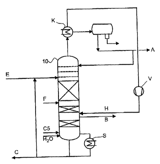
Figure 4 is a schematically shows a plant for carrying out the embodiment
without
a dividing wall, in which a middle boiler stream is supplied:
A single column 10 is supplied in its upper region with the selective solvent
E,
with the C4 fraction F in its middle region, and with a hydrogen stream H
below
the supply side of the stream F. A crude 1,3-butadiene stream B is taken off
as a
side stream. The column is equipped with trays in the region above the supply
side
of the stream E and below that point is equipped with random packing elements
or
ordered packings, some of which must be catalytically active. The vapor stream
is
condensed and taken off as a low boiler stream A, containing predominantly
butanes and butenes. From the column bottom, solvent is taken off into the
bottoms
vaporizer S, where it is partially purified and then recycled into the stream
E. A
middle boiler stream C5 is supplied at the bottoms vaporizer S.
Figure 5 schematically shows a plant for implementing the preferred process
variant where a stream of water is supplied, preferably in vapor form (H20-
vap) in
CA 02408325 2002-11-07
PF 0000051382-Wa
-15-
its lower region. This quantity of water is passed back into the column in a
circuit
by condensing the crude 1,3-butadiene stream and separating off the aqueous
phase
in a phase separator, preferably by evaporating it.
In the alternative illustrated in figure 6, which relates to a process where
an
increased 1,3-butadiene content is allowed in the bottoms liquid, the bottoms
liquid
is subjected to extractive stripping in a divided stripping column KS. For
this
purpose it is possible, as illustrated by way of example, to use the vapor
stream
from column 10.
Figure 7 schematically shows a further plant for implementing a process
variant
with an increased concentration of 1,3-butadiene. In this variant, the
stripping
column KS is placed against the column 10, as an additional bottommost section
Z,
and is separated from said column 10 in a gastight and fluidtight manner.
Examples:
A column with a total of 70 theoretical plates, with a column-top pressure of
4.5 bar, was supplied at the 45th tray, counting from the bottom, with a
volume
flow of 1.5 kg/h of a C4 fraction whose composition was as indicated earlier
on
above. At tray 65 an aqueous solution containing NMP, with a strength of 8.3%
by
weight, was supplied as the selective solvent. A hydrogen stream of 15 g/h was
supplied at tray 11. A crude 1,3-butadiene stream was taken off from tray 10.
In
the column bottom, a temperature of 186 C became established.
Under the experimental conditions indicated above, the volume flows of the
middle boiler 2-methylbutene supplied to the column bottom in each case were
as
set out below.
CA 02408325 2002-11-07
PF 0000051382-Wa
-16-
The reduction in bottoms-liquid temperature achieved in each case can be seen
from the table below:
Example No. C5 volume flow Temperature of bottoms
liquid ( C
1 3 184.6
2 6 183.4
3 30 175.2
4 60 168.1
120 159.2
6 240 150.2
5 Example 7:
Under the same experimental conditions as described initially, a steam stream
of
300 kg/h was supplied to the lower region of the column instead of a C5
stream.
This resulted in a reduction in bottoms-liquid temperature from 186 to 180 C.
Example 8:
The procedure of example 7 was repeated but with a higher volume of steam,
2 010 g/h, being supplied. This lowered the temperature in the bottoms liquid
to
165 C.