Note: Descriptions are shown in the official language in which they were submitted.
CA 02408330 2006-09-11
1
Headbox for a paper machine, board machine,
pulp machine or equivalent
The present invention relates to paper machines, board machines, pulp machines
or
equivalent. More specifically, the present invention relates to a headbox
which is
suitable for high basis weights and high fibre suspension consistencies.
This kind of conventional headbox of a paper machine or board machine or pulp
machine or equivalent is thus, for example, of the kind comprising a
turbulence part
for producing a turbulent fibre suspension flow, into which turbulence part a
fibre
suspension is coming from a distributor means of the fibre suspension,
advantageously a tube bank, and a slice part after the turbulence part, from
which
slice part the fibre suspension flows to a forming section of a fibrous web.
US Patent 4, 285, 767, Beloit Corp., discloses a headbox for a high
consistency fibre
suspension. The US patent proposes a flow passage, which is adjustable in its
cross-
sectional flow area and narrows stepwise towards a slice part, for a fibre
suspension
flowing in a foamed state in order that it might be assured that the fibres
are uniformly
distributed in the fibre suspension. The fibre suspension is passed into the
stepped
passage from a distributor means of the fibre suspension through tube
passages;
according to the US patent, the cross-sectional flow area is adjusted by
moving a
spindle part of the headbox axially away from and towards a slice part in
order to
increase and, correspondingly, to decrease the cross-sectional flow area.
The use of high consistency and the suitability of today's headboxes for use
as high
consistency headboxes involve a risk of cavitation and the fact that the use
of high
consistency requires fluidization of the fibre suspension in order that the
CA 02408330 2006-09-11
2
fibres might be caused to be distributed uniformly in the fibre suspension and
that the
quality of the web might be made satisfactory. On the other hand, increase of
fluidization limits increase of basis weight, for example, in pulp-drying
machines and
board machines.
The present invention is directed towards eliminating or at least reducing the
above-
noted problems associated with the use of high consistency and to provide an
improved headbox which is suitable for high fibre suspension consistencies
which are
in a range of 2-5 %. The device according to the invention is particularly
suitable for
high basis weights of over 400 g/m2, which are used in pulp-drying machines.
In accordance with one aspect of the present invention, there is provided a
headbox
for a paper machine, board machine, or pulp machine, which headbox is possible
for
high fibre suspension consistencies which are in a range to 2 to 5%, and which
headbox includes a turbulence part for producing a turbulent fibre suspension
flow,
into which turbulence part a fibre suspension flows from a fibre suspension
distributor
means, wherein the fiber suspension distributor means comprises a tube bank,
and
further comprising an explosion chamber before the turbulence part which
receives
the fibre suspension from the distributor means and which equalizes the
transverse
flow profile of the fibre suspension flow, and a slice part which is situated
after the
turbulence part and from which the fibre suspension flows to a forming section
of a
fibrous web, wherein the turbulence part comprises at least two passages,
which
converge in the flow direction of the fibre suspension towards the slice part
of the
headbox, in which connection the fibre suspension flow in the passages is
first
fluidized in a tortuous turbulence passage part and, after that, it
decelerates in a
widening deceleration passage part.
In accordance with a further aspect of the present invention, there is
provided a
headbox for a paper machine, board machine, or pulp machine, suitable for high
fibre
suspension consistencies which are in a range of 2 to 5%, the headbox
comprising: a
fibre suspension distributor, wherein the fiber suspension distributor
comprises a tube
bank; a turbulence part for producing a turbulent fibre suspension flow, into
which a
fibre suspension flows from the fiber suspension distributor; a slice part
which is
situated after the turbulence part and from which fibre suspension flows to a
fonning
CA 02408330 2006-09-11
2a
section of a fibrous web; and wherein the turbulence part comprises at least
two
passages, which converge in the flow direction of the fibre suspension towards
the
slice part, and each of the two passages has a tortuous turbulence passage
part
followed by a widening deceleration passage part, wherein each of the at least
two
passages has an explosion chamber positioned between said passage and the
distributor, the explosion chambers equalizing the transverse flow profile of
the fibre
suspension flow.
In accordance with an additional aspect of the present invention, there is
provided an
assembly of a headbox for a paper machine, board machine, or pulp machine and
a
high fibre suspension, the assembly comprising: a high fibre suspension having
fiber
consistencies in a range of 2 to 5% flowing through the headbox; a fibre
suspension
distributor comprised of a tube bank; a turbulence part for producing a
turbulent fibre
suspension flow, into which the fibre suspension flows from the fiber
suspension
distributor, the turbulence part being comprised of at least two passages
which
converge in the flow direction of the fibre suspension towards a slice part,
wherein
each of the two passages has a tortuous turbulence passage part followed by a
widening deceleration passage part, the slice part being situated after the
turbulence
part and from which the fibre suspension flows to a forming section of a
fibrous web,
wherein each of the at least two passages has an explosion chamber positioned
between said passage and the distributor, the explosion chambers equalizing
the
transverse flow profile suspension flow.
The invention is thus based on the novel and inventive basic idea that a fibre
suspension is discharged from distribution equipment of the fibre suspension
into an
explosion chamber that equalizes the transverse flow profile. After that, the
fibre
suspension flow passes into a turbulence part which comprises a double passage
construction for the fibre suspension flow, the passages of which constntction
converge in the flow direction towards each other and in which construction
the fibre
suspension flow is first fluidized in first tortuous turbulence passages and
then it
slows down, advantageously close to running speed, in second widening
deceleration
passages. Finally, the fibre suspension flows are combined in a slice part
after the
turbulence part, in which connection it is advantageous that the water
boundary layer
situated on the surface of the turbulence part is broken.
CA 02408330 2006-09-11
2b
In accordance with an advantageous embodiment of the invention, in the
turbulence
part, the angle of widening of an individual deceleration passage of the fibre
suspension flow has been selected such that the suspension cannot become
CA 02408330 2002-11-07
WO 01/86062 PCT/F101/00421
3
separated from the wall. In that connection, the angle is in a range of 0.5 -
7 ,
advantageously in a range of 2 - 3 , in which connection the risk of
cavitation is
minimized.
In accordance with the invention, it is additionally advantageous that the end
of
the spindle part defining the turbulence and deceleration passages on the
inside is
blunt and that the angle between the wall surfaces of the deceleration
passages for
the fibre suspension flows converging towards the end of the spindle part is
about
8- 16 .
It is also advantageous to the invention that the height of the slice part is
selected
such that the flow rate of the suspension flow slowed down in the deceleration
passage is maintained in the slice part in order to eliminate flocculation. In
that
connection, it is particularly advantageous, when the turbulence part has a
double
passage structure, that the cross-sectional flow area in the slice part is
twice the
cross-sectional flow area of a single deceleration passage, preferably at the
outlet
end of the deceleration passage. When the turbulence part has a triple passage
construction, for maintaining the flow rate of the suspension flow and for
preventing flocculation it is advantageous that the cross-sectional flow area
in the
slice part is three times the cross-sectional flow area of a single
deceleration
passage, preferably at the outlet end of the deceleration passage.
In the headbox according to the invention is it also possible to use methods
of
regulating the basis weight profile which are known in themselves and in which
the basis weight profile is regulated by means of dilution water. Such a
regulation
method is described in US Patefat No. 5,814,191. In addition, it is possible
to
adjust the height of the slice opening across the width of the headbox, by
means of
which the basis weight profile and/or fibre orientation is/are regulated. Both
regulation methods can also be used simultaneously.
CA 02408330 2002-11-07
WO 01/86062 PCT/F101/00421
4
With regard to the advantages of the invention, it may be mentioned that, for
example, in pulp machines, investment savings are of the order of 3.5 - 5.9
million euros with the current cost structure and, because of smaller flow
volumes
in the short circulation and in the wire section, annual pumping savings can
be
achieved which are of the order of 0.15 - 0.35 million euros with the current
cost
structure. A further advantage is that the capacity of old machines can be
increased in connection with rebuilding.
In the following, the invention will be described in greater detail with
reference to
the appended patent drawing, which is a longitudinal sectional view of an
embodiment of the invention regarded as advantageous.
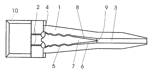
Figure 1 is a vertical longitudinal sectional view of a headbox according to
the
invention in the flow direction of a fibre suspension, i.e. in the machine
direction.
The headbox according to the invention includes a turbulence part 1 which has
a
double passage structure and into which a fibre suspension flows from a fibre
suspension distributor means 2, which is advantageously a tube bank, and a
slice
part 3. The fibre suspension flows passing as separate flows from each other
in the
turbulence part 1 are combined in the slice part 3, after which the combined
fibre
suspension flow passes to a forming section of a fibrous web (not shown in the
figure). Moreover, the headbox comprises an inlet header 10, by means of which
the fibre suspension flow is distributed evenly across the entire width of the
headbox.
In accordance with the invention, the headbox which is intended for high basis
weights of over 400 g/m2 and for high fibre suspension consistencies in a
range of
2 - 5 % comprises an explosion chamber 4 for receiving the fibre suspension
from
the tube bank 2, which explosion chamber equalizes the transverse flow profile
of
the fibre suspension flow.
CA 02408330 2002-11-07
WO 01/86062 PCT/F101/00421
In addition, in accordance with the invention, the turbulence part 1 after the
explosion chamber has a structure comprising at least two passages,
advantageously a double or triple passage structure, the passages 5, 6 of
which
converge towards each other in the flow direction of the fibre suspension, in
5 which connection the fibre suspension flow in each passage is first
fluidized in a
first passage part, which is a tortuous turbulence passage part 5, and after
that it
decelerates, advantageously close to running speed, in a second passage part,
which is a deceleration passage part 6, which continuously widens up to the
slice
part 3. In that connection, it is advantageous that, in the turbulence part 1,
the
angle of widening of an individual deceleration passage 6 is in a range of 0.5
- 7 ,
advantageously in a range of 2 - 3 . Too small or too large an angle of
widening
leads to insufficient or excessive deceleration, respectively, in which case
too
great a difference between the running or production speed of the machine and
the
flow rate of the fibre suspension to the web forming section becomes a
problein.
In accordance with an advantageous embodiment of the invention, an explosion
chamber 4 has been arranged at the initial end of both passages of the
turbulence
part 1 having a double passage construction. Alternatively, the explosion
chambers 4 can be arranged so as to form an extension of the tube bank 2, in
which connection the fibre suspension flows into both passages 5, 6 of the
turbulence part I from the explosion chambers preceding the passages.
As shown in the figure, both passages 5, 6 of the turbulence part 1 of the
headbox
according to the invention are defined by a central spindle part 7 and the
fibre
suspension flows are combined in the slice part 3 situated after the
turbulence part
1 such that the water boundary layer on the surface of the spindle part 7 of
the
turbulence part 1 is broken. In that connection, it is advantageous in
accordance
with the invention that the end 8 of the spindle part 7 defining the
turbulence
and/or deceleration passages 5, 6 on the inside is blunt, and that the walls 9
of the
spindle part 7 defining the widening deceleration passages 6 converge towards
the
blunt end 8 of the spindle part. In accordance with the invention, an
advantageous
CA 02408330 2002-11-07
WO 01/86062 PCT/F101/00421
6
angle between the converging walls 9 is in a range of 8 - 16 , for example,
about
11-12 .
In the headbox according to a preferred embodiment of the invention, the
height
of the slice part 3 has been selected such that the flow rate of the
suspension flow
decelerated in the deceleration passage 6 is maintained in the slice part 3,
whereby
the risk of flocculation can be eliminated. In addition, the length of the
slice part 3
has been selected such that the suspension flows coming from the deceleration
passage 6 have time to be mixed before discharge to the web forming section.
Further, it is advantageous that the cross-sectional flow area in the slice
part 3 is,
in relation to the cross-sectional flow area of a single deceleration passage
6, in
particular at the outlet side end of the deceleration passage 6,
- double when the turbulence part I comprises two passages,
- treble when the turbulence part comprises three passages (not shown in the
figure),
- quadruple when the turbulence part comprises four passages (not shown in
the figure), i.e. the cross-sectional flow area of the deceleration passage 6
corresponds to a multiple of the cross-sectional flow area of a single
deceleration passage 6 depending on the passage construction of the
turbulence part 1.
Above, the invention has been described only by way of example by means of one
of its einbodiments regarded as advantageous. Of course, this is not intended
to
limit the invention and, as is clear to a person skilled in the art, the
invention can
be varied and modified within the scope of protection of the inventive idea
defined in the appended claims.