Note: Descriptions are shown in the official language in which they were submitted.
CA 02408524 2002-11-08
WO 01/87215 PCT/USO1/15713
ABSORBENT STRUCTURE WITH INTEGRAL VAPOR
TRANSMISSIVE MOISTURE BARRIER
RELATED APPLICATION DATA
This application claims priority under 35 U.S.C. 119 from U.S. provisional
application serial numbers 60/204,418, filed May 12, 2000 and 60/252,544,
filed
November 22, 2000, both of which are hereby incorporated by reference in their
entirety.
FIELD OF THE INVENTION
The present invention relates to absorbent structures useful in
absorbent products such as disposable diapers, feminine hygiene products such
as
sanitary napkins and pantiliners, absorbent surgical pads, adult incontinence
products,
and other personal hygiene articles. More particularly, the present invention
is
directed to an absorbent structure including an absorbent core for absorbing
and
retaining fluids and a vapor-transmissive, moisture barrier integral
therewith.
BACKGROUND OF THE INVENTION
Feminine hygiene products, such as sanitary napkins, pantiliners, and
other personal hygiene articles, are typically constructed with a body side
liquid
pervious topsheet, a liquid impervious backsheet and an absorbent structure,
or core,
sandwiched between the two. The construction of a typical product is such that
the
topsheet and backsheet are in intimate contact with the absorbent core and
stabilized
with an adhesive to keep them in intimate contact.
The backsheet is positioned on the garment-facing side of the product.
The backsheet is necessary to provide a fluid barrier between the absorbent
core and
the user, preventing body exudates, imbibed by the absorbent core, from
soiling the
skin or clothing of the user.
CA 02408524 2002-11-08
WO 01/87215 PCT/USO1/15713
2
The backsheet is typically impermeable to moisture vapor, that is, it
has little or no vapor transmission properties. Thus, any vapors generated in
use, such
as perspiration or vaporization of volatiles by body heat, cannot escape and
can cause
skin wetness and discomfort while the product is being used.
There has been a trend in the state of the art to design "breathability"
into absorbent products to improve skin health and comfort of the user. In
such
products, the liquid impervious backsheet is replaced with a microporous
material that
has vapor transmission properties. The backsheet barrier is interrupted with
small
pores to allow vapors to escape; thus, the backsheet is not continuous.
However, there
is also an opportunity for the fluid to strike through the backsheet material,
particularly upon the application of pressure commonly encountered during
normal
use of the absorbent product, resulting in wetting of the skin or clothing of
the user.
Accordingly, the use of a breathable, microporous backsheet in an
absorbent product requires that additional steps be taken to protect the user
from
exposure to the body exudates imbibed by the absorbent core. One option is to
overdesign the absorbent core such that it has sufficient absorbent capacity
to hold the
fluid and prevent it from exiting the core and striking through the backsheet.
This
results in thicker, less comfortable products and adds undesirable cost to the
absorbent
core.
Alternatively, an additional barrier material may be positioned between
the absorbent core and the microporous backsheet. The additional barrier
material
may be a synthetic nonwoven or an apertured film. The material serves to
provide
additional barrier properties but also provides a space or gap between the
absorbent
core and the backsheet reducing the possibility that the fluid will strike
through the
core. The requirement for two separate layers adds expense and additional
manufacturing steps to the structure.
Illustrative examples of absorbent products incorporating breathable
backsheets are found in U.S. Patents 3,932,682 to Loft et al., 3,989,867 to
Sisson,
4,196,245 to Kitson et al., 4,306,559 to Nishizawa et a1.,4,341,216 to
Obenour,
4,609,584 to Cutler et al., 4,626,252 to Nishizawa et al., 4,681,793 to Linman
et al.,
4,713,068 to Wang et al., 4,713,069 to Wang et al., 4,758,239 to Yeo et al.,
4,818,600
CA 02408524 2002-11-08
WO 01/87215 PCT/USO1/15713
3
to Braun et al., 4,828,556 to Braun et al., 5,364,381 to Soga et al.,
5,498,463 to
McDowall et al., 5,560,974 to Langley and 5,843,056 to Good et al., all of
which are
hereby incorporated by reference.
Illustrative examples of absorbent products incorporating foams in
absorbent products are found in U.S. Patents 4,554,297 to Dabi, 4,740,528 to
Garvey
et al., 5,260,345 to DesMarais et al., 6,040,494 to Kalentun et al. and
6,107,356 to
DesMarais, WO 99/61518 to Chen et al. and WO 00/13637 to Carlucci et al, all
of
which are hereby incorporated by reference.
The disclosure WO 00/13637 describes an absorbent article containing
a single foam layer, characterized by an absorbent-core portion of the foam
treated to
be hydrophilic and a backsheet portion treated to be hydrophobic.
SUMMARY OF THE INVENTION
It would be desirable to provide an absorbent core for use in an
absorbent product having an integral vapor-transmissive moisture barrier. Such
a core
would be less expensive and easier to manufacture than prior art arrangements
involving separately formed materials which must be combined and adhered
together
to form a product
It is one object of the present invention to provide a unitary absorbent
core, including a fibrous absorbent layer and a vapor-transmissive moisture
barrier
integral with one surface of the absorbent layer, which is thinner and more
comfortable in use in disposable absorbent products, such as feminine hygiene
products, diapers and adult incontinence products.
It is another object of the present invention to provide a unitary
absorbent core including an integral vapor-transmissive moisture barrier which
is less
expensive to manufacture compared to absorbent cores incorporating apertured
films,
synthetic nonwovens and adhesives.
It is yet another object of the present invention to provide a unitary
absorbent core including an integral vapor-transmissive moisture barrier which
allows
for simple conversion into a finished absorbent product, based on a reduction
in the
number of raw materials and process steps required to carry out the
conversion.
CA 02408524 2002-11-08
WO 01/87215 PCT/USO1/15713
4
It is another object of the present invention to provide a unitary
absorbent core including an integral vapor-transmissive moisture barrier that
is highly
breathable, but also maintains a significant moisture barrier.
Another object of the present invention is to provide a unitary
absorbent core including an integral vapor-transmissive moisture barrier and
which
also provides softness, drape and hand comparable to or better than that
provided by a
unitary absorbent core having an apertured film moisture barrier.
These and other objects are met by the present invention which is
directed to a unitary absorbent core having a basis weight of about 75 gsm or
greater
comprising a fibrous absorbent layer having an upper fluid receiving surface
and a
lower surface with a hydrophobic vapor-transmissive moisture barrier integral
with
the lower surface of the absorbent layer. In a preferred embodiment, the
barrier may
be a hydrophobic latex emulsion applied to one surface of the absorbent layer.
The
absorbent core exhibits both a high water vapor transmission rate and a
significant
hydrostatic head (hydrohead) pressure. The absorbent core may have a moisture
barrier which has a structure which substantially includes fibers coated with
hydrophobic material, or it may have a moisture barrier which has a
reticulated
remnant of a barrier material emulsion extending from the lower surface region
of the
absorbent layer to form an outer reticulated foam barrier. A reticulated foam
barrier is
a very open structure, more open than the open celled structures known in the
foam
making art. Barriers of this type generally present a greater challenge to
fluids trying
to pass than barriers where the structure substantially includes fibers coated
with
hydrophobic material.
Within the scope of this invention is a process for the production of a
unitary absorbent core having a basis weight of about 75 gsm or greater
comprising a
fibrous absorbent layer having an upper fluid receiving surface and a lower
surface
with a hydrophobic vapor-transmissive moisture barrier integral with the lower
surface of the absorbent layer comprising:
(a) producing a fibrous absorbent layer having upper and lower
surfaces,
CA 02408524 2002-11-08
WO 01/87215 PCT/USO1/15713
(b) applying to the lower surface of the fibrous absorbent layer a
hydrophobic material which at least partially coats the fibers of the lower
surface of
the absorbent layer. Desirably, the hydrophobic material is an emulsion
polymer,
which is applied in the form of a foam to a fibrous absorbent layer comprising
synthetic and/or natural fibers in a nonwoven produced by an airlaid process.
This
aspect of this invention includes a unitary absorbent core produced by the
process.
Further, this invention provides an absorbent article comprising:
(A) a liquid pervious top sheet, and
(B) a unitary absorbent core of this invention, which may also have
(C) a microporous backsheet.
The article may be in the form of an infant disposable diaper, a training
pant, an absorbent surgical pad, an adult incontinence device, a sanitary
napkin, a
pantiliner or a feminine hygiene pad.
In a further aspect, this invention is a breathable nonwoven fibrous
material having a basis weight of about 75 gsm or greater, a barrier
effectiveness
value of 30 mm or greater, and having a surface with a hydrophobic vapor-
transmissive moisture barrier integral therewith comprising natural fibers,
synthetic
fibers or a mixture thereof, and a hydrophobic material which at least
partially coats
the fibers of a surface of the material.
In a further aspect, this invention includes a breathable, partially
fibrous or nonfibrous nonwoven material or structure having a basis weight of
about
45 gsm or greater, a barrier effectiveness value of 30 mm or greater, and
having a
surface with a hydrophobic vapor-transmissive moisture barrier integral
therewith, the
material or structure including one or more spunbonded, meltblown, coformed,
bonded carded, or foamed constituents, optionally in combination with natural
fibers,
synthetic fibers or a mixture thereof.
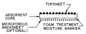
BRIEF DESCRIPTION OF THE FIGURES
Figure 1 is a schematic representation of a conventional absorbent
product having a topsheet and a non-permeable backsheet.
Figure 1 a is a schematic representation of a pore.
CA 02408524 2002-11-08
WO 01/87215 PCT/USO1/15713
~6
Figure 2 is a schematic representation of a conventional absorbent
product having a topsheet and a microporous backsheet with an apertured film
layer.
Figure 3 is a schematic representation of one embodiment of the
present invention, including an optional microporous backsheet.
Figure 4 is a photomicrograph generated by scanning electron
microscopy (SEM) at a magnification of 80X of an untreated lower surface of an
absorbent layer of a unitary absorbent core.
Figure 5 is a photomicrograph generated by scanning electron
microscopy (SEM) at a magnification of 80X of an treated lower surface of an
absorbent layer of a unitary absorbent core.
Figure 6 is a photomicrograph generated by scanning electron
microscopy (SEM) at a magnification of 350X of an untreated lower surface of
an
absorbent layer of a unitary absorbent core.
Figure 7 is a photomicrograph generated by scanning electron
microscopy (SEM) at a magnification of 350X of an treated lower surface of an
absorbent layer of a unitary absorbent core.
Figures 8A and 8B are photomicrographs generated by scanning
electron microscopy (SEM) at magnifications of 45X and 80X of an untreated
lower
surface of an absorbent layer of a unitary absorbent core.
Figures 9A and 9B are photomicrographs generated by scanning
electron microscopy (SEM) at magnifications of 250X and 450X of an untreated
lower surface of an absorbent layer of a unitary absorbent core.
Figures 10A and l OB are photomicrographs generated by scanning
electron microscopy (SEM) at magnifications of 45X and 80X of a treated lower
surface of an absorbent layer of a unitary absorbent core with reticulated
remnant of
the barrier material emulsion.
Figures 1 1A and 11B are photomicrographs generated by scanning
electron microscopy (SEM) at magnifications of 250X and 450X of a treated
lower
surface of an absorbent layer of a unitary absorbent core with reticulated
remnant of
the barrier material emulsion.
CA 02408524 2002-11-08
WO 01/87215 PCT/USO1/15713
7
Figures 12(a) and 12(b) are photomicrographs at a magnifications of
7.5X and 40X, respectively of the unitary absorbent core of Example 25.
Figures 13(a) and 13(b) are photomicrographs generated by scanning
electron microscopy (SEM) at magnifications of 35X and 100X, respectively, of
the
surface of the unitary absorbent core of Example 25.
Figures 14(a) and 14(b) are photomicrographs generated by scanning
electron microscopy (SEM) at magnifications of 35X and 100X, respectively, of
the
cross-section of the unitary absorbent core of Example 25.
DETAILED DESCRIPTION OF THE INVENTION
All U.S. patents cited herein are hereby incorporated by reference. In
the case of a conflict in terminology, the present disclosure controls.
The unitary absorbent core of the present invention includes a fibrous,
absorbent layer having an upper fluid receiving surface and a lower surface,
and a
vapor-transmissive moisture barrier integral with the lower surface of the
absorbent
layer.
The fibrous absorbent core may be formed using materials and
techniques well known in the art. For example, the core may include one or
more .
layers or strata of natural or synthetic fibers, hereinafter referred to as an
"absorbent
layer." Cellulosic fibers are preferred for use in the absorbent layer. The
absorbent
layer may be formed using wetlaid or airlaid techniques, although airlaid
processes
are preferred. Binders, such as, for example, wet strength agents, latex
emulsions,
thermoplastic bicomponent fibers ("bico") and combinations thereof, may be
incorporated into the absorbent layer. The term "multibonded" is used to
describe an
absorbent layer incorporating a combination of binders including a preferred
combination of latex and bico. Small amounts of a water-based hydrophilic
emulsion
binder may be applied to the surfaces of the absorbent layer to reduce "dust-
off' of
loose fibers and other particles. Further, for improved absorption of fluids,
superabsorbent polymers (SAP) may be incorporated into the absorbent layer.
SAP
may be incorporated into the absorbent layer as particles, granules, flakes,
etc., and
may be included as a discrete stratum or mixed with the fibers of the
absorbent layer.
CA 02408524 2002-11-08
WO 01/87215 PCT/USO1/15713
8
Materials such as fillers, perfumes, surfactants, and additives may be
included in the
core. Desirable absorbent cores suitable for use in the practice of this
invention and
components suitable for use in the cores are described in WO 99/16961, WO
99/63922, WO 99/63923, WO 99/63925, WO 00/41882, WO 00/38607, all of which
are hereby incorporated by reference.
In a preferred embodiment, the unitary absorbent core of this invention
can be described as a multi-zone or multi-strata or multilayer absorbent
structure,
which has two or more distinct strata. As used herein, the terms "stratum" and
"strata" refer to the layered regions which make up the unitary structure. The
unitary
structure is constructed by assembling the strata in a continuous manner in a
series of
unit operations which results in the production of the unitary absorbent core.
The
strata of the unitary structure is not an assembly or laminate of preformed
layers or
plies which are assembled on a converting line. Notwithstanding the previous
statement, in an optional variation of a preferred embodiment related to the
continuous airlaid process of this invention, a carrier tissue of low basis
weight or a
separate stratum may be used to facilitate the production of a fibrous
absorbent Iayer
having a plurality of strata. In one embodiment, a preferred unitary absorbent
core of
this invention has two or more strata, at least one of which is a fibrous
absorbent layer
having an upper fluid receiving surface and a lower surface, and a vapor-
transmissive
moisture barrier integral with the lower surface of the absorbent layer. In a
preferred
embodiment, the unitary absorbent core is produced in a continuous manner
using
airlaid technology, where an individual forming head provides material for a
single
stratum and constitutes one unit operation in the series. Other unit
operations in the
series include application of a froth or foam which produces the vapor-
transmissive
moisture barrier, and may include compression and calendering and drying
operations.
The moisture barrier may be applied at any stage of the manufacture of the
unitary
absorbent core, e.g. after all the strata have been formed, or after any one
or more
strata have been formed.
Generally herein, the term "froth" is used to describe foam that is of
low viscosity and of poor stability, which is easily collapsible after
application to the
lower surface of the fibrous absorbent layer to form a hydrophobic vapor-
transmissive
CA 02408524 2002-11-08
WO 01/87215 PCT/USO1/15713
9
moisture barrier integral with the lower surface of the absorbent layer
wherein the
moisture barrier has a structure which substantially includes fibers coated
with
hydrophobic material. The terms "stand-up foam" and "stand-up foam barrier"
are
used to describe a more substantial foam, which, after application to the
lower surface
of a fibrous absorbent layer to form a hydrophobic vapor-transmissive moisture
barrier integral with the lower surface of the absorbent layer, results in
some coating
of fibers, but also wherein the moisture barrier has a reticulated remnant of
a barrier
material emulsion extending from the lower surface region of the absorbent
layer to
form an outer reticulated foam barrier. Moisture barriers with reticulated
remnants of
barrier material emulsions are shown in Figs. 10 and 11.
The unitary absorbent core of this invention has a basis weight of about
75 gsm (grams per square meter) or greater, generally from about 80 to about
1000
gsm, and preferably from about 100 gsm to about 500 gsm, and more preferably
from
about 125 gsm to about 350 gsm.
In another embodiment, a breathable, partially fibrous or nonfibrous
nonwoven material or structure including one or more spunbonded, meltblown,
conformed, bonded carded, or foamed constituents has a basis weight of about
45 gsm
or gretaer.
The unitary absorbent core of this invention has a density of from
about 0.03 g/cc to about 0.7 g/cc, preferably from about 0.04 g/cc to about
0.3 g/cc.
The structures of this invention can include natural fibers, synthetic
fibers or mixtures of both natural and synthetic fibers. Examples of the types
of
natural fibers which can be used in the present invention include fluffed
cellulose
fibers prepared from cotton, softwood and/or hardwood pulps, straw, keaf
fibers,
cellulose fibers modified by chemical, mechanical and/or thermal treatments,
keratin
fibers such as fibers obtained from feathers, bagasse, hemp, and flax, as well
as man-
made staple fibers made with natural polymers such as cellulose, chitin, and
keratin.
Cellulosic fibers include chemically modified cellulose such as chemically
stiffened
cellulosic fibers by crosslinking agents, fibers treated with mercerizing
agents and
cellulose acetate. Examples of suitable synthetic matrix fibers include
polyethylene,
polypropylene, polyester, including polyester terephthalate (PET), polyamide,
CA 02408524 2002-11-08
WO 01/87215 PCT/USO1/15713
polyacetates, cellulose acetate and rayon fibers. Certain hydrophobic
synthetic fibers,
such as polyolefins, may be surface treated with surfactant to improve
wettability, or
may be used untreated, depending upon their intended function within the core.
Examples of binders which may be useful in the absorbent structure of
5 the present invention include polymeric binders in a solid or liquid form.
The term
"polymeric binder" refers to any compound capable of creating interfiber bonds
between matrix fibers to increase the integrity of the stratum. At the same
time, the
binder may optionally bind fibers and SAP particles to each other.
For example, a dispersion of natural or synthetic elastomeric latex may
10 be used as a binder. Thermoplastic fibers or powder, which are well known
in the art,
are also commonly used to provide bonding upon heating of the absorbent
structure to
the melting point of the thermoplastic fiber or powder. Other binders, which
can be
used for stabilizing the absorbent structure of the present invention, include
bonding
agents used to bond cellulose fibers. These agents include polymers dispersed
in
water, which are cured after application to the fibrous web and create bonds
between
fibers or between fibers and SAP particles. Examples of such agents include
various
cationic starch derivatives and synthetic cationic polymers containing
crosslinkable
functional groups such as polyamide-polyamine epichlorohydrin adducts,
cationic
starch, dialdehyde starch and the like. Any combination of the above-described
polymeric binders may be used for stabilizing the structure of the present
invention.
Binders useful in the structures of the invention include binders in
liquid form or having a liquid carrier, including latex binders. Useful latex
binders
include vinyl acetate and acrylic ester copolymers, ethylene vinyl acetate
copolymers,
styrene butadiene carboxylate copolymers, and polyacrylonitriles, and sold,
for
example, under the trade names of Airbond, Airflex and Vinac of Air Products,
Inc.,
Hycar and Geon of Goodrich Chemical Co., and Fulatex of H. B. Fuller Company.
Alternatively, the binder may be a non-latex binder, such as epichlorohydrin
and the
like.
For bonding the fibers specifically, and for structural integrity of the
unitary absorbent core generally, water-based latex binders may be used.
Alternatively, or in combination with a latex binder, thermoplastic binding
material
CA 02408524 2002-11-08
WO 01/87215 PCT/USO1/15713
11
(fibers or powders) may be used for bonding upon heating to the melting point
of the
thermoplastic binding material. Suitable thermoplastic binding material
includes
thermoplastic fibers, such as bicomponent thermoplastic fibers ("bico").
Preferred
thermoplastic binding fibers provide enhanced adhesion for a wide range of
materials,
including synthetic and natural fibers, particles, and synthetic and natural
carrier
sheets. An exemplary thermoplastic bico fiber is Celbond Type 255 Bico fiber
from
KoSa.
Other suitable thermoplastic fibers include polypropylenes, polyesters,
nylons and other olefins, or modifications thereof. A preferred thermoplastic
fiber is
FiberVisions type AL-Adhesion-C Bicomponent Fiber, which contains a
polypropylene core and an activated copolyolefin sheath. In certain
embodiments, the
binder in the invention is a binding fiber, which is present in the absorbent
structure in
an amount which is less than about 10 percent by weight of the weight of SAP
particles. In other embodiments of the invention, the binder fibers are
present in an
amount which is less than about 7 percent by weight of the weight of the
absorbent
structure.
Functional particles for use in the absorbent cores of the invention
include particles, flakes, powders, granules or the like which serve as
absorbents, odor
control agents, such as, for example, zeolites or calcium carbonates,
fragrances,
detergents, antimicrobial agents and the like. The particles may include any
functional powder or other particle having a particle diameter up to 3,OOOg
(microns).
In some preferred embodiments, the functional particles used in the core
include super
absorbent polymer particles ("SAP"). In one desirable embodiment of this
invention,
the unitary absorbent core contains from about 5 to about 90 percent by weight
of
SAP, preferably from about 10 to about 80 percent by weight of SAP, more
preferably
from about 10 to about 50 percent by weight of SAP.
U.S. PatentNos. 5,147,343; 5,378,528; 5,795,439; 5,807,916; and
5,849,211, which describe various superabsorbent polymers and methods of
manufacture, are hereby incorporated by reference. Examples of the types of
SAP
particles which may be used in this invention, include superabsorbent polymers
in
their particulate form such as irregular granules, spherical particles, staple
fibers and
CA 02408524 2002-11-08
WO 01/87215 PCT/USO1/15713
12
other elongated particles. The term "superabsorbent polymer" or "SAP" refers
to a
normally water-soluble polymer, which has been cross-linked. There are known
methods of making water-soluble polymers such as carboxylic polyelectrolytes
to
create hydrogel-forming materials, now commonly referred to as superabsorbents
or
SAPS, and it is well known to use such materials to enhance the absorbency of
disposable absorbent articles. There are also known methods of crosslinking
carboxylated polyelectrolytes to obtain superabsorbent polymers. SAP particles
useful in the practice of this invention are commercially available from a
number of
manufacturers, including Dow Chemical (Midland, Michigan), Stockhausen
(Greensboro, North Carolina), and Chemdal (Arlington Heights, Illinois). One
conventional granular superabsorbent polymer is based on poly(acrylic acid)
which
has been crosslinked during polymerization with any of a number of mufti-
functional
co-monomer crosslinking agents, as is well known in the art. Examples of
multifunctional crosslinking agents are set forth in U.S. Patent Nos.
2,929,154;
3,224,986; 3,332,909; and 4,076,673, all of which are hereby incorporated by
reference. Other water-soluble polyelectrolyte polymers are known to be useful
for
the preparation of superabsorbents by crosslinking, these polymers include
carboxymethyl starch, carboxymethyl cellulose, chitosan salts, gelatin salts,
etc. They
are not, however, commonly used on a commercial scale to enhance absorbency of
disposable absorbent articles, primarily due to lower absorbent efficiency or
higher
cost.
Superabsorbent particulate polymers are also described in detail in U.S.
Patents 4,102,340 and Re 32, 649, both of which are hereby incorporated by
reference. Suitable SAPS yield high gel volumes or high gel strength as
measured by
the shear modulus of the hydrogel. Such preferred SAPS contain relatively low
levels
of polymeric materials that can be extracted by contact with synthetic urine
(so-called
"extractables"). SAPs are well known and are commercially available from
several
sources. One example is a starch graft polyacrylate hydrogel marketed under
the
name IM1000 (Hoechst-Celanese; Portsmouth, VA). Other commercially available
SAPs are marketed under the trademark SANWET (Sanyo Kasei Kogyo; Kabushiki,
Japan), SUMIKA GEL (Sumitomo Kagaku Kabushiki; Haishi, Japan), FAVOR
CA 02408524 2002-11-08
WO 01/87215 PCT/USO1/15713
13
(Stockhausen; Garyville, LA) and the ASAP series (Chemdal; Aberdeen, MS). Most
preferred for use with the present invention are polyacrylate-based SAPs. As
used in
the present invention, SAP particles of any size or shape suitable for use in
an
absorbent core may be employed.
The vapor-transmissive moisture barrier integral with the lower surface
of the absorbent layer is formed by applying a hydrophobic material to a
fibrous
substrate for which it is desirable to impart a barrier to the transmission of
liquids, but
for which it is also desirable to permit the passage of vapors including water
vapor.
The hydrophobic moisture barrier comprises a hydrophobic material which at
least
partially coats the fibers of the lower surface of the absorbent layer. The
hydrophobic
material can be a natural or synthetic polymer, or a mixture thereof. Figures
4 and 6
show the lower surface of the absorbent layer of an airlaid nonwoven absorbent
core,
as prepared in Example A below, which is untreated. Figures 5 and 7 show the
treated
lower surface of the absorbent layer of an airlaid nonwoven absorbent core, as
prepared in Example B below. The term "vapor-transmissive moisture barrier
integral
with the lower surface of an absorbent layer" as used herein means that the
barrier
material at least partially coats at least some of the individual fibers of
the absorbent
layer, as shown in Figures 5 and 7, but that a continuous film is not formed.
The
absorbent layer remains vapor-transmissive since the pore structure between
the
untreated fibers, shown in Figures 4 and 6, remains substantially open after
treatment
to form the barrier, as shown in Figures 5 and 7. With the moisture barrier in
place on
the substrate, the unitary absorbent core has a hydrohead of 30 mm or greater
as
measured by modified EDANA nonwoven repellency test 120.1-80, a strikethrough
of
1.8 g or less as measured by the standard strikethrough test, an air
permeability of 18
m3lmin/m2 (60 ft3/min/ft2) or greater as measured by modified ASTM D 737-96,
and
a water vapor transmission rate (WVTR) of 500 g/m2/24 hr or greater. In one
embodiment, the unitary absorbent core has a hydrohead of 85 mm or greater, a
strikethrough of 0.08 or less, and an air porosity of 235 CFM or greater.
Within the scope of this invention is a vapor-transmissive moisture
barrier integral with the lower surface of an absorbent layer where the
hydrophobic
barrier material coats at least some of the individual fibers of the absorbent
layer, and
CA 02408524 2002-11-08
WO 01/87215 PCT/USO1/15713
14
where a reticulated remnant of a barrier material emulsion extends from the
surface
region of the absorbent layer to form an outer reticulated foam barrier as
shown in
Figures 10 and 11. In Figure 10, the SEM photomicrograph at 80X shows several
fibers intermingled with the reticulated remnant of the barrier material
emulsion.
Hydrophobic materials suitable for use in this invention include a wide
variety of materials known for water repellency, such as, for example, water
insoluble
thermoplastic organic materials including hydrocarbons and naturally occurring
resins
from petroleum, asphalt and coal tar, organic silicon compounds including
polyorganosiloxanes, polysiloxanes containing halogens, especially fluorine,
halohydrocarbons, especially polymers containing chlorine and fluorine, and
various
polymers in the form of natural or synthetic emulsions. Emulsion polymers
suitable
for use in this invention include lattices containing polymers, copolymers, as
well as
mixtures and blends of polymers and copolymers, containing in polymerized form
one
or more monomers of vinyl acetate, vinyl chloride, vinyl alcohol, acrylics,
acrylates,
acrylonitrile, ethylene, propylene, styrene, butadiene, isoprene, and various
halogenated counterparts thereof.
In a preferred embodiment, the vapor-transmissive moisture barrier is
formed by applying a hydrophobic polymeric latex emulsion to the lower surface
of
the absorbent layer. In at least one embodiment, it is desirable that a
barrier is
produced which has a contact angle for water on the film cast from an emulsion
of
about 80° or greater, as measured by he contact angle test (described
below).
Suitable hydrophobic polymeric emulsions include emulsions of both natural and
synthetic polymers, including synthetic latexes. Several manufacturers supply
such
latex emulsions including Rohm and Haas, B.F. Goodrich, Air Products Polymers
and
Unichem Inc. A preferred latex emulsion is Unibond 0930 (IJnichem Inc.,
Greenville,
SC) which is an acrylic polymer. The emulsion can be applied by a variety of
methods known in the art, including spray, brush, doctor blade, roller, and
foam.
Foam application is preferred.
The preferred application process involves the injection of air into an
emulsion to form bubbles and create a temporary foam, or froth. In this
application
process, the collapse of the froth and elimination of air bubbles during the
process of
CA 02408524 2002-11-08
WO 01/87215 PCT/USO1/15713
drying and curing the emulsion occurs. Advantages of foam application are more
uniform reagent distribution, ability to apply reagent at higher solids
contents, and
more control over reagent penetration into the substrate.
For the embodiment of this invention where the moisture barrier
5 produced has a reticulated remnant of a barrier material emulsion extending
from the
lower surface region of the absorbent layer to form an outer reticulated foam
barrier, it
is preferable to use a foam that has greater stability than the easily
collapsible foams
used for moisture barrier formation where no outer reticulated foam barrier is
produced.
10 For a description of suitable conventional foaming procedures and
foam stabilizers and foaming agents, reference is made to Mage, E. W., "Latex
Foam
Rubber," John Wiley and Sons, New York (1962) and Rogers, T. H , "Plastic
Foams",
Paper, Reg. Tech. Conf., Palisades Sect., Soc. Plastics Engrs., New York,
November,
1964. Most common are the alkali metal, ammonia, and amine soaps of saturated
or
15 unsaturated acids having, for example, from about 12 to about 22 carbon
atoms.
Ea~amples of suitable soaps include tallow soaps and coconut oil soaps,
preferably the
volatile amine or ammonia soaps, so that the volatile portion is vaporized
from the
foam. Other useful foaming-foam-stabilizing agents include lauryl sulfate-
lauryl
alcohol, lauryl sulfate-lauric acid, sodium lauryl sulfate, and other commonly
used
foamed stabilizers or foaming agents.
A preferred emulsion for the formation of the moisture barrier
produced with a reticulated remnant of a barrier material emulsion extending
from the
lower surface region of the absorbent layer to form an outer reticulated foam
barrier is
Unibond 0938 from Unichem, which is an acrylic copolymer dispersed in a water
base. Application by foam is preferred for Unibond 0938.
Unibond 0938 is engineered so that it does not collapse on the surface
upon which it is foamed. After the Unibond 0938 foam is dried and cured, an
elastic,
reticulated structure, a reticulated remnant of the barrier material emulsion
remains on
the surface. See Figures 8A-11B, which are scanning electron micrographs
(SEMs) of
treated and untreated surfaces.
CA 02408524 2002-11-08
WO 01/87215 PCT/USO1/15713
16
Generally, whether the moisture barrier formed has a reticulated
remnant of the barrier material emulsion is a consequence primarily of the
stability of
the foam, which is influenced by the nature of the emulsion polymer in the
emulsion,
whether a foam stabilizer is used and the process conditions during
application. In
practice this is easily controlled.
After application of the latex emulsion to the surface of the absorbent
layer, the emulsion is cured by removing water by drying or heat application.
Optionally, crosslinking agents or other curing agents may be employed. Other
additives may be included in the emulsion, such as biocides, water repellents,
fillers
and colorants.
Whichever application technique is used, it is important that the latex
emulsion be applied in a sufficient quantity to at least partially coat a
majority of
individual fibers in the surface region of the absorbent layer. As used
herein, "surface
region" refers to the fibers of the absorbent layer directly exposed to
the.surface and
several layers of fibers below such outermost fibers to a depth of from about
0.01 mm
to about 1.0 mm from the surface, and preferably from about 0.05 mrn to about
0.8
mm from the surface. As used herein, "partially coat" refers to the average
portion of
the surface area of a specific fiber coated with emulsion. Preferably, the
fibers are l
coated by at least enough emulsion to render the fibers hydrophobic.
At the same time, it is important that the amount of latex emulsion
applied not be so great that a continuous layer or film of polymer is formed
which
would block the pores. A continuous layer is disadvantageous because of the
adverse
affect on water vapor permeability of the resultant structure.
The amount of emulsion necessary to provide coated fibers without
forming a continuous film or layer depends upon the density of the absorbent
layer,
the type of fibers employed, the type and physical properties of the emulsion
employed, the method of application and the method of curing the absorbent
core.
Without wishing to be bound by theory, it is believed that application
of at least a partial coating of surface fibers with latex emulsion provides a
hydrophobic moisture barrier, but because a continuous film or layer is not
present,
CA 02408524 2002-11-08
WO 01/87215 PCT/USO1/15713
17
the pores created by adjacent coated fibers permit transmission of water vapor
through
the barrier.
In a preferred embodiment, the present invention includes a topsheet
and an absorbent core treated with a hydrophobic latex emulsion as described
herein.
In a second preferred embodiment, a microporous backsheet may be included
below
the latex treated surface as shown in Figure 3. A microporous material is
available,
for example, from Tredegar Film Products (Richmond, VA) under the EXAIRETM
trade name. This material is a calcium carbonate-filled polyolefin film where
pores
are formed at the calcium / polymer interface sites when the film is
deliberately
stretched during production.
Fabric water repellency and breathability have been studied for several
decades (A. W. Adamson, Physical Chemistry of Surfaces, Second Edition, Wiley,
1967, Chapters VII and ~. A nonwoven web of f hers can be modeled as a bundle
of
cylindrical pores (capillaries) of radius r. See Figure la. The fluid pressure
required to penetrate the interfiber pores of a nonwoven web can be
approximated
from Laplace's equation for the penetration of a fluid into a tube:
P = (2ycos0)/r
where:
P = pressure required to push fluid through the tube
y= fluid surface tension
B= advancing contact angle
r = pore radius
This equation can be used to describe web wetting (9< 90°, P is
positive) or web water repellency ( ~ > 90°, P is negative). In the
case of water
repellency, the fluid will not wet the web unless a pressure of P is applied
to push the
fluid into the web.
From the equation, barrier quality is predicted to be enhanced by
increasing the contact angle with a water-repellent finish. In other words,
the pores of
the web should be rendered as hydrophobic as possible.
CA 02408524 2002-11-08
WO 01/87215 PCT/USO1/15713
18
Apparent contact angles can be increased by surface roughness on the
macroscale and microscale. Application of a waterproofing agent that causes
microscopic pore surface roughness will lead to an increase in apparent
contact angle,
thus improving barrier quality.
From the equation, barrier quality is predicted to be enhanced by
reducing the size of the interfiber pores. Ideally, the web should be as
strong as
possible. As pressure builds, weakness in the web will cause deformation, and
deformation increases r, thus lowering pressure P. Web strength can be
enhanced by,
for example, increasing the amount of binder in the web.
The size of interfiber pores in a fibrous web is determined by the fiber
size and the density or extent of compaction of the web. Increasing the
density of the
web can reduce the size of interfiber pores, or using smaller diameter fibers
at the
same density can reduce them. Smaller fibers pack together more efficiently in
a
densified web, resulting in smaller interfiber pores. From the equation, using
smaller
fibers serves to decrease r, thus raising pressure P.
Filler material can be added to the hydrophobic emulsion to reduce the
size of interfiber pores. From the equation, the addition of filler serves to
decrease r,
thus raising pressure P. The addition of filler to the treatment of the
present invention
increases barrier performance by partially blocking the pores of the nonwoven
web,
resulting in improved barrier quality. Filler suitable for use in the practice
of this
invention include calcium carbonate, various kinds of clay (bentonite and
kaolin),
silica, alumina, barium sulfate, sodium carbonate, talc, magnesium sulfate,
titanium
dioxide, zeolites, aluminum sulfate, cellulose-type powders, diatomaceous
earth,
magnesium sulfate, magnesium carbonate, barium carbonate, mica, carbon,
calcium
oxide, magnesium oxide, aluminum hydroxide, pulp powder, wood powder,
cellulose
derivative, polymer particles, chitin and chitin derivatives.
From the equation, barrier quality is predicted to be directly
proportional to the fluid surface tension. The barrier treatment should be as
durable as
possible. Any additives in the barrier treatment that will dissolve in the
fluid will
likely lower its surface tension, thus lowering pressure P.
CA 02408524 2002-11-08
WO 01/87215 PCT/USO1/15713
19
The contact angle test may be used to determine the contact angle of
water on films cast from materials used to make the barrier, and in
particular, water-
based latex emulsions.
The emulsion is diluted with water to form a solution containing 10%
solids. The solution is poured onto a borosilicate microscope slide to form a
visible
coat. The coated slide is set aside to dry overnight at ambient temperature
and
humidity. The coated slide is cured in a forced-air oven at 140°C for
five minutes.
The advancing contact angle is measured using an FTC 200 Dynamic Contact Angle
and Surface Tension Analyzer (First Ten Angstroms, Portsmouth, VA) with
reverse-
osmosis treated water injected with a 27-gauge needle. The FTA 200 measures
the
advancing contact angle by the drop shape method.
Contact angles were measured for a naked slide (a "blank"), for
Unibond 0930 and Unibond 0938 (both acrylic latex emulsions from Unichem Inc.,
Greenville, SC) and for Airflex 192 (ethylene-vinyl acetate latex emulsion,
Air
Products Polymers, Allentown, PA).
Water prefers to wet some surfaces and prefers to bead on others. A
surface can be classified as hydrophilic, with a water contact angle less than
90°, or
hydrophobic, with a water contact angle greater than 90°, based on the
shape that a
drop of water assumes when placed on that surface.
Table 1. Contact angle measurements for films cast from latex emulsions
Material Contact
angle
Naked glass slide 47.5
(blank)
Unibond 0930 95.9
Unibond 0938 105.8
Airflex 192 44.4
Table 1 shows results from contact angle measurements for films cast
with Unibond 0930 and Unibond 0938 (Unichem Inc., Greenville, SC) and Airflex
192 (Air Products Polymers, Allentown, PA) latex emulsions. Table B-1 shows
that
Unibond 0930 and Unibond 0938 were both successful in rendering the surface of
the
microscope slide hydrophobic with a contact angle greater than 90°.
Table B-1 shows
CA 02408524 2002-11-08
WO 01/87215 PCT/USO1/15713
that Airflex 192 was not successful in rendering the slide hydrophobic since
it
produced a contact angle less than 90°.
Any material capable of delivering a contact angle greater than
90° in
this test would be a candidate for possible use in the present invention,
provided that
5 the material can be applied to a surface of an absorbent layer to render it
hydrophobic
without creating a continuous film which does not permit the passage of vapor.
The
hydrophobic emulsions Unibond 0930 and Unibond 0938 (Unichem Inc.,
Crreenville,
SC) are preferred latex emulsions for use in the practice of the present
invention.
In an alternative process for the preparation of a unitary absorbent core
10 comprising a fibrous absorbent layer having an upper fluid receiving
surface and a
lower surface with a hydrophobic vapor-transmissive moisture barrier integral
with
the lower surface of the absorbent layer, a hydrophobic material may be
dissolved in a
suitable solvent and contacted with the lower surface of the absorbent layer
followed
by causing the solvent to be removed. The solution may be applied to the lower
15 surface of the absorbent layer by spraying, or the lower surface of the
absorbent layer
may be brought into contact with the solution by brief partial immersion,
followed by
draining and evaporation of the solvent.
In alternative embodiments of this invention, the fibrous absorbent
layer of the absorbent core may be replaced wholly or in part by partially
fibrous or
20 nonfibrous structures capable of acceptable performance in an absorbent
core,
preferably a unitary absorbent core. Suitable partially fibrous or nonfibrous
structures
include spunbond webs, meltblown webs, coform webs, such as meltblown mixed
with cellulose fibers, airlaid webs and bonded carded webs, differential basis
weight
nonwoven webs and high internal phase emulsion (RIPE) and other foam
structures.
In other embodiments, the hydrophobic vapor-transmissive moisture barrier of
this
invention may be integral with a surface of thermoset or thermoplastic
cellular or
noncellular material, which may be present in a composite of synthetic or
synthetic
and natural materials.
Breathable fibrous materials and unitary absorbent cores of this
invention desirably have a hydrohead as measured by modified EDANA nonwoven
repellency test 120.1-80 of 30 mm or more, preferably of 50 mm or more, more
CA 02408524 2002-11-08
WO 01/87215 PCT/USO1/15713
21
preferably of 70 mm or more, even more preferably of 90 mm or more, still more
preferably of 200 mm or more.
Breathable fibrous materials and unitary absorbent cores of this
invention desirably have a strikethrough as measured by the standard
strikethrough
test of 1.8 g or less, preferably of 1.2 g or less, more preferably of 0.7 g
or less, even
more preferably of 0.1 or less and still more preferably of 0.02 g or less.
Breathable fibrous materials and unitary absorbent cores of this
invention desirably have an air permeability as measured by modified ASTM D
737-
96 of 18 m3/min/m2 (60 ft3/min/ft2) or greater, preferably of 31 m3/min/m2
(100
ft3/min/ft2) or greater, more preferably of 43 m3/min/m2 (140 ft3/min/ft2) or
greater,
and even more preferably of 61 m3/min/m2 (200 ft3/min/ft2) or greater.
Breathable fibrous materials and unitary absorbent cores of this
invention desirably have water vapor transmission rate as measured by the
water
vapor transmission rate (WVTR) test which is a modification of ASTM E 96-95 of
500 g/m2/24 hr or greater, preferably of 1000 g/m2/24 hr or greater, more
preferably
of 2000 g/m2/24 hr or greater, and even more preferably of 3000 g/m2/24 hr or
greater.
Breathable fibrous materials and unitary absorbent cores of this
invention having a WVTR of 500 g/m2/24 hr or greater desirably have barrier
effectiveness values of 10 mm or greater, more desirably of 30 mm or greater,
preferably of 50 mm or greater, more preferably of 75 mm or greater, still
more
preferably of 100 mm or greater and even more preferably of 230 mm or greater.
TEST METHODS
The following test methods were used to measure strikethrough,
hydrostatic head and air porosity for the structures prepared in comparative
example
A and example B.
Frazier porosity - Air porosity of absorbent core samples was
determined using an air permeability tester. Specifically, four handsheets per
experimental sample were tested using the air permeability tester. For each
CA 02408524 2002-11-08
WO 01/87215 PCT/USO1/15713
22
handsheet, a pressure drop of 1.3 cm (one half inch) of water was established
across
the handsheet and air flow though the sheet was measured by the pressure drop
across
an orifice indicated on a vertical manometer. The average manometer reading
was
converted to air permeability using conversion tables.
Preparation of Synthetic Menses
The synthetic menstrual fluid used in these Examples contains the
following ingredients in the designated amounts:
Deionized water ~ 903.3
g
Sodium chloride 9.0
g
Polyvinylpyrrolidone 122.0
g
Biebrich Scarlet dye 4.0
g
Total solution volume 1
liter
15'
Biebrich Scarlet (red dye) can be obtained from Sigma Chemical Co., St. Louis,
MO.
Polyvinylpyrrolidone (PVP, weight-average molecular weight approximately
55,000)
can be obtained from Aldrich, Milwaukee, WI. Sodium chloride (ACS grade) can
be
obtained from J.T. Baker, Phillipsburg, NJ. The dry ingredients are mixed in
water
for at least two hours to ensure complete dissolution. The solution
temperature is
adjusted to 22°C exactly. Sixteen milliliters of solution is pipetted
into the UL
adapter chamber of a Brookfield Model DV-II+ viscometer (Brookfield
Engineering
Laboratories, Inc., Stoughton, MA). The UL spindle is placed into the chamber
and
the viscometer speed is set to 30 rpm. The taxget viscosity is between 9 and
10
centipoise. Viscosity can be adjusted with additional water or PVP.
Strikethrough Test for Moisture Barrier
Samples are prepaxed into 10.3 cm x 10.3 cm (4 in. x 4 in.) squares.
Each sample was placed onto a 10.3 cm x 10.3 cm (4 in. x4 in.) Plexiglas
backplate
with the SAP-containing side facing up. The sample is covered with a 3.2 mm
(0.125
in.) thick piece of 10.3 cm x 10.3 cm (4in x 4in) Plexiglass having a 3.2 cm
(1.25 in)
CA 02408524 2002-11-08
WO 01/87215 PCT/USO1/15713
23
diameter hole in the center. A Sml insult of synthetic menses at room
temperature is
introduced through the opening. After the sample has been allowed to absorb
the
insult for 20 minutes, a tared stack of 10 Whatman #3 filter papers are placed
beneath
the prototype pad. A 2500g weight is placed on the plexiglass cover and
allowed to
stand for 2 minutes. After 2 minutes, the filter papers are removed and
weighed.
Strikethrough is calculated as follows:
Strikethrough (g) = Wet filter paper weight (g) - Tare filter paper weight (g)
Hydrostatic Head Test
Hydrostatic head is measured by employing a modified version of test
method ISO 811:1981 - EN 20811:1992. The reported method is modified by
employing a testing diameter of 60 mm; a cylinder length of 100 mm, a
manometer
diameter of 10 mm (internal), a dosing pump equipped with a T-valve for rapid
cylinder filling, and employing a 10% w/v in water solution of calcium
chloride
(anhydrous, analytical reagent grade). The calcium chloride is employed to
inhibit
swelling of any SAP particles in the test sample, which might otherwise
interfere with
web integrity during the test.
EXAMPLES
A 150 gsm multibonded airlaid nonwoven absorbent core containing
25% SAP was treated with hydrophobic latex material to form a moisture barrier
on
one surface of the web. The moisture barrier properties are measured as
resistance to
strikethrough under load and height of a column of water (hydrostatic head)
required
for strikethrough. Air permeability was measured as Frazier Air Porosity.
COMPARATIVE EXAMPLE A: Untreated Web
A 150 gsm multibonded web was prepared. The web contained 69.7%
fluff pulp (Foley fluff, Buckeye Technologies Inc., Memphis, TN, 12.0%
bicomponent fibers (Type AL-Adhesion-C , Fiber Visions, Macon, GA; 1.3 % Latex
(Airflex 124 Vinyl Acetate-Ethylene Emulsion, Air Products and Chemicals,
CA 02408524 2002-11-08
WO 01/87215 PCT/USO1/15713
24
Allentown, PA); and 17.0% particulate polyacrylate superabsorbent (SXM 70,
Stockhausen Inc., Greensboro, NC).
EXAMPLE B - Web Treated With Hydrophobic Latex
One surface of the 150 gsm airlaid web described in Comparative
Example 1 was coated with 10 gsm of Unibond 0930 latex (Unichem Corp,
Greenville, SC). The coating process was based on foam coating. The
hydrophobic
latex was whipped into a free standing foam at 10% solids using a Kitchen Aid
household blender and extruded onto the surface of the airlaid web. The foam
was
lightly calendered and the foam collapsed. The latex was then cured at 140
° C. for 10
minutes.
TABLE 1 a
Strikethrough Hydrostatic Head Air Porosity
Coatin ~ ~ CFM
None 2.25 <5 211
10 gsm Unibond 0903 . 0.08 85 235
As can be seen from the data in Table 1 a, the latex treated sample provided a
greatly
reduced strikethrough and a much higher hydrostatic head compaxed to the
untreated
control. At the same time, the permeability of the test structure was slightly
better
than the control.
The following test methods were used to measure water vapor
transmission rate, air permeability, strikethrough and hydrostatic head for
the
structures prepared in the following examples.
Water vapor transmission rate
CA 02408524 2002-11-08
WO 01/87215 PCT/USO1/15713
The method is used to determine the water vapor transmission rate
(WVTR) through airlaid handsheets and is a modification of ASTM E 96-95.
Apparatus for this test includes a vapometer cup (#68-1, Thwing-
Albert Instrument Co., Philadelphia, PA) and a forced-air oven capable of
maintaining
a temperature of 38°C plus or minus 1 °C (Lindberg/Blue M,
LindbergBlue M Co.,
Asheville, NC, or equivalent). A circular sample 7.6 cm (three inches) in
diameter is
cut from a handsheet. One hundred milliliters of deionized water is placed
into the
vapometer cup. The test material is placed over the cup opening. The screw-on
flange is tightened over the test material, leaving an exposed sample area of
33.17
10 square centimeters. The initial weight of the cup is recorded. The cup is
placed on a
tray and set in the forced-air oven for 24 hours at 38°C. After 24
hours, the cup is
removed from the oven and reweighed to determine total water loss. WVTR is
calculated as follows:
15 WVTR (g/m2/24 hours) _ [total water loss over 24 hours (g) x 301.5]
The report for each test includes the average WVTR (n=3) for treated
samples compared to the average WVTR (n=3) for the untreated control material.
Note that the relative humidity within the oven is not specifically controlled
in this
20 test.
Air permeabilitX
This method is a modification of the standard air permeability test for
woven and nonwoven fabrics, ASTM D 737-96. Air permeability through the
treated
25 samples is compared with air permeability through untreated samples to give
relative
permeability effectiveness.
Air permeability of absorbent core handsheets is determined using an
air permeability tester (Model 9025, modified with digital "A" and "B" gauges,
LT. S.
Testing Co., Inc., 1415 Park Ave., Hoboken, NJ 07030). Specifically, three
handsheets per experimental sample (n=3) are tested using the air permeability
tester.
For each handsheet, a pressure drop of I .3 cm (0.5 in.) of water is
established across
CA 02408524 2002-11-08
WO 01/87215 PCT/USO1/15713
26
the handsheet. Airflow though the sheet is measured by the pressure drop
across an
orifice indicated on a vertical manometer. The average manometer reading is
converted to air permeability using conversion tables provided by the
manufacturer of
the air permeability tester. Air permeability is reported as airflow in
m3/min/m2 and
cubic feet per minute per square foot (ft3/min/ft2).
Strikethrou~h
This test is used to measure the resistance of sample materials to
penetration by synthetic menses.
Samples axe cut into 10.3 cm x 10.3 cm (4 in. x 4 in.) squares. Each
sample is placed onto a 10.3 cm x 10.3 cm (4 in. x 4 in.) Plexiglas bottom
plate with
the treated side facing down. The sample is covered with a 3.2 mm (0.125 in.)
thick,
10.3 cm x 10.3 cm (4 in. x 4 in.) Plexiglas top plate with a 3.2 cm (1.25-in.)
diameter
hole cut in its center. A 5 ml insult of synthetic menses (room temperature)
is
introduced through the hole in the top plate. After waiting for 20 minutes, a
taxed
stack of 10 Whatman #3 filter papers, 110 mm circles, (Whatman International
Ltd.,
England) is placed on the bottom plate beneath the sample. A 2500 g weight is
placed
on the Plexiglas top plate and is allowed to stand for 2 minutes. After 2
minutes, the
filter papers are removed and weighed. Strikethrough is calculated as follows:
Strikethrough (g) = Wet filter paper weight (g) - Tare filter paper
weight (g)
This test is usually run in triplicate (n=3) and the average value is
reported in the unit of grams.
Hydrostatic head
Hydrostatic head (hydrohead) is measured by using a modified version
of the EDANA nonwoven repellency test 120.1-80. This EDANA test is based on
test
method ISO 811:1981 - EN 20811:1992. The EDANA method is modified by using a
testing diameter of 60 mm; a cylinder length of 100 mm; a manometer diameter
of 10
CA 02408524 2002-11-08
WO 01/87215 PCT/USO1/15713
27
mm (internal); a dosing pump equipped with a T-valve for rapid cylinder
filling; and
an aqueous test solution of 10% (w/v) calcium chloride (General Chemical Co.,
Parsippany, N~. The calcium chloride is used to inhibit swelling of any SAP
particles in the test sample, which might otherwise interfere with web
integrity during
the test. This test is usually run in triplicate (n=3) and the average result
is reported in
the unit of millimeters of hydrohead.
EXAMPLES
The following examples are presented to provide a more detailed
understanding of the invention. The specific materials and parameters are
exemplary
and are not intended to limit the scope of the invention.
Examples l and 2: Laboratory application of frothed emulsion
EXample 1 - Untreated core. A three-layer, multibonded absorbent
core was prepared on an airlaid pilot Iine containing three forming heads. The
first or
bottom layer of the core contained 40 gsm of fluff pulp (Foley Fluffs, Buckeye
Technologies Inc., Memphis, TN) and 5 gsm of bicomponent binder fiber (Type AL-
Adhesion-C, 1.55 dpf x 4 mm, FiberVisions, Macon, GA). The second or middle
layer contained 33 gsm of fluff pulp (Foley Fluffs, Buckeye Technologies Inc.,
Memphis, TN), and 7 gsm of bicomponent binder fiber (Type AL-Adhesion-C, 1.55
dpf x 4 mm, FiberVisions, Macon, GA). The third or top layer contained 32 gsm
of
fluff pulp (Foley Fluffs, Buckeye Technologies Inc., Memphis, TN), 6 gsm of
bicomponent binder fiber (Type AL-Adhesion-C, 1.55 dpf x 4 mm, FiberVisions,
Macon, GA), 25 gsm of granular polyacrylate superabsorbent (Favor SXM 70,
Stockhausen Inc., Greensboro, NC) and 2 gsm of latex adhesive (Airflex 124
ethylene-vinyl acetate emulsion, Air Products Polymers, Allentown, PA) sprayed
on
top for dust control. The absorbent core had an overall basis weight of 150
gsm and a
density of 0.1 g/cc.
CA 02408524 2002-11-08
WO 01/87215 PCT/USO1/15713
28
Example 2 - Laborator~pplication of hydrophobic emulsion. The
bottom surface (wire side) of the 150 gsm airlaid absorbent core described as
Example
1 was coated with 9.0 gsm (dry basis) of Unibond 0930 latex emulsion (Unichem
Corp., Greenville, SC). The core was treated in the laboratory using a process
based
on the application of a foam or froth. A water-based emulsion containing 10%
latex
solids and 1% frothing aid (Unifroth 0448, Unichem Inc., Greenville, SC) was
whipped into froth using a household blender. The froth was placed onto the
surface
of the absorbent core with the aid of a screed. The froth was lightly
calendered and
the froth collapsed. The emulsion was dried and cured in a forced-air oven at
140°C
for 10 minutes.
Table 1. Test results for laboratory application of breathable barrier
Example Barrier, Hydrohead, Strikethrough,Air permeability,
gsm mm g m3/min/m2
(ft3/min/ft2)
1 0.0 <5 2.25 64.3 (211
2 9.0 85 0.08 71.6 (235)
The data in Table 1 shows that the treated core, Example 2, provided a
r;,duced strikethrough and a higher hydrostatic head compared to the untreated
"blank",
Example 1. At the same time, the air permeability of the treated core was
slightly better
than the control.
Examples 3 through 7: pilot-scale application of frothed emulsion
Example 3 - Untreated core A three-layer, multibonded absorbent core
was prepared on an airlaid pilot line containing three forming heads. The
first or bottom
layer of the core contained 40 gsm of Grade ND-416 pulp (Weyerhaeuser Co.,
Tacoma,
WA) and 5 gsm of bicomponent binder fiber (Type AL-Adhesion-C, 1.55 dpf x 4
mm,
FiberVisions, Macon, GA). The second or middle layer contained 33 gsm of fluff
pulp
(Foley Fluffs, Buckeye Technologies Inc., Memphis, TN), and 7 gsm of
bicomponent
binder fiber (Type AL-Adhesion-C, 1.55 dpf x 4 mm, FiberVisions, Macon, GA).
The
third or top layer contained 32 gsm of fluff pulp (Foley Fluffs, Buckeye
Technologies
CA 02408524 2002-11-08
WO 01/87215 PCT/USO1/15713
29
Inc., Memphis, TN), 6 gsm of bicomponent binder fiber (Type AL-Adhesion-C, I
.55 dpf
x 4 mm, FiberVisions, Macon, GA), 25 gsm of granular polyacrylate
superabsorbent
(Favor SXM 70, Stockhausen Inc., Greensboro, NC) and 2 gsm of latex adhesive
(Airflex
192 ethylene-vinyl acetate emulsion, Air Products Polymers, Allentown, PA)
sprayed on
top for dust control. The absorbent core had an overall basis weight of 150
gsm and a
density of 0.1 g/cc.
Example 4 - Core treated with h~ophobic emulsion on pilot line. The
bottom surface (wire side) of the 150 gsm airlaid absorbent core described as
Example
3 was treated with 10 gsm (dry basis) of Unibond 0930 latex emulsion (Unichem
Corp.,
Greenville, SC). The core was treated with the hydrophobic latex emulsion on
an airlaid
pilot line using a process based on the application of a foam or froth. A
water-based
emulsion containing 10% latex solids and a frothing aid (Unifroth 0448,
Unichem Corp.,
Greenville, SC, added to the emulsion in the amount of 0.5% based on total
emulsion
solids) was applied to the core as froth using a Gaston Systems applicator
(Chemical
Foam System, Gaston Systems Inc., Stanley, NC).
Example 5 - Additional binder fiber. The core was prepared as in
Example 4, except that an additional 5 gsm of bicomponent binder fiber (Type
AL
Adhesion-C, 1.55 dpf x 4 mm, FiberVisions, Macon, GA) was added to the first
or
bottom layer of the absorbent core.
Example 6 - High solids application. The core was prepared as in
Example 4, except that the hydrophobic emulsion was applied to the core as a
frothed,
water-based emulsion composed of 20.8% latex solids and in the amount of 6.2
gsm (dry
basis).
Example 7 - Increased add on. The core was prepared as in Example 6,
except that the hydrophobic emulsion was applied in the amount of 10.4 gsm
(dry basis).
Table 2. Test results for pilot line application of breathable barrier
CA 02408524 2002-11-08
WO 01/87215 PCT/USO1/15713
Example Barrier, Hydrohead,Strikethrough,Air permeability,WVTR,
gsm mm g m3/min/m2 g/m2/24hr
(ft3/min/ft2)
3 0.0 <5 2.72 47.8 (157) 4192
4 10.0 35 1.79 46.0 (151) n/d
5 10.0 73 0.62 44.5 (146) 4128
5 6 6.2 38 1.17 46.0 (151) n/d
7 10.4 60 0.11 43.3 (142) 3800
Table 2 shows test results for Examples 3 through 7. Comparing the test
results for Example 3 (untreated "blank") with those for Example 4, Example 4
indicates
10 that application of the barrier material, the hydrophobic emulsion, raises
the hydrohead
and, at the same time, lowers the amount of fluid that strikes through the
core. Example
5 was prepared identically to Example 4, except that Example 5 contained twice
the
amount of bicomponent binder fiber in the bottom layer of the core compared to
Example
4. Comparing the test results for Example 4 with those for Example 5, Table 2
shows
15 that the additional binder fiber facilitates a boost in barrier properties
by increasing
hydrohead and decreasing strikethrough.
Example 7 was prepared identically to Example 6, except that an
additional 4.2 gsm (dry basis) of hydrophobic emulsion was applied to Example
7. Table
2 shows that the additional emulsion serves to boost barrier properties by
increasing
20 hydrohead and decreasing strikethrough.
The micrographs of Figures 4 through 7 show that the pore size of the web
does not appreciably change by the application of the barrier material. Table
2
corroborates the visual evidence of Figures 4 through 7, in that Table 2 shows
that air
permeability and WVTR do not change appreciably when the barrier is applied to
the
25 absorbent core.
Examples 8 and 9: Addition of fillers to the hXdrophobic emulsion
Example 8 - Bentonite. The following materials were combined to form
30 a water-based emulsion with 10% latex solids and 3.3% bentonite clay: 75 g
Unibond
0930 (Unichem Inc., Greenville, SC, supplied as a water-based emulsion with
40% latex
solids), 3 g Unifroth 0448 (Unichem Inc., Greenville, SC), 222 g water and 10
g
CA 02408524 2002-11-08
WO 01/87215 PCT/USO1/15713
31
bentonite clay (Black Hills Bentonite Co., Casper, W~. The bottom surface
(wire side)
of the 150 gsm airlaid absorbent core described as Example 3 was treated with
9.4 gsm
(dry basis) of the bentonite-containing emulsion. The core was treated in the
laboratory
using a process based on the application of a foam or froth. The bentonite-
containing
emulsion was whipped into froth using a household blender. The froth was
placed onto
the surface of the absorbent core with the aid of a screed. The froth was
lightly
calendered and the froth collapsed. The emulsion was dried and cured in a
forced-air
oven at 140°C for 10 minutes.
~ Example 9 - Diatomaceous earth. The following materials were combined
to form a water-based emulsion with 10% latex solids and 16.7% diatomaceous
earth:
75 g Unibond 0930 (LJnichem Inc., Greenville, SC, supplied as an aqueous
solution with
40% latex solids), 3 g Unifroth 0448 (Unichem Inc., Greenville, SC), 222 g
water and 50
g diatomaceous earth (Celite Diatomite, Manville Products Co., Lompoc, CA).
The
bottom surface (wire side) of the 150 gsm airlaid absorbent core described as
Example
3 was treated with 11.8 gsm (dry basis) of the diatomaceous earth-containing
emulsion.
The core was treated in the laboratory using a process based on froth
application. The
diatomaceous earth-containing emulsion was whipped into froth using a
household
blender. The froth was extruded onto the surface of the absorbent core. The
froth was
lightly calendered and the froth collapsed. The emulsion was dried and cured
in a forced-
air oven at 140°C for 10 minutes. Note that Example 3 is the barrier
substrate, or
untreated "blank", for Examples 4, 6, 7, 8 and 9.
Table 3. Test results for laboratory application of breathable barrier.
Examples with
fillers
Example Barrier,Hydrohead,Air permeability,
gsm mm m3/min/m2
(ft3/min/ft2)
8, bentonite clay9.4 97 33.5 (110)
9, diatomaceous 11.8 69 35.4 (116)
earth
CA 02408524 2002-11-08
WO 01/87215 PCT/USO1/15713
32
Table 3 shows hydrohead and air permeability data for Examples 8 and
9. Compared to Examples 4, 6 and 7, adding bentonite clay or diatomaceous
earth to the
hydrophobic emulsion serves to increase hydrohead at the expense of a modest
drop in
air permeability.
Examples 10 and 11: A lighter, superabsorbent-free core
Example 10 - Untreated superabsorbent-free core. A two-layer,
multibonded absorbent core was prepared on an airlaid pilot line using two
forming
heads. The first or bottom layer of the core contained 34.5 gsm of Grade ND-
416 pulp
(Weyerhaeuser Co., Tacoma, WA) and 5.5 gsm of bicomponent binder fiber (Type
AL-
Adhesion-C, 1.55 dpf x 4 mm, FiberVisions, Macon, GA). The second or top layer
contained 57.5 gsm of fluff pulp (Foley Fluffs, Buckeye Technologies Inc.,
Memphis,
TN), 9.5 gsm of bicomponent binder fiber (Type AL-Adhesion-C, 1.55 dpf x 4 mm,
FiberVisions, Macon, GA) and 3 gsm of latex adhesive (Airflex 124 ethylene-
vinyl
acetate emulsion, Air Products Polymers, Allentown, PA) sprayed on top for
dust control.
The core had an overall basis weight of 110 gsm and a density of 0.1 glcc.
Example 11- Treated superabsorbent-free core. The bottom surface (wire
side) of the 110 gsm airlaid absorbent core described as Example 10 was
treated with 13
gsm (dry basis) of Unibond 0930 latex emulsion (Unichem Inc., Greenville, SC).
The
core was treated with the hydrophobic latex emulsion on an airlaid pilot line
using a
process based on the application of a foam or froth. A water-based emulsion
containing
20% latex solids and a frothing aid (Unifroth 0448, Unichem Corp., Greenville,
SC,
added to the emulsion in the amount of 0.5% based on total latex solids) was
applied to
the core as froth using a Gaston Systems applicator (Chemical Foam System,
Gaston
Systems Inc., Stanley, NC).
Table 4. Test results for pilot line application of breathable barrier.
Examples with
superabsorbent-free absorbent core
CA 02408524 2002-11-08
WO 01/87215 PCT/USO1/15713
33
Example Barrier,Hydrohead, Strikethrough,Air permeability,
gsm mm g m3/min/m2
(ft3/minlft2)
0.0 n/d nld 42. I ( I 3
8)
11 13.0 92 0.92 42.7 (140)
5 Table 4 shows that application of the hydrophobic emulsion to the
superabsorbent-free core resulted in a barrier with significant hydrohead
without any loss
of air permeability through the core.
Examples 12 through 15: Additional substrates
10 The substrates in Examples 12 through 15 were treated in the laboratory
using a process based on the application of a foam or froth. A water-based
emulsion
containing 10% latex solids (Unibond 0930, Unichem Inc., Greenville, SC) and
1%
frothing aid (Unifroth 0448, Unichem Inc., Greenville, SC) was whipped into
froth using
a household blender. The froth was placed onto the surface of the absorbent
core with the
aid of a screed. The froth was lightly calendered and the froth collapsed. The
emulsion
was dried and cured in a forced-air oven at 140°C for 15 minutes.
Example 12 - Vizorb 3905. Vizorb 3905 is a commercial product of
Buckeye Technologies Inc. (Memphis, TN). Vizorb 3905 is formed on a tissue
carrier,
contains 24.5% granular polyacrylate superabsorbent, and has an overall basis
weight of
250 gsm. Example 12 was treated with 2.3 gsm of hydrophobic emulsion (dry
basis) on
the tissue side of the substrate.
Example 13 - Vizorb 3004. Vizorb 3004 is a commercial product of
Buckeye Technologies Inc. (Memphis, TIV). Vizorb 3004 is formed on a nonwoven
carrier (spunbond polypropylene), contains no superabsorbent, and has an
overall basis
weight of 82 gsm. Example 13 was treated with 4.3 gsm of hydrophobic emulsion
(dry
basis) on the carrier side of the substrate.
CA 02408524 2002-11-08
WO 01/87215 PCT/USO1/15713
34
Example 14 - Synthetic nonwoven. The substrate for Example 14 was a
commercially available nonwoven (spunbond polypropylene), 22 gsm, obtained
from
Avgol Nonwoven Industries (Holon, Israel). Example 14 was treated with 10.1
gsm of
hydrophobic emulsion (dry basis).
Table 5. Test results for laboratory application of
breathable barrier. Additional substrates
Example Basis weight,Density,Barrier,Hydrohead,
gsm g/cc gsm mm
12, Vizorb 3905 250 0.11 2.3 28 (0, untreated)
13, Vizorb 3004 82 0.08 4.3 36 (0)
14, synthetic nonwoven22 0.10 10.1 39 (0)
Table 5 shows hydrohead results for Examples 12 through 14. Table 5
shows that the breathable barrier of the present invention (as measured by
hydrohead) can
be built into a wide variety of substrates including airlaid, wetlaid and
synthetic
nonwovens. Examples 13 and 14 show that the barrier of the present invention
can be
formed on a synthetic nonwoven, and that the synthetic nonwoven can stand
alone
(Example 14) or it can be a component of a structure (Example 13). Example 12
shows
that the barrier of the present invention can be formed on a wetlaid nonwoven
(tissue).
Example 15- Eucalyptus fiber. A two-layer thermal bonded absorbent
core was prepared using a laboratory pad former (Buckeye design, Buckeye
Technologies
Inc., Memphis, TN). The absorbent core contained 108 gsm of bleached
eucalyptus kraft
pulp (Aracruz Celulose USA, Raleigh, NC) and 12 gsm of bicomponent binder
fiber
(Type AL-Adhesion-C, 1.55 dpf x 4 mm, FiberVisions, Macon, GA). The core had
an
overall basis weight of 120 gsm and a density of 0.10 g/cc. Example 15 was
treated with
6.1 gsm of hydrophobic emulsion (dry basis).
Table 6. Test results for laboratory application of breathable barrier.
Eucalyptus
absorbent core.
CA 02408524 2002-11-08
WO 01/87215 PCT/USO1/15713
Example B a s Barrier,Hydrohead,Strike- Air
i s
weight, gsm mm through,permeability,
gsm g m3/min/m2
(ft3/min/ft2)
15, eucalyptus120 6.1 140 0.00 21.9 (72)
Typical fluff pulp used in absorbent cores (e.g. Foley Fluffs, Buckeye
5 Technologies, Inc., Memphis, TN; Grade ND-416, Weyerhaeuser Co., Tacoma, WA)
is
manufactured from coniferous wood, or softwood. It is well known to those
skilled in
the art that pulp fibers from deciduous wood, or hardwood, have a fiber length
of about
half and a fiber diameter of about half that of softwood pulp fibers. Table 6
shows
hydrohead and strikethrough results for Example 15, constructed from
eucalyptus
10 hardwood pulp. Comparing all of the examples, the best hydrohead value and
the lowest
strikethrough value was obtained with Example 15.
Examples 16 and 17: Laboratory and pilot-scale application of the stand-up
foam barrier
15 Example 16 - Laboratory application of hydrophobic stand-up foam. A
three-layer, multibonded absorbent core was prepared on an airlaid pilot line
containing
three forming heads. The first or bottom layer of the co: a contained 16.3 gsm
of fluff
pulp (Foley Fluffs, Buckeye Technologies Inc., Memphis, TN), 16.3 gsm of Grade
HPF
pulp (Buckeye Technologies Inc., Memphis, TN), 8.0 gsm of bicomponent binder
fiber
20 (Type AL-Adhesion-C,1.55 dpf x 4 mm, FiberVisions, Macon, GA) and 1.5 gsm
of latex
adhesive (Airflex 192 ethylene-vinyl acetate emulsion, Air Products Polymers,
Allentown, PA) foamed on the bottom for dust control. The second or middle
layer
contained 35.6 gsm of fluff pulp (Foley Fluffs, Buckeye Technologies Inc.,
Memphis,
TN), and 5.8 gsm of bicomponent binder fiber (Type 255, 2.8 dpf x 4 mm, KoSa,
25 Salisbury, NC). The third or top layer contained 33.1 gsm of fluff pulp
(Foley Fluffs,
Buckeye Technologies Inc., Memphis, TN), 4.7 gsm of bicomponent binder fiber
(Type
255, 2.8 dpf x 4 mm, KoSa, Salisbury, NC), 26.3 gsm of granular polyacrylate
superabsorbent (Grade 1186, Stockhausen Inc., Greensboro, NC) and 2.2 gsm of
latex
adhesive (Airflex 192 ethylene-vinyl acetate emulsion, Air Products Polymers,
30 Allentown, PA) sprayed on top for dust control. The absorbent core had an
overall basis
CA 02408524 2002-11-08
WO 01/87215 PCT/USO1/15713
36
weight of 150 gsm and a density of 0.1 g/cc. The bottom surface (wire side) of
the 150
gsm airlaid absorbent core was treated with 48.8 gsm (dry basis) of Unibond
0938 latex
emulsion (Unichem Corp., Greenville, SC). The core was treated in the
laboratory using
a process based on foam application. A water-based emulsion containing 50%
latex
solids and 1% frothing aid (Unifroth 0448, Unichem Inc., Greenville, SC) was
whipped
into foam using a household blender. The foam was placed onto the surface of
the
absorbent core with the aid of a screed. The emulsion was dried and cured in a
forced-air
oven at 140°C for 15 minutes. Upon drying and curing, a reticulated
polymeric structure,
or stand-up foam, remained on the bottom surface of the core.
Example 17 - Pilot-line application of stand-up foam. The bottom surface
(wire side) of the base core of Example 16 was treated with 35.0 gsm (dry
basis) of
Unibond 0938 latex emulsion (Unichem Corp., Greenville, SC). The core was
treated
with the hydrophobic latex emulsion on an airlaid pilot line using a process
based on
foam application. A water-based emulsion containing 40% latex solids was
applied to
the core as foam using a Gaston Systems applicator (Chemical Foam System,
Gaston
Systems Inc., Stanley, NC). Upon drying and curing, a reticulated polymeric
structure,
or stand-up foam, remained on the bottom surface of the core.
Table 7. Test results for stand-up foam barrier, Examples 16 and 17
Example Barrier, Hydrohead,Strikethrough,Air permeability,
gsm mm g m3/min/m2
(ft3/min/ft2)
16 48.8 110 0.02 29.3 (96)
17 3 5 .0 111 0.00 44 ( 144)
Table 7 shows test results for Examples 16 and 17 for the stand-up foam
barrier. These examples provided minimal strikethrough and substantial
hydrohead
compared to the untreated cores of similar construction (Examples 1 and 3).
Examples 18 and 19: Additional pilot-scale examples with lower barrier basis
weight
CA 02408524 2002-11-08
WO 01/87215 PCT/USO1/15713
37
Example 18 -Untreated core. A two-layer, multibonded absorbent core
was prepared on an airlaid pilot line using two forming heads. The first or
bottom layer
of the core contained 50 gsm of Grade ND-416 pulp (Weyerhaeuser Co., Tacoma,
WA)
and 7 gsm of bicomponent binder fiber (Type 255, 2.8 dpf x 4 mm, I~oSa,
Salisbury,
NC). The second or top layer contained 55 gsm of fluff pulp (Foley Fluffs,
Buckeye
Technologies Inc., Memphis, TN), and 11 gsm of bicomponent binder fiber (Type
255,
2.8 dpf x 4 mm, KoSa, Salisbury, NC), 25 gsm of granular polyacrylate
superabsorbent
(Favor SXM 70, Stockhausen Inc., Greensboro, NC) and 2 gsm of latex adhesive
(Airflex
192 ethylene-vinyl acetate emulsion, Air Products Polymers, Allentown, PA)
sprayed on
top for dust control. The absorbent core had an overall basis weight of 150
gsm and a
density of 0.1 g/cc.
Example 19 - Pilot-line application of stand-up foam barrier. The bottom
surface (wire side) of the base core described as Example 18 was treated with
20 gsm
(dry basis) of Unibond 0938 latex emulsion (Unichem Corp., Greenville, SC).
The core
was treated with the hydrophobic latex emulsion on an airlaid pilot line using
a process
based on foam application. A water-based emulsion containing 41.8% latex
solids was
applied to the core as foam using a Gaston Systems applicator (Chemical Foam
System,
Gaston Systems Inc., Stanley, NC). Upon drying and curing, a reticulated
polymeric
structure, or stand-up foam, remained on the bottom surface of the core.
Table 8. Test results for stand-up foam barrier, Examples 18 and 19
Example Barrier,Hydrohead,Strikethrough,Air permeability,WVTR,
gsm mm g m 3 / m i g/m2/24hr
n / m 2
(ft3/min/ft2)
18 0.0 <5 2.82 42.4 (139) 4720
19 20.0 81 0.16 28 (92) 4369
The data in Table 8 shows that the treated core, Example 19, provided a
reduced
strikethrough and a higher hydrostatic head compared to the untreated "blank",
Example
18. Concomitantly, the air permeability of the treated core was reduced 34%
compared
to the untreated core.
CA 02408524 2002-11-08
WO 01/87215 PCT/USO1/15713
38
Example 20 - Laborator~pplication of stand-up foam, additional
substrate
Vizorb 3905 is a commercial product of Buckeye Technologies Inc.
(Memphis, TN). Vizorb 3905 is formed on a tissue carrier, contains 24.5%
granular
polyacrylate superabsorbent, and has an overall basis weight of 250 gsm. A
water-based
emulsion containing 40% latex solids (Unibond 0938, Unichem Inc., Greenville,
SC) and
1 % frothing aid (Unifroth 0448, Unichem Inc., Greenville, SC) was whipped
into foam
using a household blender. The foam was placed onto the tissue side of the
Vizorb 3905
core with the aid of a screed. The emulsion was dried and cured in a forced-
air oven at
140°C for 15 minutes. Upon drying and curing, a reticulated polymeric
structure, or
stand-up foam, remained on the bottom surface of the core.
Table 9. Test results for laboratory application of breathable barrier,
additional substrate
Example Basis weight,Density,Barrier,Hydrohead,
gsm g/cc gsm mm
20, Vizorb 3905 250 0.11 24.3 160 (0, untreated)
Examples 21 and 22 - Laboratory application of frothed emulsion
Example 21- Untreated core. A three-layer, multibonded absorbent core
was prepared in the lab to simulate an airlaid pilot line containing three
forming heads.
The first or bottom layer of the core contained 18 gsm of grade 3024 tissue
(CelluTissue,
East Hartford, CT), 4.5 gsm of latex adhesive (Airflex 192 ethylene-vinyl
acetate
emulsion, Air Products Polymers, Allentown, PA) sprayed on bottom for holding
tissue
to pulp, 50 gsm of Grade Solucell 400 eucalyptus pulp (I~labin Bacell,
Camacari BA
Brasil). The second or middle layer contained 40 gsm of fluff pulp (Foley
Fluffs,
Buckeye Technologies Inc., Memphis, TN), and 10 gsm of bicomponent binder
fiber
(Type AL-Adhesion-C, 1.55 dpf x 4 mm, FiberVisions, Macon, GA). The third or
top
layer contained 15 gsm of bicomponent binder fiber (Type AL-Adhesion-C, 1.55
dpf x
4 mm, FiberVisions, Macon, GA), and 3 gsm of latex adhesive (Airflex 192
ethylene-
vinyl acetate emulsion, Air Products Polymers, Allentown, PA) sprayed on top
for dust
CA 02408524 2002-11-08
WO 01/87215 PCT/USO1/15713
39
control. The absorbent core had an overall basis weight of 196.8 gsm and a
density of
0.1 glcc.
Example 22 - Laboratory application of h~phobic emulsion. The
bottom surface (wire side) of the 196.8 gsm airlaid absorbent core described
as Example
21 was coated with 11.4 gsm (dry basis) of Unibond 0930 latex emulsion
(Unichem
Corp., Greenville, SC). The core was treated in the laboratory using a process
based on
froth application. A water-based emulsion containing 10% latex solids and 1 %
frothing
aid (Unifroth 0448, Unichem Inc., Greenville, SC) was whipped into froth using
a
household blender. The froth was placed onto the surface of the absorbent core
with the
aid of a screed. The froth was lightly calendered and the froth collapsed. The
emulsion
was dried and cured in a forced-air oven at 140°C for 10 minutes.
Table 11. Test results for laboratory application of breathable barrier
Example Barrier, Hydrohead, WVTR,
gsm mm g/mz/24hrs
21 0.0 <5 N/d
22 11.4 125 5106
The data in Table 11 shows that the combination of tissue and eucalyptus
provides a breathable barrier with a significantly higher hydrostatic head and
a high water
vapor transmission rate.
Examples 23 - 25: Pilot-scale application of frothed emulsion
Example 23 - Untreated core. A three-layer, multibonded absorbent core
was prepared on an airlaid pilot line containing three forming heads. The
first or bottom
layer ofthe core contained 18 gsm of grade 3024 tissue (CelluTissue, East
Hartford, CT),
2 gsm of latex adhesive (Airflex 192 ethylene-vinyl acetate emulsion, Air
Products
Polymers, Allentown, PA) sprayed on bottom for holding tissue to pulp, 40 gsm
of Grade
Solucell 400 eucalyptus pulp (Klabin Bacell, Camacari BA Brasil) and 20 gsm of
bicomponent binder fiber (Type 255, 2.8 dpf x 4 mm, I~oSa, Salisbury, NC). The
second
CA 02408524 2002-11-08
WO 01/87215 PCT/USO1/15713
or middle layer contained 40 gsm of fluff pulp (Foley Fluffs, Buckeye
Technologies Inc.,
Memphis, TN), and 20 gsm of bicomponent binder fiber (Type 255, 2.8 dpf x 4
mm,
KoSa, Salisbury, NC), and 30 gsm of granular polyacrylate superabsorbent
(Favor SXM
70, Stockhausen Inc., Greensboro, NC). The third or top layer contained 40 gsm
of fluff
5 pulp (Foley Fluffs, Buckeye Technologies Inc., Memphis, TN), 20 gsm of
bicomponent
binder fiber (Type 255, 2.8 dpf x 4 mm, KoSa, Salisbury, NC), and 2 gsm of
latex
adhesive (Airflex 192 ethylene-vinyl acetate emulsion, Air Products Polymers,
Allentown, PA) sprayed on top for dust control. The absorbent core had an
overall basis
weight of 220 gsm and a density of 0.07 g/cc.
Example 24 - Core treated with hydrophobic emulsion on pilot line. The
bottom surface (wire side) of the 220 gsm airlaid absorbent core described as
Example
23 was treated with 20 gsm (dry basis) of Unibond 0930 latex emulsion (Unichem
Corp.,
Greenville, SC). The core was treated with the hydrophobic latex emulsion on
an airlaid
pilot line using a process based on froth application. A water-based emulsion
containing
20% latex solids and a frothing aid (Unifroth 1053, Unichem Corp., Greenville,
SC,
added to the emulsion in the amount of 0.5% based on total emulsion solids)
was applied
to the core as froth using a Gaston Systems applicator (Chemical Foam System,
Gaston
Systems Inc., Stanley, NC).
Example 25 - Additional latex emulsion. A core was prepared as in
Example 24, except that an additional 10 gsm of Unibond 0930 latex emulsion
(Unichem
Corp., Greenville, SC) was added to the first or bottom layer of the absorbent
core.
Table 12. Test results for pilot line application of breathable barrier
Example Barrier Hydrohead StrikethroughWVTR
gsm mm G g/m2/24hr
23 0.0 <5 2.85 N/d
24 20.0 203 0 3955
25 30.0 230 0 4534
CA 02408524 2002-11-08
WO 01/87215 PCT/USO1/15713
41
The data in Table 12 shows that the combination of tissue and eucalyptus
provides a
breathable barrier with a significantly higher hydrostatic head and a high
water vapor
transmission rate.
Example 26: Pilot-scale application formin acquisition layer, absorbent
layer, wicking-layer, and breathable barrier layer in a one step air laid
process for a
unitary absorbent composite.
Example 26 - A unitary absorbent composite. Acquisition layer,
absorbent layer, wicking layer, and breathable barrier layer were prepared in
a one step
air laid pilot system. The first or bottom layer of the core contained 18 gsm
of grade
3024 tissue (CelluTissue, East Hartford, CT), 45 gsm of Grade Solucell 400
eucalyptus
pulp (Klabin Bacell, Camacari BA Brasil) and 5 gsm of bicomponent binder fiber
(Type
255, 2.8 dpf x 4 mm, KoSa, Salisbury, NC). The second or middle layer
contained 50
gsm of chemically modified fluff pulp (HPF, Buckeye Technologies Inc.,
Memphis, TN),
and 9 gsm of bicomponent binder fiber (Type 255, 2.8 dpf x 4 mm, KoSa,
Salisbury,
NC), and 50 gsm of granularpolyacrylate superabsorbent (Favor 1180,
Stockhausen Inc.,
Greensboro, NC). The third or top layer contained 35 gsm of PET fiber (Type
224, 15
denier x 6 mm, KoSa, Salisbury, NC), and 6 gsm of latex adhesive (Airflex 192
ethylene-
vinyl acetate emulsion, Air Products Polymers, Allentown, PA) sprayed on the
top. The
10 gsm of breathable barrier layer (Unibond 0930 latex emulsion, Unichem
Corp.,
Greenville, SC) was added to the bottom surface (wire side) of the airlaid
absorbent
composite. A water-based emulsion containing 20% latex solids and a frothing
aid
(LTnifroth 0448, Unichem Corp., Greenville, SC, added to the emulsion in the
amount of
0.5% based on total emulsion solids) was applied to the composite as froth
using a
Gaston Systems applicator (Chemical Foam System, Gaston Systems Inc., Stanley,
NC).
The absorbent core had an overall basis weight of 228 gsm and a density of
0.13 g/cc.
Table 13. Test results for a breathable barrier composite
Example Barrier Hydrohead Strikethrough WVTR
gsm mm G glm2/24hr
CA 02408524 2002-11-08
WO 01/87215 PCT/USO1/15713
42
26 10.0 100 0.01 4134
The data in Table 13 is for Example 26, the pilot-scale production of a
unitary abosrbent
core with a fibrous absorbent layer with three strata produced in four
separate unit
operations to form an acquisition layer, absorbent layer, wicking layer, and
hydrophobic
vapor-transmissive moisture barrier integral with the lower surface of the
absorbent layer
in a continuous air laid process to produce a unitary absorbent with a high
hydrostatic
head and a high water vapor transmission rate.
Barrier effectiveness value
Hydrohead and strikethrough are two important attributes for abreathable
moisture barrier. It is of interest to minimize strikethrough and,
concomitantly, maximize
hydrohead. A combination parameter, the barrier effectiveness value, can be
devised
with contributions from both hydrohead and strikethrough:
BEV = HH/(1+STV/HHSO)
where:
BEII = barrier effectiveness value, mm
HH = hydrohead, mm
STh = strikethrough, g
HHso = strikethrough value chosen at which BET~equals 50% of the HH,
g
In effect, the barrier effectiveness value penalizes the hydrohead for finite
strikethrough. In this construction, the numerical value for hydrohead is
reduced if
strikethrough is finite. The higher the strikethrough, the more that hydrohead
is reduced.
In this construction, BEhequals HHwhen STV is zero. In addition, BEV equals
half the
HHwhen STV equals the HHSO. Any discussion of barrier effectiveness and BEV
values
assumes that the materials under consideration have a WVTR of 500 g/m2/24 hr
or
greater.
CA 02408524 2002-11-08
WO 01/87215 PCT/USO1/15713
43
Table 10. Barrier effectiveness values (BEI~ for hydrohead and strikethrough
results
presented in the examples
Example Hydrohead,Strikethrough,BEV (HHSO =
HH, mm STI ; g 0.75),
mm
1 5 2.25 1.3
2 85 0.08 76.8
3 5 2.72 1.1
4 35 1.79 10.3
5 73 0.62 40.0
6 38 1.17 14.8
7 60 0.11 52.3
11 92 0.92 41.3
15 140 0.00 140.0
16 110 0.02 107.1
17 111 0.00 111.0
18 5 2.82 1.1
19 81 0.16 ~ 66.8
Table 10 shows barrier effectiveness values (BEI~ for the examples for
which both hydrohead and strikethrough were measured. Unitary absorbent cores
of this
invention desirably have a barrier effectiveness value of 30 mm or greater,
more
desirably of 50 mm or greater, and preferably of 75 mm or greater.