Note: Descriptions are shown in the official language in which they were submitted.
CA 02409041 2002-11-14
WO 01/88570 PCT/IB01/01108
SEISMIC METHOD OF PERFORMING THE TIME PICKING STEP
The present invention relates to a method of processing seismic data, in
particular to the
processing of seismic data acquired using a vertical seismic profile (VSP)
seismic
surveying method.
Seismic data are collected using an array of seismic sources and seismic
receivers. The
data may be collected on land using, for example, explosive charges as sources
and
geophones as receivers, or the data may be collected at sea using, for
example, airguns
as the sources and hydrophones as the receivers.
Figure 1 is a schematic illustration of the survey geometry for the method of
seismic
surveying known as vertical seismic profiling (VSP) surveying. In this
surveying
geometry, the receiver 1 is not disposed on the earth's surface, but is
disposed within the
earth, in this example within a borehole 6. The seismic source 2 is disposed
on the
earth's surface. Two ray paths for seismic energy are shown in Figure 1. Path
3 is a
path in which the seismic energy does not undergo reflection, although it is
refracted at
the boundary between two layers 7,8 of the earth. Since seismic energy that
travels
along this path travels direct from the source 2 to the receiver 1 without
reflection, this
path is known as the "direct path". Path 4 is a path in which seismic energy
emitted by
the source 2 is incident on the receiver 1 after reflection by a reflector 5
located at a
greater depth than the receiver, and is thus known as a "reflection path".
In Figure 1 the seismic source 2 is located at a distance from the point at
which the
vertical line on which the receiver 1 is disposed passes through the earth's
surface. This
geometry is known as offset VSP, since there is a non-zero horizontal distance
between
the seismic source and the receiver. The horizontal distance between the
seismic source
and the receiver is generally known as "offset". In an alternative VSP
geometry, the
seismic source is located vertically over the receiver, and this is known as
zero-offset
VSP.
1
CA 02409041 2002-11-14
WO 01/88570 PCT/IB01/01108
Figure 1 shows only one seismic source and one receiver, but it is possible
for there to
be more than one source and/or more than one receiver. In the survey geometry
known
as multi-offset VSP, a plurality of seismic sources are located on the surface
of the
earth, with each source having a different offset (i.e., being at a different
horizontal
distance from the point at which the vertical line on which the receiver 1 is
disposed
passes through the earth's surface).
One application of VSP seismic surveying is in "look-ahead" surveying. This
form of
seismic surveying is used during the drilling of a borehole. One or more
seismic
receivers are placed in the borehole, above the drilling head, and are used to
gather
information about the geological structure beneath the drilling head.
Decisions
concerning the drilling operation, for example determining the safe distance
to drill
before setting the next string of casing, are made on the basis of information
gathered
about the underlying geological structure.
Figure 2 is a schematic illustration of a seismic trace recorded by the
receiver in a VSP
survey geometry. In Figure 2 it is assumed that the source emits a short pulse
of
seismic energy at time t = 0. It will be seen that the amplitude of the
seismic energy
received at the receiver varies over time, and consists essentially of a
number of pulses
separated by periods of zero amplitude. The first pulse 9 in the trace
corresponds to the
direct path of seismic energy from the source to the receiver, since this path
will have
the lowest travel time of all possible paths of seismic energy from the source
to the
receiver. The subsequent pulses correspond to energy paths that involve
reflection from
reflectors at increasing depths within the earth, or to paths that involve two
or more
reflections. The structure in the trace before the arrival of the direct pulse
10 is noise.
When a trace such as that shown in Figure 2 is analysed, one important step in
the
analysis is the determination of the arrival time of the first pulse of
seismic energy,
which is the pulse transmitted over the direct ray path. This step is
generally known as
the "time picking step".
2
CA 02409041 2002-11-14
WO 01/88570 PCT/IB01/01108
Although Figure 2 shows just one seismic trace, in practice measurements will
be taken
for a large number of different offsets between the source and the receiver.
This will
produce a series of a large number of traces. As an example, Figure 3(a) shows
80
traces with each trace corresponding to a different offset. The large number
of traces
involved in a VSP survey makes the time picking step one of the most time
consuming
and costly steps in the processing of VSP data.
Time picking algorithms are conventionally used to automate the time picking
step in
the processing of VSP data. Conventional time picking algorithms operate on a
single
component of the seismic data, that is on the amplitude of the seismic energy
propagating in a single direction.
A seismic receiver is generally directional to some extent, and has a fixed
acceptance
cone for seismic energy. However, as the offset is increased the angle of
incidence of
the incoming direct pulse relative to the receiver will change. The position
of the
seismic source relative to the receiver may be chosen arbitrarily, and the
azimuthal
angle between the source and the receiver in principle can vary between 0 and
90 .
Moreover, the general VSP survey geometry may involve a wellbore trajectory
that is
not simply vertical but contains components in the x- or y-directions, and
there is
frequently no knowledge of the exact orientation of the receiver 1. It is thus
possible for
one particular component of the direct pulse to have a measured amplitude of
zero for
some positions of the seismic source relative to the receiver, if the
direction of the direct
pulse falls outside the acceptance cone of the receiver. This will cause a
single
component picking algorithm to fail, since the algorithm will wrongly identify
another
event in the seismic trace as the direct pulse.
One type of seismic receiver often used in a VSP survey is a 3C geophone, or 3
component geophone. A 3C geophone can record the amplitude of seismic energy
propagating along three orthogonal directions. In some cases the relationship
between
the three axes of the geophone and the x-, y- and z-directions will be known,
but this is
not always the case. Even if a three component geophone is used as the seismic
receiver, it is possible that the geophone to be oriented in such a way that
the amplitude
3
CA 02409041 2008-01-16
77675-6
of the direct pulse as measured along one axis of the geophone beconies zero
for some
value of the offset. If the time picking algorithm should operate on this
component of
the seismic energy it will fail when the amplitude of the direct pulse in this
component
becomes zero.
This problem is illustrated in Figure 3(a), which shows traces generated by a
receiver in
a typical VSP survey. The traces show the amplitude in the z-direction of
seismic
energy received at the receiver. The x-axis of Figure 3(a) represents time and
the y-axis
of Figure 3(a) represents the offset between the source and the receiver. The
seismic
source is actuated at time t = 0.
Figure 3(a) shows traces obtained for 80 different offsets. It can be seen
that the time
taken for the direct pulse to reach the receiver increases as the offset
between the
receiver and the source increases. This is expected, since the length of the
direct path
between the source and the receiver will increase as the offset increases.
However, it
will be seen that the amplitude of the direct arrival pulse is also affected
by the increase
in offset. The amplitude of the z-axis component of the direct pulse is seen
to decrease
and even chanae polarity as the offset changes. This is shown in more detail
in Figure
4(a), which is a partial enlarged view of Figure 3(a).
The traces of Figure 3(a) illustrate a situation in which a conventional
single component
time picking algorithm is unsatisfactory. An algorithm that attempted to
deternaine the
arrival time of the direct pulse from the traces shown in Figure 3(a) would
breakdown in
the region where the amplitude of the z-component of the direct pulse falls to
zero and
reverses in polarity. Even if the time picking were carried out by eye, it
would still be
difficult to carry out accurately.
4
CA 02409041 2008-01-16
77675-6
According to the present invention, there is
provided a method of processing seismic data comprising the
steps of: a) recording the amplitudes in first, second, and
third directions of seismic energy received at a seismic
receiver as a function of time, the first, second, and third
directions not being co-planar; b) generating a time-
dependent combined amplitude A(t) of the seismic data from
the amplitudes in the first, second, and third directions
3
using A(t) =jHA(dn(t)) ; where t is time, HA is one-dimensional
n=1
Hilbert amplitude and dn is a component of the seismic data,
and c) time-picking a seismic energy arrival time from the
combined amplitude.
In one aspect, embodiments of the invention
provide a method of processing seismic data comprising the
steps of: recording the amplitudes in at least first and
second directions of seismic energy received at a seismic
receiver as a function of time, the first and second
directions not being co-linear; generating a time-dependent
combined amplitude A(t) of the seismic
4a
CA 02409041 2002-11-14
WO 01/88570 PCT/IB01/01108
data from the amplitudes in the first and second directions; and determining
the arrival
time of a pulse of seismic energy from the combined amplitude.
Even if the source and receiver should be oriented such that one component of
the
amplitude of the direct pulse at the receiver has zero amplitude, it is
possible to generate
a combined amplitude that will always produce a positive amplitude for the
direct
arrival pulse. By generating such a combined amplitude, and performing the
time
picking step on the conlbined amplitude, the problems involved with using a
single
component algorithm are eliminated. The combined amplitude always provide a
positive amplitude for the direct pulse, so that an algorithm that looks for
the direct
arrival pulse in the combined amplitude will not be affected if one of the
components of
the amplitude should be zero.
In a preferred embodiment, the method further comprises recording the
amplitude in a
third direction of the seismic energy received at a seismic receiver as a
function of time,
the first, second and third directions not being co-planar; and the combined
amplitude of
the seismic data is generated from the amplitudes in the first, second and
third
directions. This embodiment provides a combined three-component amplitude of
the
seismic data.
Further preferred features of the present invention are set out in the
dependent claims.
Preferred embodiments of the present invention will now be described by way of
illustrative example with reference to the accompanying figures in which:
Figure 1 is a schematic illustration of the survey geometry for a VSP seismic
survey;
Figure 2 is a schematic illustration of the amplitude in one direction of
seismic energy
received at the receiver of the VSP survey arrangement shown in Figure 1;
Figure 3(a) shows the variation with offset of the amplitude in the z-
direction of seismic
energy incident on a receiver in a typical VSP survey;
CA 02409041 2002-11-14
WO 01/88570 PCT/IB01/01108
Figure 3(b) shows the combined three-component amplitude corresponding to the
amplitudes in the z-direction shown in Figure 3(a);
Figures 4(a) and 4(b) are partial enlarged views of Figures 3(a) and 3(b)
respectively;
Figures 5(a) and 5(b) are partial further enlarged views of Figures 3(a) and
3(b)
respectively;
Figure 6 shows the results of a time picking method of the present invention;
Figure 7 is a flow chart illustrating one embodiment of a method of the
invention; and
Figure 8 is a block diagram of a data processor suitable for carrying out the
present
invention.
The effect of the method of the present invention is illustrated in Figures
3(b) and 4(b).
These figures show a combined three-component amplitude for the received
seismic
energy, calculated from the amplitudes in the x-direction, y-direction and z-
direction.
The three-component amplitude traces shown in Figure 3(b) correspond to the
single
component traces shown in Figure 3(a), and the three-component amplitude
traces of
Figure 4(b) correspond to the traces of Figure 4(a). As can clearly be seen in
Figures
3(b) and 4(b), the three-component amplitude traces do not show any
significant
decrease in the amplitude of the direct pulse as the offset changes.
Determining the
arrival time of the direct pulse from the three-component amplitude of the
received
seismic energy can therefore be carried out reliably by an algorithm or other
automatic
method.
In a preferred embodiment of the invention the combined three-component
amplitude of
the seismic energy received at the receiver is calculated as the sum of the
three one-
dimensional Hilbert instantaneous amplitudes of the received seismic energy.
In this
6
CA 02409041 2002-11-14
WO 01/88570 PCT/IB01/01108
embodiment the time-dependent combined three component amplitude A(t) is given
by
the following equation:
3
A(t) HA (dõ (t)) (1)
In this equation, t represents time, HA is the one-dimensional Hilbert
amplitude, and dr,
with n= 1, 2, 3 are the components of the seismic data in three orthogonal
dimensions
such as the x-, y- and z-directions.
The combined three-component amplitude A(t) is the total amplitude waveform,
and
contains the amplitude of all the received seismic energy incident from every
direction.
Once the three-component amplitude has been calculated, it is possible to
carry out the
time picking step using a conventional time-picking method. One conventional
picking
method is to calculate where the tangent to the amplitude of the received
seismic energy
at the point of inflection in the rise of the direct pulse crosses the zero
amplitude line. It
is possible to apply this conventional picking method to the combined three-
component
amplitude of the present invention. The results of this are indicated by the
points 10 in
Figure 5(b), which is a further enlarged partial view of Figure 3(b). The
points 10
representing the results of the conventional time pick are also indicated in
Figure 4(b).
Although it is possible to apply conventional time picking methods to the
three-
component amplitude of the present invention, preferred embodiments of the
present
invention provides alternative time-picking methods.
According to one embodiment of the present invention, the time-picking is
carried out
by determining the maximum positive gradient of the combined three-component
amplitude. That is, in this embodiment the arrival time of the direct pulse is
defined to
be the time at which:
dA(t) > 0' dtt)
dt - max (2)
7
CA 02409041 2002-11-14
WO 01/88570 PCT/IB01/01108
The arrival times derived by the maximum positive amplitude time picking
method are
illustrated in Figure 5(b) as the points 11, and is also shown in Figure 4(b)
by the line
11. This time pick is hereinafter referred to as the "maximum gradient pick".
One possible disadvantage of identifying the arrival time of the direct pulse
to be the
maximum positive gradient of the combined three-component amplitude is that it
could
possibly be susceptible to noise in the seismic data. As shown schematically
In Figure
2 a seismic trace can contain noise, and any noise will make a contribution to
the
combined three-component amplitude. If the noise in the combined three-
component
amplitude should have a greater positive gradient than the direct pulse, then
the picking
algorithm would wrongly identify the noise as the direct pulse. In order to
eliminate or
reduce the possibility of false time picks from this cause, in a particularly
preferred
embodiment of the invention the conditions of equation (2) above are
supplemented by
a third condition that the three-component amplitude is greater than a
threshold value.
That is, the arrival time of the direct pulse is given by the time satisfying
the following
equations:
dA(t) dA(t) _
dt > 0' dt - max, A(t) >_ At,tresh . (3)
In one embodiment the threshold amplitude, Athresh is defined to be a
proportion of the
maximum amplitude of the combined three-component amplitude of the seismic
data.
That is:
Atj,resh = b x Am,,, (4)
In equation (3) b is a predetermined constant such that 0<_ b<_ 1. This
provides a
convenient way of defining the threshold amplitude.
It has been found that choosing b= 0.25, so that Arjt,=esh = 0.25 xAõ. works
well for
most seismic data sets, although the threshold could be set higher if the data
are
particularly noisy.
8
CA 02409041 2002-11-14
WO 01/88570 PCT/IB01/01108
An alternative embodiment of the present invention provides another method of
determining the arrival time of the direct pulse from the combined three-
component
amplitude. In this embodiment the maximum positive gradient of the three-
component
amplitude is determined, as in the previous embodiment. Rather than
identifying the
arrival time of the direct pulse to be the time at which the maximum positive
gradient
occurs, however, in the alternative embodiment the amplitude of the three-
component
amplitude is extrapolated from the time at which the maximum positive gradient
occurs,
back to zero amplitude. The extrapolation is done using the determined value
of the
maximum positive gradient, and the arrival time of the direct pulse is
identified to be the
time at which the extrapolated amplitude reaches zero. The results of this
pick,
hereinafter referred to as the "zero-crossing" pick, are shown by the lines 12
in Figures
4(b) and 5(b).
If the two picks of the present invention - that is the zero-crossing pick and
the
maximum gradient pick - are compared with the conventional pick, it will be
seen that
the maximum gradient pick occurs later in the trace than either the zero-
crossing pick of
the present invention or the conventional point of inflection pick. It is
believed that the
time derived by the maximum gradient pick corresponds to the arrival time of
the
dominant frequency in the direct pulse. The maximum gradient pick of the
present
invention is a very well defined pick, and can be used as a seed pick for
conventional
picking.
At first sight, it appears that the zero-crossing pick 12 of the present
invention is a good
pick for determining the time of the first received seismic energy at the
receiver.
However, tests have shown that, owing to interference from reflections and
mode
conversions occuring near the receiver, this pick is generally no better than
the
conventional pick.
The times determined by the three time picking methods are plotted on Figures
4(a) and
5(a), for comparison with the single component seismic data. They are also
shown on
Figures 3(a), 3(b), 4(a) and 4(b).
9
CA 02409041 2002-11-14
WO 01/88570 PCT/IB01/01108
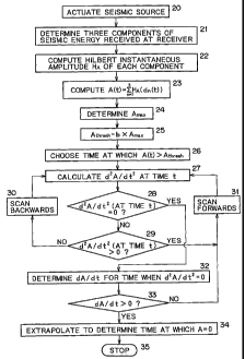
A preferred embodiment of the present invention is described schematically in
the flow
chart of Figure 7.
At step 20 a seismic source in a VSP seismic survey is actuated to emit a
pulse of
seismic energy. At step 21 the time-dependent amplitude traces of the three
components of the seismic energy received at a seismic receiver are recorded
and
stored. At step 22 the Hilbert instantaneous amplitude trace of each of the
input
components of the seismic energy is calculated, and at step 23 the three
Hilbert
instantaneous amplitudes are summed to determine the combined three-component
amplitude A(t) using equation (1). This is also stored.
At step 24 the maximum value of the combined three-component amplitude A(t) is
determined. At step 25 a threshold value Arhmh is determined from the value of
Aõ. in
this example by multiplying A,,,,,, by a predetermined constant b (i.e. using
equation (4)
above).
At step 26 a time is selected for which the instantaneous value of the three-
component
amplitude trace A(t) is greater than the threshold value Arh,.esh. The value,
at this selected
time, of the second derivative with respect to time of the combined three-
component
amplitude is then determined at step 27.
At step 28 it is tested whether the determined value of the second derivative
of A(t) at
the selected time is equal to zero. If the result of this determination is
"yes", this
indicates that the first derivative, with respect to time of A(t) is at a
maximum, and the
value of the first derivative of A(t) at this time is calculated at step 32,
and is stored. It is
checked at step 33 that the value of dA(t)/dt is positive; if the value of
dA(t)/dt is found
to be negative a new time is selected and steps 27 and 28 are repeated:
If it is found at step 28 that the second derivative of A(t) at the selected
time is not equal
to zero, at step 29 it is tested whether the second derivative of A(t) at the
selected time is
greater than zero. If the result of this determination is "yes", a new time,
greater than
the initial chosen time is selected at step 31, and steps 26, 27 and 28 are
repeated. If the
CA 02409041 2002-11-14
WO 01/88570 PCT/IB01/01108
result of the determination in step 29 is "no", a time earlier than the
initial chosen time
is selected at step 31, and steps 26, 27 and 28 are repeated. Steps 27 to 30
or 31 are
repeated until a "yes" deterniination is achieved at step 28.
Once a "yes" determination is achieved at box 28, the value of the first
derivative of the
three-component amplitude is calculated for the time at which its second
derivative is
zero is calculated at step 32. At step 33 it is checked whether the value if
the first
derivative is positive. If this step gives a "yes" determination, then the
calculated value
of the first derivative of the three component amplitude is known to be the
maximum
positive value of the gradient of the three-component amplitude. This value is
stored.
At step 34 the zero-crossing time is determined, by extrapolating backwards
from the
time at which the second derivative of the combined amplitude is zero, at the
determined value of the maximum gradient. The zero crossing time is then
stored.
The time picking step is then concluded at step 35. The results of the time
picking step
may then be used in further processing of the seismic data.
In the embodiment described in Figure 7, the combined three-component of the
seismic
data is computed at step 23 for the whole of the trace. In practice, an
operator may have
some idea of the likely arrival time of the direct pulse and, if so, it is not
necessary to
compute the three-component amplitude of the seismic data for the entire
trace. Instead,
it is sufficient to compute the three-component amplitude of the seismic data
for a time
range which includes the expected arrival time of the direct pulse, for
example the first
half of the trace. This reduces the amount of processing required, and so
reduces the
time taken to process the seismic data. If the three-component amplitude is
computed
only for a particular time range at step 23, it is of course only necessary at
step 22 to
compute the Hilbert instantaneous amplitude of each component for this time
range.
In the method shown in Figure 7, in step 26, the trace is scanned from time t=
0 to find
a point at which the total three-component amplitude exceeds the threshold
amplitude.
11
CA 02409041 2002-11-14
WO 01/88570 PCT/IB01/01108
However, if a trace contains noise at low times, a modified procedure can be
adopted to
reduce the possibility that this noise at low times will produce a spurious
time pick.
The modified procedure makes use of the parameter tnoise, which is chosen such
that the
trace contains only for times in the range 0< t<_ tõo;se. Rather than
processing data from
t = 0 in steps 22 and 23, the data is processed only for times t > tõoise,
thereby reducing
the amount of processing required.
In this embodiment it is possible to define an alternative threshold value for
A(t). This
is done by calculating the maximum amplitude of the noise signal, Amax-noise,
in the time
range up to tõoise. The alternative threshold for A(t) is then defined by:
A,j,resh = Amax-,to,se + b x (Amax - Aa=-noise ) (5)
In equation (5) b is again a constant selected by the operator.
Figure 6 shows results of applying the time picking method of the present
invention to a
three-dimensional VSP survey involving 21,240 source/receiver pairs. In each
case, the
offset between the source and the receiver was equal to or less than the depth
of the
receiver.
In Figure 6, each short line represents five source/receiver pairs. Two
surveys were
carried out, both in the same well. The results of one survey are shown in
black in
Figure 6, and the results of the other survey are shown in grey. A 99.4%
success rate is
estimated for the time picking step, based on a count of cases in which the
travel time
residual varies by less than lOOms from a calibrated one-dimensional model.
The methods of processing seismic data described above can be carried out
using any
conventional seismic data processing system. The processing is preferably
performed
on a data processor configured to process large amounts of data.
12
CA 02409041 2002-11-14
WO 01/88570 PCT/IB01/01108
Figure 8 illustrates a data processor suitable for performing the method of
the present
invention. The system comprises a programmable data processor 40 with a
programmable memory 41, for instance in the form of a read - only memory ROM,
storing a programme for controlling the data processor 40 to perform, for
example, the
method illustrated in Figure 7. The system further comprises non-volatile
read/write
memory 42 for storing, for example, any data which must be retained in the
absence of a
power supply. A "working" or "scratch pad" memory for the data processor is
provided
by a random access memory RAM 43. An input interface 44 is provided, for
instance
for receiving seismic data, either direct from a receiver data or via an
intermediate
storage mechanism such as magnetic tape or discs. An output interface 45 is
provided,
for instance for displaying and/or outputting the results of the data
processing.
While preferred embodiments of the present invention have been described
above, it
should be understood that the descriptions and drawings are only illustrative
of the
invention and are not intended to limit the scope of the present invention.
For example, in the preferred embodiment the time picking is carried out on a
combined
three-component amplitude derived from three components of the seismic energy
incident on the receiver. In principle, however, the time picking could be
carried out on
a combined amplitude generated from two components of the seismic data. This
can be
done, for example, by performing the summation in equation (1) for n = 1,2
only, rather
than for n= 1, 2 and 3 as in the embodiments described above.
The zero-crossing time picking method and the maximum gradient time picking
method
described above are not, in principle, limited to use on a combined two-
component or
three-component amplitude trace. In principle, these picking methods can be
applied to
conventional single-component traces.
13