Note: Descriptions are shown in the official language in which they were submitted.
CA 02409159 2002-11-14
- 1 -
DESCRIPTIONS
METHOD FOR MANUFACTURING HOT-DIP PLATED METAL STRIP AND
APPARATUS FOR MANUFACTURING THE SAME
i
TECHNICAL FIELD
The present invention relates to a method for manufacturing
a hot-dip plated metal strip and an apparatus for manufacturing
thereof .
BACKGROUND ART
Hot-dip plating is a known method of continuous plating
for a metal strip such as steel strip, which hot-dip plating method
conducts metal strip plating by immersing the metal strip in a
bath of molten metal of plating metal such,as zinc and aluminum,
(hereinafter referred to simply as "molten metal bath"). The
hot-dip plating method has many advantages such as allowing
manufacturing a plated steel strip at low cost compared with an
electroplating method and allowing easily manufacturing a plated
metal strip with thick coating layer.
Fig. 1 shows a conventional manufacturing line of hot-
dip plated metal strip.
The metal strip 1 which was rolled in the preceding step
of cold-rolling and was cleaned on the surface thereof in the
succeeding cleaning step is transferred to a hot-dip plated metal
strip manufacturing line, where the surface oxide film is removed
and the metal strip is annealed in an annealing furnace 71 which
CA 02409159 2002-11-14
- 2 -
is maintained in non-oxidizing or reducing atmosphere. Then,
the metal strip 1 is cooled to a temperature almost equal with
the temperature of a molten metal bath 2, and is introduced to
the molten metal bath 2 , where the molten metal is adhered onto
the surface of the metal strip 1. After that , the metal strip
1 is taken out from the molten metal bath 2, and a gas ejected
from a gas wiper 6 removes excess amount of molten metal adhered
to the metal strip 1 to ad just the plating weight of the molten
metal, thus to form the plating layer of the molten metal onto
the metal strip 1.
As shown in Fig . 2 , the metal strip 1 is introduced to the
molten metal bath 2 via a cylinder 4 called "snout" which is kept
to a non-oxidizing atmosphere therein, and the metal strip 1 is
turned the running direction in the molten metal bath 2 by a sink
roll 3 therein. Before being taken out from the molten metal
bath 2, the metal strip 1 is corrected in the warp generated in
width direction thereof and suppressed in the vibration thereof
by a stabilizing roll 79a and a correct roll 79b, (bath rolls
are collectively called "submersed support rolls 79").
The metal strip 1 coated with a plating layer is sub jected
to various treatments depending on the uses thereof to become
a final product. For example, when the metal strip 1 is used
as an external panel of automobile, the metal strip 1 is subjected
to alloying treatment of plating layer in an alloying furnace
9, and is introduced to a quenching zone 75, then is subjected
to special rust-preventive and corrosion-preventive treatment
in a conversion treatment unit 76.
CA 02409159 2002-11-14
- 3 -
The hot-dip plating method, however, has problems
described below.
1 ) An impurity called "dross" is generated in the molten
metal bath 2, which dross adheres to the metal strip 1 and to
the submersed support rolls 79 to become a defect of the metal
strip 1 reducing the yield thereof. To this point, high grade
hot-dip plated metal strip used in, for example, an automobile
external panel is processed at a low speed operation to prevent
the adhesion of dross. The countermeasure, however,
significantly degrades the productivity.
2) Since the submersed support rolls 79 are exposed to
severe environment of high temperatures, troubles such as
insufficient rotation likely occur, so that regular shut down
of the line is requested for maintenance and replacement of the
rolls, which degrades the productivity. ,In addition, these
troubles may cause defects such as dross adhesion to the metal
strip 1.
3) Owing to irregular rotational speed of the submersed
support rolls 79, irregular plating weight occurs to induce
chatter marks, which degrades the product quality.
DISCLOSURE OF THE INVENTION
An object of the present invention is to provide a method
and an apparatus for manufacturing high quality hot-dip plated
metal strip, allowing to prevent adhesion of dross without
degrading the productivity.
The object is attained by a method for manufacturing a
CA 02409159 2002-11-14
- 4 -
hot-dip plated metal strip, the method comprising the steps of
introducing a metal strip into a molten metal bath of plating
metal to adhere the molten metal onto a surface of the metal strip;
taking out the metal strip, after turning the running direction
thereof, from the molten metal bath without applying external
force from outside the surface of the metal strip; adjusting the
plating weight of the molten metal adhered onto the metal strip;
and controlling a shape of the metal strip using magnetic force
in non-contact state directly before or after the step of
adjust~.ng the plating weight.
The method is realized by an apparatus for manufacturing
a hot-dip plated metal strip, the apparatus comprising: a molten
metal bath containing a molten metal of plating metal and having
a unit for turning the running direction of the metal strip as
sole unit for applying external force thereto from outside the
surface of the metal strip; a wiper for adjusting the plating
weight of the molten metal adhered onto the metal strip; and a
control unit positioned directly before or after the-wiper to
control the shape of the metal strip using an electromagnet in
non-contact state.
BRIEF DESCRIPTION OF THE DRAWINGS
Fig. 1 illustrates a conventional manufacturing line of
hot-dip plated metal strip.
Fig. 2 illustrates a conventional molten metal bath.
Fig. 3 illustrates a mechanism of generating warp of metal
strip in the width direction thereof.
CA 02409159 2002-11-14
- 5 -
Fig. 4 illustrates a mechanism of correcting warp of metal
strip using submersed support rolls.
Fig. 5 illustrates an experimental apparatus for
investigating the effect of the submersed support rolls on the
quality of metal strip.
Fig. 6 illustrates a flow pattern of water in the vicinity
of a support roll.
Fig. 7 shows an example of shape control method for metal
strip using electromagnets.
Fig. 8A and Fig. 8B are graphs showing the relationship
between the warp, the thickness of metal strip, and the diameter
of sink roll.
Fig. 9 is a graph showing the relationship between the
diameter of sink roll and the maximum warp.
Fig. 10 illustrates an example of molten metal bath having
an open top enclosure.
Fig. 11 is a graph showing the relationship between the
warp, the thickness of metal strip, and the diameter of sink roll
in the presence of an open top enclosure.
Fig. 12 illustrates an example of open top enclosure
provided with a plate preventing dross from surfacing.
Fig. 13 illustrates an example of open top enclosure
provided with a streaming plate.
Fig. 14 illustrates another example of open top enclosure
provided with another streaming plate.
Fig. 15 illustrates an example of apparatus for
manufacturing a hot-dip plated metal strip according to the
CA 02409159 2002-11-14
- 6 -
present invention.
Fig. 16 illustrates another example of apparatus for
manufacturing a hot-dip plated metal strip according to the
present invention.
Fig. 17A and Fig. 17B illustrate further example of
apparatus for manufacturing a hot-dip plated metal strip
according to the present invention.
Fig. 18 illustrates still another example of apparatus for
manufacturing a hot-dip plated metal strip according to the
present invention.
Fig. 19 illustrates still further example of apparatus for
manufacturing a hot-dip plated metal strip according to the
present invention.
Fig. 20 illustrates an example of apparatus for
manufacturing a hot-dip plated metal strip,, provided with an open
top enclosure, according to the present invention.
Fig. 21 illustrates another example of apparatus for
manufacturing a hot-dip plated metal strip according~to the
present invention.
Fig. 22A and Fig. 22B show the relationship between the
distance at the moment that the metal strip leaves the sink roll
and the warp of the metal strip.
EMBODIMENTS OF THE INVENTION
The inventors studied the method for manufacturing a high
quality hot-dip plated metal strip that allowed to prevent
adhesion of dross without degrading the productivity, and found
CA 02409159 2002-11-14
that the removal of submersed support rolls and the control of
the shape of metal strip at a position of leaving the metal strip
from the molten metal bath in a non-contact state were extremely
effective. The detail of the method is described in the
following.
Fig. 3 illustrates a mechanism of generating warp on the
metal strip in the width direction thereof.
The warp of metal strip 1 in the width direction thereof
is presumably generated when the metal strip 1 is subjected to
bending and unbending mainly on the sink roll 3. That is, the
metal strip 1 is bent by being wound around the sink roll 3, then
is unbent by the sink roll 3 at a moment immediately before leaving
the sink roll 3 . Thus , the metal strip 1 receives tensile stress
on the face thereof contacting the sink roll 3, and receives
compression stress on the opposite face hereof. Accordingly,
at a position where the metal strip 1 leaves the sink roll 3 to
vanish the restriction force therefrom, the face of the metal
strip 1 contacting the sink roll 3 becomes free from the tensile
stress and is subjected to a force to return to original state,
while the opposite face of the metal strip 1 becomes free from
the compression stress and is sub jected to a force to return to
original state . As a result , the metal strip 1 is sub jected to
the resulting stress distribution to induce warp in the width
direction thereof to bend on both edges thereof toward the sink
roll 3.
When a warp is generated on the metal strip in that manner,
the gas wiper cannot perform the adjustment of coating weight
CA 02409159 2002-11-14
uniformly in the width direction of the metal strip 1 after leaving
the molten metal bath, thus inducing irregular plating weight
in the width direction of the metal strip.
When a warp is generated on the metal strip, there appears
a limitation in shortening the distance between the metal strip
and the gas wiper to avoid the contact between the metal strip
and the wiper. As a result, the wiping-gas pressure has to be
increased to assure a specified removal performance of molten
metal, which may induce a defect called "splash" (a phenomenon
that vigorously splashed molten metal during wiping action
adheres to the metal strip).
Consequently, the warp generated on the metal strip at the
sink roll has to be corrected by submersed support rolls.
Fig. 4 illustrates a mechanism of correcting warp of metal
strip using submersed support rolls.
The submersed support rolls consist of the stabilizing roll
79a and the correct roll 79b which is positioned below the
stabilizing roll 79a and is movable in horizontal direction. The
metal strip 1 is turned the running direction thereof by the sink
roll 3 upward in the molten metal bath 2. The stabilizing roll
79a is positioned to contact with the metal strip 1 which is turned
the running direction upward. The correct roll 79b is positioned
so as the metal strip 1 between the sink roll 3 and the stabilizing
roll 79a to be pushed in the normal direction to the metal strip
1 by a specified distance L.
As described above, a warp is generated on the metal strip
1 caused by bending and unbending induced by the sink roll 3.
CA 02409159 2002-11-14
_ g _
If, however, the correct roll 79b is used to adequately adjust
the distance L, a reverse directional bend is applied to the metal
strip 1 to correct the warp.
Generally, vibration on the metal strip is generated caused
by the unstable roll rotational frequency component induced by
incorrect rotation and looseness of sink roll and other
disturbance, and caused by excitation of natural frequency mode
of the metal strip itself.
As illustrated in Fig. 1, the conventional manufacturing
line of hot-dip plated metal strip very likely induces vibration
because the metal strip 1 is taken up from the molten metal bath
for a distance of several tens of meters without any support
thereto.
To this point, by restricting the metal strip 1 between
the submersed support rolls 79, as illustrated in Fig. 2, the
vibration is suppressed. For the case of Fig. 2, since the
submersed support rolls 79 create a node of vibration, the effect
of suppression of vibration at far above the molten metal bath
2 cannot be expected. However, the suppression of vibration at
the point of gas wiper 6, near the submersed support rolls 79,
is expected, so the irregularity in plating weight, which is the
most important variable in quality, can be reduced.
Thus, the submersed support rolls have long been applied
to correct the warp in the width direction of the metal strip
and to suppress the vibration of the metal strip, and, owing to
the field effects, the support rolls are accepted as an essential
device in the manufacturing line of hot-dip plated metal strip.
CA 02409159 2002-11-14
1~
Nevertheless, the use of submersed support rolls raises
several problems described below.
0 Impurities such as dross generated in molten metal bath
adhere to the metal strip. The submersed support rolls press
the impurities against the surface of the metal strip to induce
defects such as flaws .
When the correct roll is strongly pressed against the
metal strip for correcting warp in the width direction of the
metal strip, a defect called "break mark" is generated on the
metal strip.
Owing to the incorrect rotation or looseness of the
submersed support rolls themselves , the metal strip vibrates at
the gas wiper position to generate roll mark, which is a stripe
pattern defect, on the metal strip.
~ To conduct regular maintenance and replacement of the
submersed support rolls, the facility is required to shut-down,
which degrades the productivity and needs the maintenance cost .
Since these problems do not occur if the submersed support
rolls are absent, the inventors studied the elimination of
submersed support rolls in the hot-dip molten metal bath.
First , the inventors of the present invention studied the
influence of the elimination of submersed support rolls on the
quality of metal strip. In actual manufacturing, it is said that
the submersed support rolls have a function to prevent adhesion
of foreign matter such as dross in the molten metal bath to the
CA 02409159 2002-11-14
- 11 -
metal strip. Therefore, the elimination of the submersed support
rolls might increase the defects on the metal strip.
Fig. 5 illustrates an experimental apparatus for
investigating the effect of the submersed support rolls on the
quality of metal strip.
The experimental apparatus adopts water instead of molten
metal. A roll 80 and rolls 81 are placed in the water as a sink
roll and support rolls , respectively. An endless belt 82 is used
as the metal strip. Although water is adopted instead of the
molten metal, the roll diameter and the roll rotational speed
are selected to simulate the actual fluid dynamics behavior in
the molten metal bath in terms of Reynolds number and Froude number
around the rolls in the molten metal bath. Aluminum powder is
added to the water as a tracer to observe the flow of water.
Fig. 6 illustrates a flow pattern of ,water in the vicinity
of a support roll.
At a region beneath the contact point of the support roll
81 and the belt 82, there was observed a phenomenon that the
discharge flow caused by the pressure-increase pushes out the
foreign matter. On the other hand, at a region above the contact
point of the support roll 81 and the belt 82, a suction flow caused
by the pressure-decrease appeared to create a condition likely
allowing adhesion of foreign matter.
No action of removing foreign matter once adhered to the
belt 82 was observed on the support rolls 81, and the support
rolls 81 only acted to press the foreign matter against the belt
82.
CA 02409159 2002-11-14
- 12 -
From thus observed result, the inventors concluded that
the submersed support rolls have no function for .removing foreign
matter and that no increase in defects occurs even if the submersed
support rolls are eliminated. Therefore, to eliminate the
submersed support rolls, a means that can perform the function
to correct the warp in the width direction of the metal strip
and that can perform the function of suppressing vibration should
be provided.
An expecting means to perform these functions is to place
the submersed support rolls above the molten metal bath and to
position them between the level of the bath and the wiper. The
means, however, has problems described below.
1) The molten metal which is removed by the wiper is
oxidized to become dross of, for example, Zn0 and A1z03, which
dross is then pressed against the surface ,of metal strip by the
support rolls positioned above the bath to cause defects.
2 ) Since the distance between the bath level and the wiper
is generally about 400 to 500 mm, there is no space for qnounting
the support rolls.
In this regard, the inventors introduced the active control
technology as a substitute means. The active control technology
is a technology that uses an actuator to apply external force
to the control target based on the state of the target determined
by a sensor, thus making the shape of the target to a desired
shape and suppressing the vibration of the target. The
technology has shown wide applications owing to the drastic
increase in the computer capacity. The technology did not exist
CA 02409159 2002-11-14
- 13 -
at the time of developing conventional molten metal plating
technology. To apply the technology to the shape correction and
to the vibration suppression, the actuator may be controlled to
place the condition of flattening and of avoiding vibration for
the metal strip as the target condition. In that case, the
actuator is required to be able to apply force in non-contact
state for preventing defect generation on the metal strip.
Examples of the actuator are magnetic force actuator
(electromagnet) and pneumatic actuator (air pad).
For example, JP-A-7-102354, (the term "JP-A" referred
herein signifies the "unexamined Japanese patent publication"),
discloses a means for shape correction and for vibration
suppression of metal strip using a static pressure pad (pneumatic
actuator) which also functions as a gas ejection nozzle for
adjusting the plating weight. The means, however, has problems
such as : 1 ) use of pneumatic actuator positioned above the molten
metal bath may raise a problem of quality because unnecessary
cooling of the metal strip occurs caused by the gas flow; 2)
compared with electromagnet, the pneumatic actuator is large,
and needs wide space for installing accompanied piping and fan;
and 3) compared with electromagnet, the pneumatic actuator
consumes large electric power. According to the means disclosed
in JP-A-7-102354, the running passage of the metal strip is in
an arc shape. Consequently, if the gas ejection stops in case
of power failure or the like, the metal strip may collide with
the static pressure pad to induce serious line trouble.
Therefore, the pneumatic actuator is not suitable, and the
CA 02409159 2002-11-14
- 14 -
magnetic force actuator is required.
Thus, if the submersed support rolls are eliminated from
the molten metal bath, if no external force is applied from outside
the surface of the strip except for turning the running direction
of the metal strip in the molten metal bath, and if the shape
of the metal strip left from the molten metal bath is controlled
by magnetic force in non-contact state in the vicinity of the
wiper for adjusting plating weight, the adhesion of dross can
be prevented without degrading the productivity, and the plating
weight on the metal strip can be uniformized to manufacture high
quality hot-dip plated steel strip.
Fig . 7 shows an example of shape control method for metal
strip using electromagnets.
Along the surface of running metal strip 1, plurality of
position sensors 10 that determine the distance from the surface
of the metal strip 1 and plurality of electromagnets 13 that
control the shape of the metal strip 1 are located in non-contact
state. A controller 11 receives the signals sent from the
position sensors 10, and transmits the control signals to the
electromagnets 13 via amplifiers 12, thus correcting the warp
of the metal strip 1 using the suction force of the electromagnets
13. Three sets of position sensor 10 and electromagnet 13, at
both ends and center in the width direction of the metal strip
1, satisfactorily allow to correct the warp of the metal strip
1. The correction of warp is done to make the metal strip 1 flat
at the position of the wiper. For example, if an electromagnet
13 is positioned directly after the wiper, it is effective that
CA 02409159 2002-11-14
- 15 -
the electromagnet 13 applies a force so as the metal strip 1 to
give a warp inverse to the original warp.
Simultaneous control of the shape and the vibration on the
metal strip makes the plating weight of the molten metal more
uniform.
After the adjustment of plating weight of molten metal on
the metal strip, if rolls (support rolls outside the bath) are
brought into contact with the metal strip to control the vibration,
the vibration can be more surely prevented.
The metal strip after controlled the vibration by
contacting with the rolls may further be subjected to alloying
treatment for the plating layer.
The wiper for adjusting the plating weight may be an
electromagnetic wiper or the like, other than the above-described
gas wiper.
In the case that the submersed support rolls are eliminated
and are substituted by a non-contact control means, the space
in the molten metal bath can be utilized so that the optimization
of the diameter of sink roll and of the position of sink roll
can be established, as described below.
The maximum tensile stress Q generated in the uppermost
layer of the surface of the metal strip wound around a roll under
application of tension Qt is expressed by eq.(1)
Q= t x E x ( QY +QL)/(D xQy) (1)
where, t designates the thickness of metal strip, E
CA 02409159 2002-11-14
- 16 -
designates the Young's modulus of metal strip,QY is the yield
stress of metal strip, and D designates the roll diameter.
If the stress Q becomes equal to or above the yield stress
of the metal strip, the metal strip. presumably generates plastic
deformation, thus generating warp in the width direction thereof .
Accordingly, larger roll diameter D is more difficult in inducing
plastic deforming of the metal strip, resulting in smaller warp
in the width direction of the metal strip.
Fig. 8A and Fig. 8B are graphs showing the relationship
between the warp, the thickness of metal strip, and the diameter
of sink roll.
Fig. 8A and Fig. 8B give the relationship between the warp
and the thickness of metal strip per 1 m width at a tension of
3 kg/mmz and each of the sink roll diameters of 500, 750, and 900
mm. Fig. 8A is for a metal strip having the yield stress of 8
kg/mmz, and Fig. 8B is for a metal strip having the yield stress
of 14 kg/mmZ .
The figures suggest that the maximum warp is around -53
mm for the sink roll diameter of 500 mm, around -38 mm for the
sink roll diameter of 750 mm, and around -32 mm for the sink roll
diameter of 900 mm. If the warp is as large as -53 mm, it is
expected that, if no submersed support roll is applied, the warp
correction becomes difficult unless the output of the
electromagnet as the shape correction means is significantly
increased.
Fig. 9 is a graph showing the relationship between the
diameter of sink roll and the maximum warp.
CA 02409159 2002-11-14
- 17 -
If the sink roll diameter is 600 mm or more, the maximum
warp becomes around -46 mm or less, which allows reducing the
warp using an ordinary electromagnet . If the sink roll diameter
is 850 mm or more, the maximum warp becomes around -35 mm or less
so that smaller output of electromagnet can fully correct the
warp.
As for the vertical position of the sink roll in the molten
metal bath, a preferable distance between the upper end of the
sink roll and the level of the molten metal bath is between 50
and 400 mm. If the distance is less than 50 mm, the rotation
of sink roll disturbs the surface of the molten metal bath, which
makes the top dross consisting mainly of zinc oxide existing at
near the surface of the bath easily adhere to the metal strip.
If the distance exceeds 400 mm, the distance from next support
point, for example a roll located between the wiper above the
bath and the alloying furnace, or the distance from the support
roll outside the bath, increases, which increases the vibration
of metal strip, the warp at gas wiper section, and thequantity
of carrying molten metal. More preferably, the distance is from
100 to 200 mm.
The distance between the lower end of sink roll and the
bottom of the molten metal bath is preferably 400 mm or more from
the point of prevention of dross adhesion. More preferably, the
distance is 700 mm or more.
Dross which causes defects of a steel strip by adhering
thereto during hot-dip galvanizing is the bottom dross existing
CA 02409159 2002-11-14
I8
near the bottom of the bath. The bottom dross is an intermetallic
compound o~ zinc and iron which is eluted from the steel strip
in the molten zinc bath. The dross in the initial stage of
generation thereof is fine. The fine dross does not induce
significant problem in quality even if it adheres to the steel
strip. Since, however, the fine dross has higher density than
zinc, it sediments in the molten zinc bath to deposit. Once
deposited dross on the bottom of the molten zinc bath likely
surfaces carried by a flow of molten zinc accompanied with the
running steel strip. During repeated surfacing and sedimenting,
the fine dross coagulates owing to the variations in bath
temperature and to the variations in bath composition to become
coarse dross. The coarse dross floats along with the flow of
molten zinc, and likely induces defects of the steel strip by
adhering to the surface thereof . Increase in the running speed
of the steel strip increases the flow speed of the molten zinc,
which enhances the surfacing of dross to increase the generation
of defects on the steel strip.
Accordingly, to surely prevent the generation of defects
on the steel strip, it is necessary to prevent surfacing of dross
which sedimented to the bottom of the molten zinc bath. To do
this, it is necessary to prevent significant influence of the
running steel strip on the bottom portion of the molten zinc bath.
Also it is necessary that, even if the dross surfaces, the floating
dross does not adhere to the steel strip.
To this point , the inventors of the present invention found
that it was effective to separate the molten metal bath 2 to upper
CA 02409159 2002-11-14
- 19 -
and lower zones using an open top enclosure 8 which encloses the
sink roll 3 from lower side thereof , and to allow the molten metal
at above and beneath the open top enclosure 8 to flow therebetween,
which is illustrated in Fig. 10. Fig. 10 does not show the side
plates enclosing the sink roll 3 lateral to the axis of rotation
thereof. According to the present invention, no submersed
support roll is adopted, and thus there is much space in the molten
metal bath 2, so that the open top enclosure 8 can be
advantageously installed.
In a molten metal bath zone 2A above the open top enclosure
8 , the molten metal flows in arrow direction carried by the running
metal strip 1, and flows toward the zone beneath the open top
enclosure 8 from the side where the metal strip 1 is taken out
from the molten metal bath 2. In a molten metal bath zone 2B
beneath the open top enclosure 8, the molten metal flows upward
to above the open top enclosure 8 from the side where the metal
strip 1 is introduced to the molten metal bath 2. Thus the molten
metal forms a circulation flow.
If the metal strip 1 is a steel strip, and if the molten
metal is zinc, Fe elutes from the steel strip 1 in the molten
zinc bath zone 2A to form fine Fe-Zn base dross. A portion of
the fine dross adheres to the steel strip 1 to leave the molten
zinc bath zone 2A. Even when the fine dross adheres to the steel
strip 1, it does not raise quality problem. The fine dross that
was not removed from the molten zinc bath zone 2A is promptly
discharged to the zone beneath the open top enclosure 8 along
with the flow of molten zinc accompanied by the running steel
CA 02409159 2002-11-14
- 20 -
strip 1 from the side where the steel strip 1 is taken out from
the molten metal bath 2 in the open top enclosure 8.
The fine dross entered in the molten zinc bath zone 2B passes
through the area beneath the open top enclosure 8 , and moves to
the side where the steel strip 1 is introduced to the molten metal
bath 2 in the open top enclosure 8. The molten zinc bath zone
2B has larger capacity than the molten zinc bath zone 2A, and
is free from direct influence of the flow of molten zinc
accompanied with the running steel strip 1, so the flow of the
molten zinc in the molten zinc bath zone 2B is mild. As a result,
during a period of flowing the molten zinc entered in the molten
zinc bath zone 2B to a snout 4 , the dross existing in the molten
zinc sediments to the bottom portion of the molten zinc bath zone
2B to deposit. The deposited dross grows to coarse dross 17.
Since thus grown coarse dross 17 hardly surfaces even when the
running speed of the steel strip 1 varied, the molten zinc which
traveled through the molten zinc bath zone 2B and reached near
the snout 4 is free of dross.
The molten zinc free of dross enters the molten zinc bath
zone 2A from the top 8a of the side face of the open top enclosure
8 carried by the flow of molten zinc accompanied with the running
steel strip 1.
Consequently, no coarse dross 17 adheres to the steel strip
1 during the period of from introducing the steel strip 1 into
the molten metal bath 2 via the snout 4 to taking out from the
molten zinc bath 2.
The method of adopting the open top enclosure 8 establishes
CA 02409159 2002-11-14
- 21 -
the circulation flow of molten metal utilizing the flow of molten
metal accompanied with the running steel strip 1, without need
of additional driving means such as pump. Therefore, the method
is a simple and low cost one.
The open top enclosure 8 may be made of, for example,
stainless steel sheet.
As shown in Fig. 10, the open top enclosure 8 is preferably
located beneath the level of the molten metal bath 2 for the top
dross not to adhere to the side face of the open top enclosure
8. Alternatively, the open top enclosure 8 may be located in
such a way that the top edge thereof is above the level of the
molten metal bath. In that case, it is necessary that the side
face of the open top enclosure 8 has an opening to allow the molten
metal flowing therethrough.
In the case that the open top enclosure 8 is positioned
below the level of the molten metal bath 2 , if the depth of top
of the open top enclosure 8 becomes less than 100 mm from the
level of the molten metal bath 2, the flow of molten~metal
accompanied with the running steel strip 1 agitates the bath
surface to increase the generation of top dross. Therefore, it
is preferred that the top of the open top enclosure 8 is kept
to 100 mm or larger depth from the level of the molten metal bath .
It is preferable that the minimum distance between the open
top enclosure 8 and the sink roll 3 is 50 to 400 mm. If the distance
is less than 50 mm, the contact with thermally deformed metal
strip 1 may occur, and the installation of the open top enclosure
8 becomes difficult. If the distance exceeds 400 mm, there
CA 02409159 2002-11-14
- 22 -
appears a zone of no influence of the flow of molten metal
accompanied with the running metal strip l in the open top
enclosure 8 , which fails to discharge the dross generated in the
open top enclosure 8, and results in deposition of coarse dross
in the molten metal bath zone 2A.
It is preferable that the top edges 8a and 8b of both sides
of the open top enclosure 8 are so placed above the position of
shaft center of the sink roll 3 that the flow of molten metal
accompanied with the running metal strip 1 in the molten metal
bath zone 2A does not affect the flow of the molten metal in the
molten metal bath zone 2B, and that the coarse dross deposited
in the bottom portion of the molten metal bath zone 2B does not
surface. Furthermore, it is more preferable that the top edges
8a and 8b are above the top of sink roll 3.
It is preferable that the distance between the top 8a of
the side of the open top enclosure 8 at the snout 4 side and the
metal strip 1 is 1,000 mm or less. It is more preferable that
the distance is 800 mm or less. .
As shown in Fig. 11, even when the open top enclosure 8
exists, the relationship between the warp and the diameter of
sink roll is the same as that of the above-described case without
open top enclosure 8 , and it is preferable that the diameter of
sink roll is 850 mm or more.
The position of the sink roll is also preferably the one
in the above-described case without open top enclosure 8.
As shown in Fig. 10, if the side face of the open top
enclosure 8 at the side where the metal strip 1 is taken out from
CA 02409159 2002-11-14
- 23 -
the molten metal bath 2 is almost in parallel with the surface
of the metal strip 1, and if the top 8b of a side face of the
open top enclosure 8 is positioned at above the top of sink roll
3 , and at 100 mm or larger distance from the level of the molten
metal bath 2, the flow of the molten metal accompanied with the
running metal strip 1 can be kept at a high speed. As a result,
the molten metal in the molten metal bath zone 2A is efficiently
transferred to the molten metal bath zone 2B, and the adhesion
of dross to the metal strip can be effectively prevented.
As illustrated in Fig. 12, if the plate preventing dross
from surfacing 14 is located at the top 8b of a side face of the
open top enclosure 8 facing outside the open top enclosure 8,
the coarse dross deposited at the bottom portion of the molten
metal bath zone 2B is prevented from surfacing carried by the
molten metal entering from the molten metal bath zone 2A and from
adhering to the metal strip 1. From the viewpoint of suppressing
the disturbance of level of the molten metal bath 2, the plate
preventing dross from surfacing 14 is preferably tilted~downward
from the horizon. The plate preventing dross from surfacing 14
may be located at the top 8a of another side face of the open
top enclosure 8.
As illustrated in Fig. 13, if a streaming plate 15 is located
nearly in parallel with the bath level between the plate for
preventing dross from surfacing 14 positioned at the top 8b of
a side face of the open top enclosure 8 and the level of the molten
metal bath 2, the molten metal left from the molten metal bath
zone 2A easily flows into the molten metal bath zone 2B, and also
CA 02409159 2002-11-14
- 24 -
the disturbance of the level of molten metal bath 2 caused by
the flow of molten metal is prevented. It is preferred that the
streaming plate 15 is positioned as near the metal strip 1 as
possible for assuring smooth flow of molten metal . It is , however,
necessary that the streaming plate 15 is distant from the metal
strip 1 by 30 mm or more to avoid accidental contact with the
metal strip 1.
Fig . 14 illustrates an example of the streaming plate 16 ,
having another shape of the streaming plate from above. The
streaming plate 16 has a section nearly parallel with the face
of the metal strip, and is positioned at the place where the
support rolls are located in a conventional apparatus . With that
type of streaming plate 16, the dross adhesion is more surely
prevented.
The above-described method eliminates all the submersed
support rolls from the molten metal bath. Nevertheless, the
correction of warp and the suppression of vibration can be more
effectively conducted by leaving one submersed support~roll and
by letting the metal strip contact to the submersed support roll
after being turned its running direction by the sink roll. This
method, however, is more ineffective than the case of removing
all the submersed support rolls in terms of improvement of
productivity and of prevention of dross adhesion.
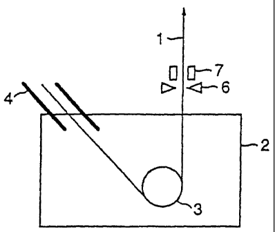
Fig. 15 illustrates an example of apparatus for
manufacturing a hot-dip plated metal strip according to the
CA 02409159 2002-11-14
- 25 -
present invention.
The metal strip 1 is introduced into the molten metal bath
2 via the snout 4 kept in a non-oxidizing atmosphere, turned the
running direction by the sink roll 3 , and then taken out upward
from the molten metal bath 2. The plating weight of the molten
metal as the plating metal adhered to the metal strip 1 during
the travel through the molten metal bath 2 is adjusted by the
gas wiper 6.
In the apparatus, no support roll which was adopted in a
conventional apparatus exists in the molten metal bath 2.
Instead of the support rolls, the control unit 7 for controlling
the shape and the vibration of the metal strip utilizing magnetic
force is positioned directly after the gas wiper 6 in a state
of non-contact with the metal strip 1. The term "directly after
the gas wiper 6° referred herein means a,position between the
gas wiper 6 and the alloying furnace which is described later.
The control unit 7 for controlling the shape and the vibration
of the metal strip can perform better shape control if ~the unit
7 is positioned as close to the gas wiper 6 as possible.
The control unit 7 for controlling the shape and the
vibration of the metal strip using magnetic force may allow the
control method for the shape and the vibration of metal strip
using electromagnets, shown in Fig. 7.
Exams a 2
Fig. 16 illustrates another example of apparatus for
manufacturing a hot-dip plated metal strip according to the
CA 02409159 2002-11-14
- 26 -
present invention.
In this apparatus , the control unit 7 for controlling the
shape and the vibration of the metal strip using magnetic force,
given in Fig. 15, is positioned directly before the gas wiper
6 in a state of non-contact with the metal strip 1. The term
"directly before the gas wiper 6" referred herein means a position
between the molten metal bath 2 and the gas wiper 6. The control
unit 7 for controlling the shape and the vibration of the metal
strip can perform better shape control if the unit 7 is positioned
as close to the gas wiper 6 as possible.
The control unit 7 for controlling the shape and the
vibration of the metal strip provides the same effect in either
case that the unit 7 is positioned directly before or that the
unit 7 is positioned directly after the gas wiper 6. However,
the position of directly before the gas wiper 6 and the position
directly after the gas wiper 6 have respective advantages
described below.
Directly before the gas wiper: Since nothing that~disturbs
the gas flow exists directly after the gas wiper 6, no quality
degradation occurs.
Directly after the gas wiper: No trouble occurs-on the
control unit caused by adhesion of molten metal that is removed
from the metal strip by gas wiping action.
Accordingly, the positioning of the control unit 7 for
controlling the shape and the vibration of the metal strip may
be selected taking into account of the advantages of each method
and of the conditions of manufacturing line such as a space.
CA 02409159 2002-11-14
- 27 -
Examyle 3
Fig. 17A and Fig. 17B illustrate further example of
apparatus for manufacturing a hot-dip plated metal strip
according to the present invention.
In this apparatus , two control units 7 for controlling the
shape and the vibration of the metal strip using magnetic force
are positioned at directly after the gas wiper 6 or at directly
before and after the gas wiper 6 in a state of non-contact with
the metal strip 1.
With the plurality of control units 7 for controlling the
shape and the vibration of the metal strip, the shape correction
or the vibration suppression is more effectively conducted.
Generally for the shape correction, since the change in
shape such as warp occurs slowly, the control system of the control
unit 7 for controlling the shape and the vibration of the metal
strip is not strongly requested to have followability. On the
other hand, for the vibration suppression, the variation of metal
strip 1 occurs quickly so that the control system of the control
unit 7 for controlling the shape and the vibration of the metal
strip is requested to have quick response ability. Regarding
the force required for the actuator, the shape correction
requires significantly strong force depending on the thickness
and the tension of the metal strip 1, while the vibration
suppression often requires only a force that can suppress
resonance of the metal strip 1. Accordingly, if , for example,
the actuator is an electromagnet, the number of coil windings,
CA 02409159 2002-11-14
- 28 -
the core shape, and other characteristics should be changed
depending on the shape correction service or on the vibration
suppression service.
Consequently, it is effective that plurality of control
units 7 is adopted and that work allotment is given to each control
unit 7 to perform mainly the shape correction and to perform mainly
the vibration suppression.
Example 4
Fig. 18 illustrates still another example of apparatus for
manufacturing a hot-dip plated metal strip according to the
present invention.
In the apparatus, the support rolls 83 outside the bath
to hold the metal strip 1 from two sides are positioned directly
after the control unit 7 for controlling,the shape and the
vibration of the metal strip using magnetic force shown in Fig.
15.
The support rolls 83 outside the bath are generally used
to stabilize the running of the metal strip 1 when is produced
the high grade hot-dip plated metal strip to be applied to, for
example, external panels of automobiles. Consequently, since
the present invention suppresses the vibration of metal strip
1 using the support rolls 83 outside the bath, the control unit
7 controlling the shape and the vibration of the metal strip mainly
conducts the shape correction. Even when accidentally large
vibration is generated, the support rolls 83 outside the bath
can prevent the influence of the vibration so that further stable
CA 02409159 2002-11-14
- 29 -
operation is attained.
It is not preferable that the support rolls 83 outside the
bath are positioned directly after wiping action in contact with
the metal strip 1. Nevertheless, when succeeding alloying
treatment is given in such a case of manufacturing a high grade
hot-dip plated metal strip, the contact with the support rolls
83 outside the bath raises very little problem.
When the direction of force applied from the metal strip
1 to the support rolls 83 outside the bath is considered, a single
support roll 83 outside the bath may be located at one side of
the metal strip 1. That is , if the control unit 7 for controlling
the shape and the vibration of the metal strip 1 applies a force
to the metal strip 1 to keep pressing thereof against a single
support roll 83 outside the bath, the contact point between the
support roll 83 outside the bath and the Lnetal strip 1 creates
a node of vibration, so that the vibration of the metal strip
1 can be suppressed.
E~ In a 5
Fig. 19 illustrates still further example of apparatus for
manufacturing a hot-dip plated metal strip according to the
present invention.
In the apparatus, the alloying furnace 9 is located after
the support rolls 83 shown in Fig. 18.
As described above, the alloying furnace 9 eliminates the
effect of the contact between the support rolls 83 and the metal
strip 1.
CA 02409159 2002-11-14
- 30 -
Exam,In a 6
An apparatus for manufacturing a hot-dip plated metal strip
having an open top enclosure as an example of the present invention,
shown in Fig. 20, was used to manufacture a hot-dip galvanized
steel strip 1 by continuously adhering molten zinc onto the steel
strip 1 having 1,200 mm in width and 1.0 mm in thickness at a
running speed of 90 mpm and a tension of 2 kg/cm2, and adjusting
the plating weight per side of the steel strip to 45 g/m2 using
the gas wiper 6.
The applied sink roll 3 had a diameter of 800 mm, and the
distance between the top of the sink roll 3 and the level of the
molten zinc bath 2 was about 600 mm. The open top enclosure 8
was located beneath the sink roll 3 to enclose the sink roll 3 ,
thus separating the molten zinc bath 2 to upper section and lower
section. The minimum distance between the open top enclosure
8 and the steel strip 1 was 150 mm.
Directly after the gas wiper 6 and at a distance of 1 to
20 m from the steel strip 1, there was located a control unit
7 for controlling the shape and the vibration of the steel strip
1, having electromagnets 13 , which apply magnetic force to the
steel strip 1, at three positions in the width direction of the
steel strip 1 so as to correct the warp of the steel strip 1 near
the gas wiper 6.
A sample having a size of 300 mm square was cut from the
hot-dip galvanized steel strip 1 to observe the surface thereof .
No dross was found on the sample. The deviation in plating weight
CA 02409159 2002-11-14
- 31 -
along the width of the steel strip 1 was determined to about ~
g/m2.
Similar test was conducted using the apparatus having no
open top enclosure 8, and ten positions of dross were found on
a 300 mm square sample. The deviation in plating weight along
the width of the steel strip 1 was determined to about + 5 g/m2 .
For comparison, an apparatus having conventional molten
metal bath shown in Fig. 2 was used to conduct similar tests.
Twenty positions of dross were found on a 300 mm square sample.
The deviation in plating weight along the width of the steel strip
1 was determined to about ~ 10 g/m2 .
The apparatus for manufacturing a hot-dip plated metal
strip, shown in Fig. 20, was used to manufacture a hot-dip
galvanized steel strip 1 by continuously adhering molten zinc
onto the steel strip 1 having 1,200 mm in width and 1.0 mm in
thickness at a running speed of 90 mpm and a tension of ~ kg/cm2,
and adjusting the plating weight per side of the steel strip to
45 g/m2 using the gas wiper 6.
The applied sink roll 3 had a diameter of 950 mm, and the
distance between the top of the sink roll 3 and the level of the
molten zinc bath 2 was about 200 mm. The minimum distance between
the open top enclosure 8 and the steel strip 1 was 100 mm.
The test similar to that of Example 6 was given to the steel
strip 1. No dross was found on the sample having a size of 300
mm square. The deviation in plating weight along the width of
CA 02409159 2002-11-14
- 32 -
the steel strip 1 was determined to about t5 g/m2.
Similar test was conducted with the apparatus having no
open top enclosure 8 , and fourteen positions of dross were found
on a 300 mm square sample. The deviation in plating weight along
the width of the steel strip 1 was determined to about ~4 g/mz.
For comparison, an apparatus having conventional molten
metal bath shown in Fig. 2 was used to conduct similar test.
Seventeen positions of dross were found on a 300 mm square sample.
The deviation in plating weight along the width of the steel strip
1 was determined to about t 10 g/m2 .
Example 8
Fig. 21 illustrates still other example of apparatus for
manufacturing a hot-dip plated metal strip according to the
present invention.
The apparatus corresponds to the apparatus shown in Fig.
18, which further contains one submersed support roll 5 in the
bath in addition to the support rolls 83 to press the metal strip
1 from two sides after the control unit 7 for controlling the
shape and the vibration of the metal strip in non-contact state .
As shown in Fig. 22A and Fig. 22B, the warp in width
direction of the steel strip 1 generated by plastic deformation
thereof caused by the sink roll 3 increases in the magnitude of
convexity with an increase in the distance from the sink roll
3, and becomes a constant magnitude at a certain distance.
Accordingly, if no submersed support roll 5 exists, the distance
between the sink roll 3 to which the metal strip 1 is not restricted
CA 02409159 2002-11-14
- 33 -
and the gas wiper 6 becomes longer than the distance between the
sink roll 3 to which the metal strip 1 is not restricted and the
gas wiper 6 in the case of existence of the submersed support
roll 5. Consequently, the warp of the metal strip becomes large,
which requires to increase the correction force necessary to
flatten the metal strip 1 at the position of the gas wiper 6.
Therefore, it is possible to minimize the correction force
(for example, supply current for the case of electromagnet)
necessary to flatten the metal strip 1 at the position of the
gas wiper 6 by installing a single submersed support roll 5 in
the bath to press thereof against the metal strip 1 to apparently
eliminate the warp.
Furthermore, since there is only one submersed support roll,
there are few differences from the conventional method, thus the
present invention can be applied without significantly changing
the conventional operational conditions. Consequently, the
example is the first step for moving to the case without using
submersed support roll.
The submersed support roll 5 is not limited to the position
given in Fig. 21, and may be positioned so as to contact with
the surface of the metal strip 1 at the sink roll 3 side. Also
for the case of applying submersed support roll 5, variations
of auxiliary units shown in Figs . 16 through 19 may be applied.