Language selection

Search

Patent 2409473 Summary

Third-party information liability

Some of the information on this Web page has been provided by external sources. The Government of Canada is not responsible for the accuracy, reliability or currency of the information supplied by external sources. Users wishing to rely upon this information should consult directly with the source of the information. Content provided by external sources is not subject to official languages, privacy and accessibility requirements.

Claims and Abstract availability

Any discrepancies in the text and image of the Claims and Abstract are due to differing posting times. Text of the Claims and Abstract are posted:

  • At the time the application is open to public inspection;
  • At the time of issue of the patent (grant).
(12) Patent: (11) CA 2409473
(54) English Title: MOWER-CONDITIONER
(54) French Title: FAUCHEUSE-CONDITIONNEUSE
Status: Expired and beyond the Period of Reversal
Bibliographic Data
(51) International Patent Classification (IPC):
  • A01D 43/00 (2006.01)
  • A01D 82/00 (2006.01)
(72) Inventors :
  • MELLIN, MICHAEL JAMES (France)
(73) Owners :
  • DEERE & COMPANY
(71) Applicants :
  • DEERE & COMPANY (United States of America)
(74) Agent: BORDEN LADNER GERVAIS LLP
(74) Associate agent:
(45) Issued: 2006-07-11
(22) Filed Date: 2002-10-23
(41) Open to Public Inspection: 2003-04-30
Examination requested: 2002-10-23
Availability of licence: N/A
Dedicated to the Public: N/A
(25) Language of filing: English

Patent Cooperation Treaty (PCT): No

(30) Application Priority Data:
Application No. Country/Territory Date
101 53 564.3 (Germany) 2001-10-30

Abstracts

English Abstract


A mower conditioner includes upper and lower conditioner rolls with the upper
roll extending between, and being rotatably mounted to, a pair of vertically
swingable
arms. A linkage arrangement is coupled between the frame supporting the arms
and
the arms, with one part of the linkage being associated with a stop for
limiting the
range of movement of the upper roll toward the lower roll, and with another
part of the
linkage being coupled to a spring arrangement for biasing the upper roll
toward the
lower roll. The stop is configured as a pair of wedge-shaped members having
respective inclined surfaces engaged with each other and held in an adjusted
position
by a nut and bolt arrangement, the range of movement of the upper roll toward
the
lower roll changing in response to tightening or loosening the nut on the
bolt.


Claims

Note: Claims are shown in the official language in which they were submitted.

CLAIMS:
1. In a mower-conditioner including a housing having opposite sides
rotatably supporting a first conditioner roll extending between said opposite
sides,
a second conditioner roll extending between said opposite sides and having
opposite
ends respectively rotatably mounted in a pair of arms which are respectively
pivotally
mounted to said opposite sides for guiding said second conditioner roll along
an
arcuate path toward and away from said first conditioner roil, a stop
arrangement
being coupled to said pair of arms and being adjustable for forming a minimum
gap of
a desired size between said first and second conditioner rolls through which
harvested
crop is conducted for being conditioned, the improvement comprising: said stop
arrangement including at least one wedge-shaped element that can be
repositioned
transverse to said arcuate path for changing the size of said desired gap.
2. The mower-conditioner, as defined in claim 1, wherein said stop
arrangement includes two wedge-shaped elements that are arranged so as to
slide
against each other.
3. The mower-conditioner, as defined in claim 1, and further including a
threaded element engaging said at least one wedge-shaped element for
selectively
repositioning said wedge-shaped element in response to turning said threaded
element.
4. The mower-conditioner, as defined in claim 1, wherein a linkage is
coupled between one of said pair of arms and said at least one wedge-shaped
element, with said linkage including a forked shape end having legs straddling
said
wedge shaped element; and a pin extending between, and being received in, said
legs
and being positioned for engaging said wedge-shaped element.
5. A stop for use in limiting the range of movement of a movable upper
roll of a mower-conditioner, comprising: two wedge-shaped elements having
respective first and second surfaces inclined from horizontal and being
engaged with
each other; said two wedge elements respectively having first and second
support
surfaces which are parallel to each other when said first and second surfaces
are
engaged with each other; and a threaded element being associated with said two
wedge elements for repositioning the two wedge elements relative to each other
in
response to turning said threaded element and thereby changing the distance
between said first and second support surfaces.
5

Description

Note: Descriptions are shown in the official language in which they were submitted.


CA 02409473 2005-06-27
MOWER-CONDITIONER
Field of the Invention
The invention concerns a mower-conditioner with at least one roll for the
conditioning of harvested crop being adjustable relative to another roll for
defining a
desired gap therebetween through which crop is conducted, the gap being
determined
by an adjustable stop.
Backgiround of the Invention
US-A-5,033,257 and US-A-4,472,927 each disclose a mower-conditioner with
two rolls rotating in opposite directions that leave a gap between them
through which
the harvested crop is conducted and is conditioned on the basis of the
mechanical
action of the profiled rolls. In order to adjust the height of the gap, the
upper roll is
supported in bearings at each end in a pivot arm, whose lower end position is
determined by means of a linkage. For this purpose, the linkage is provided
with a
threaded region at the end region opposite the pivot arm to which one or more
nuts
may be applied that can be brought into contact with a stop formed on the
housing
of the mower-conditioner.
The problem underlying the invention is that the threaded connection between
the nut and the threaded region is heavily loaded and becomes damaged after
extended use due the constant spring load resisting upward movement of the
roll, so
that the position of the nut can hardly be adjusted.
Summaryof the Invention
This problem is solved by providing an adjustable stop arrangement defined by
an adjustable wedge arrangement for determining the minimum roll gap.
The effective position of the stop is determined by the thickness of the wedge
arrangement which is adjustable so as to vary its thickness and which is
oriented
and coupled to the moveable conditioning roll in a manner devoid of threads so
that
spring forces acting on the movable conditioning roll are borne by the stop.
Consequently, a readjustment of the stop can be performed without any
problems.
A parallel adjustment of the support surfaces, even with increased slope, is
achieved by the use of two wedge-shaped elements that slide upon each other
with
their inclined surfaces and thereby increase or reduce the spacing of the
support
surfaces. The repositioning can be performed in steps by the use of
projections,
hooks, recesses or the like, or performed without any steps.
A repositioning without any steps is possible among others if a screw is
guided

CA 02409473 2002-10-23
tlhrough and is brought into contact with it and is retained in a threaded
hole in the
other element. In place of a screw, a threaded bushing or the like could also
be
used.
A possibility exists in the readjustment of the width of the gap (preferably 2
to
5mm.) from an easily accessible location by supporting each end of the roll in
a pivot
arm to connect the pivot arms in each case with a linkage and to retain the
linkages
by means of a suspension in, at or on the stop relative to a frame or housing
of the
mower-conditioner. The linkage can be configured as a simple rod or strut, as
a
steel cable, a chain or the like.
According to another method, the stop is brought directly into the pivoting
region
of the pivot arm. In this case, one as well as two wedge-shaped elements may
be
used.
The linkage can be securely retained at the stop if it is configured in a
forked
shape and penetrates the stop where its ends are connected by means of a pin
or
the like.
The reliability and/or service friendliness of known mower-conditioners can be
innproved if a stop according to the state of the art is replaced by a stop
with one or
tvvo wedge-shaped elements, whose slope is used for a repositioning transverse
to
the direction of movement of the roll.
Brief Description of the Drawincts
The drawing shows an embodiment of the invention that shall be described in
greater detail in the following.
FIG. 1 shows a somewhat schematic, left side view of a mower-conditioner with
a
conditioning arrangement.
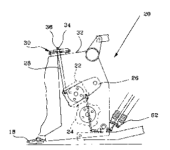
FIG. 2 shows an enlarged side view of the conditioning arrangement with an
adjustable stop.
FIG. 3 shows an enlarged view of the adjustable stop.
Description of the Preferred Embodiment
FIG. 1 shows a mower-conditioner 10 in a configuration known in itself with a
frame 12, a running gear 14, a towbar 16, a mower head 18, and a conditioning
arrangement 20.
2

CA 02409473 2002-10-23
According to FIG. 2, the conditioning arrangement 20 contains an upper and a
lower roll 22 and 24, respectively, each of which is provided with a congruent
outer
profile, that leaves a small gap between them through which harvested crop
coming
from the mower head 18 is conducted and thereby is crushed for conditioning.
While
the lower roll 24 is supported in stationary bearings, but free to rotate, the
upper roll
22 is engaged at each end in a pivot arm 26 so that it can move vertically
under
spring force relative to the lower roll 24.
For the adjustment of the gap or the contact pressure of the upper roll 22
against
the lower roll 24, a linkage 28 is provided on each side of the conditioning
arrangement 20 that is connected in its lower region, free to pivot, with the
pivot arm
26 and that is brought into contact at its upper end region with a stop 30,
that is
connected with a housing 32 of the conditioning arrangement 20. In its upper
end
region, the linkage 28 is configured with a forked end where two legs 34 of
the forked
end are bridged by a pin 36.
In this embodiment, the stop 30 is composed of two wedge-shaped elements 38.
In this embodiment, each element 38 is configured in the side view as a right
triangle
and therefore contains a surface 40 corresponding to a hypotenuse, a contact
surface 42 in the vertical direction corresponding to a cathetus, and a
support
surface 44 corresponding to a horizontal cathetus. A bore 46 extends through
each
element 38 that is generally in the center and vertical to the contact surface
42. A
recess 48 extends through each element 38 that is generally central and
vertical to
the support surface 44.
In the installed condition, the elements 38 are indexed through 180° to
each other
and the surfaces 40 are in contact with each other. A threaded element 50
extends
through the bores 46, particularly in the form of a screw or a threaded rod.
The
outside diameter of the threaded element 50 is considerably less than the
inside
diameter of the bore 46. As can be seen in FIG. 3, the threaded element 50 has
a
head 52 in contact with the right contact surface 42 and receives a nut 54 on
its left
end, which is in contact with the corresponding contact surface 42. The nut 54
may
be configured as a locknut, or it may be secured with a jam nut. The lower
element
38 is preferably fastened to the housing 32, but this is not mandatory.
3

CA 02409473 2002-10-23
The recess 48 is selected so that it is sufficiently large that it can leave
enough
free space for the penetration of the legs 34 of the linkage 28 alongside the
threaded
element 50, particularly within a limited adjustment region of the elements
38. The
necessary free space is a function of the shape of the legs 34, so that, for
example, if
the legs 34 are formed of flat steel, the recess 48 can be held to a smaller
size than
that for the legs 34 formed of cylindrical steel bars.
The linkage 28 is mounted on, at, or in the stop 30 in such a way that the
legs 34
penetrate through the free spaces on both sides of the threaded element 50
within
the recess 48 up to a point under the upper element 38 and beyond that and is
connected there with the pin 36. The pin 36 can be secured in its position by
a
thread and also by cotter pins.
As can be seen from the preceding description, but also with a view of FIG. 3,
a
rotation of the nut 54 results in a repositioning of the elements 38 relative
to each
other. A repositioning of the elements 38 has the result of changing the
distance
between the two support surfaces 44, which in turn leads to a vertical
movement of
the pin 36, and with it, the linkage 28. A repositioning of the linkage 28 at
both ends
of the upper roll 22 has the result that the distance between the rolls 22 and
24 is
changed or the contact pressure of the upper roll 22 upon the lower roll 24 is
changed. The forces originating from the upper roll 22 are transmitted over
the
support surfaces 44 and the surFaces 40 to the elements 38, while the threaded
element 50 remains essentially unloaded on the basis of the small horizontal
vector.
It can be seen that the forces in the threaded element 50 are directly
proportional to
the inclination of the surfaces 40.
In another embodiment, not shown, a stop is fastened in one or two wedge-
shaped elements to the housing 32 in such a way that the underside of the
pivot arm
2Ei can be brought into contact with it. In this embodiment, the wedge-shaped
element or elements are also shifted by means of a threaded element.
Having described the preferred embodiment, it will become apparent that
various
modifications can be made without departing from the scope of the invention as
defined in the accompanying claims.
4

Representative Drawing
A single figure which represents the drawing illustrating the invention.
Administrative Status

2024-08-01:As part of the Next Generation Patents (NGP) transition, the Canadian Patents Database (CPD) now contains a more detailed Event History, which replicates the Event Log of our new back-office solution.

Please note that "Inactive:" events refers to events no longer in use in our new back-office solution.

For a clearer understanding of the status of the application/patent presented on this page, the site Disclaimer , as well as the definitions for Patent , Event History , Maintenance Fee  and Payment History  should be consulted.

Event History

Description Date
Time Limit for Reversal Expired 2010-10-25
Letter Sent 2009-10-23
Grant by Issuance 2006-07-11
Inactive: Cover page published 2006-07-10
Pre-grant 2006-04-24
Inactive: Final fee received 2006-04-24
Inactive: IPC from MCD 2006-03-12
Notice of Allowance is Issued 2005-11-02
Letter Sent 2005-11-02
Notice of Allowance is Issued 2005-11-02
Inactive: Approved for allowance (AFA) 2005-10-24
Amendment Received - Voluntary Amendment 2005-06-27
Inactive: S.30(2) Rules - Examiner requisition 2005-01-10
Inactive: S.29 Rules - Examiner requisition 2005-01-10
Application Published (Open to Public Inspection) 2003-04-30
Inactive: Cover page published 2003-04-29
Inactive: First IPC assigned 2003-01-16
Inactive: Filing certificate - RFE (English) 2002-12-11
Letter Sent 2002-12-11
Application Received - Regular National 2002-12-11
Request for Examination Requirements Determined Compliant 2002-10-23
All Requirements for Examination Determined Compliant 2002-10-23

Abandonment History

There is no abandonment history.

Maintenance Fee

The last payment was received on 2005-10-07

Note : If the full payment has not been received on or before the date indicated, a further fee may be required which may be one of the following

  • the reinstatement fee;
  • the late payment fee; or
  • additional fee to reverse deemed expiry.

Patent fees are adjusted on the 1st of January every year. The amounts above are the current amounts if received by December 31 of the current year.
Please refer to the CIPO Patent Fees web page to see all current fee amounts.

Fee History

Fee Type Anniversary Year Due Date Paid Date
Application fee - standard 2002-10-23
Request for examination - standard 2002-10-23
Registration of a document 2002-10-23
MF (application, 2nd anniv.) - standard 02 2004-10-25 2004-10-05
MF (application, 3rd anniv.) - standard 03 2005-10-24 2005-10-07
Final fee - standard 2006-04-24
MF (patent, 4th anniv.) - standard 2006-10-23 2006-10-02
MF (patent, 5th anniv.) - standard 2007-10-23 2007-10-01
MF (patent, 6th anniv.) - standard 2008-10-23 2008-09-30
Owners on Record

Note: Records showing the ownership history in alphabetical order.

Current Owners on Record
DEERE & COMPANY
Past Owners on Record
MICHAEL JAMES MELLIN
Past Owners that do not appear in the "Owners on Record" listing will appear in other documentation within the application.
Documents

To view selected files, please enter reCAPTCHA code :


To view images, click a link in the Document Description column. To download the documents, select one or more checkboxes in the first column and then click the "Download Selected in PDF format (Zip Archive)" or the "Download Selected as Single PDF" button.

List of published and non-published patent-specific documents on the CPD .

If you have any difficulty accessing content, you can call the Client Service Centre at 1-866-997-1936 or send them an e-mail at CIPO Client Service Centre.


Document
Description 
Date
(yyyy-mm-dd) 
Number of pages   Size of Image (KB) 
Abstract 2002-10-22 1 23
Description 2002-10-22 4 216
Claims 2002-10-22 2 69
Drawings 2002-10-22 2 40
Representative drawing 2003-01-16 1 9
Claims 2005-06-26 1 59
Description 2005-06-26 4 216
Acknowledgement of Request for Examination 2002-12-10 1 174
Courtesy - Certificate of registration (related document(s)) 2002-12-10 1 106
Filing Certificate (English) 2002-12-10 1 159
Reminder of maintenance fee due 2004-06-24 1 111
Commissioner's Notice - Application Found Allowable 2005-11-01 1 161
Maintenance Fee Notice 2009-12-06 1 170
Correspondence 2006-04-23 1 33