Sélection de la langue

Search

Sommaire du brevet 2409473 

Énoncé de désistement de responsabilité concernant l'information provenant de tiers

Une partie des informations de ce site Web a été fournie par des sources externes. Le gouvernement du Canada n'assume aucune responsabilité concernant la précision, l'actualité ou la fiabilité des informations fournies par les sources externes. Les utilisateurs qui désirent employer cette information devraient consulter directement la source des informations. Le contenu fourni par les sources externes n'est pas assujetti aux exigences sur les langues officielles, la protection des renseignements personnels et l'accessibilité.

Disponibilité de l'Abrégé et des Revendications

L'apparition de différences dans le texte et l'image des Revendications et de l'Abrégé dépend du moment auquel le document est publié. Les textes des Revendications et de l'Abrégé sont affichés :

  • lorsque la demande peut être examinée par le public;
  • lorsque le brevet est émis (délivrance).
(12) Brevet: (11) CA 2409473
(54) Titre français: FAUCHEUSE-CONDITIONNEUSE
(54) Titre anglais: MOWER-CONDITIONER
Statut: Périmé et au-delà du délai pour l’annulation
Données bibliographiques
(51) Classification internationale des brevets (CIB):
  • A01D 43/00 (2006.01)
  • A01D 82/00 (2006.01)
(72) Inventeurs :
  • MELLIN, MICHAEL JAMES (France)
(73) Titulaires :
  • DEERE & COMPANY
(71) Demandeurs :
  • DEERE & COMPANY (Etats-Unis d'Amérique)
(74) Agent: BORDEN LADNER GERVAIS LLP
(74) Co-agent:
(45) Délivré: 2006-07-11
(22) Date de dépôt: 2002-10-23
(41) Mise à la disponibilité du public: 2003-04-30
Requête d'examen: 2002-10-23
Licence disponible: S.O.
Cédé au domaine public: S.O.
(25) Langue des documents déposés: Anglais

Traité de coopération en matière de brevets (PCT): Non

(30) Données de priorité de la demande:
Numéro de la demande Pays / territoire Date
101 53 564.3 (Allemagne) 2001-10-30

Abrégés

Abrégé anglais


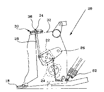
A mower conditioner includes upper and lower conditioner rolls with the upper
roll extending between, and being rotatably mounted to, a pair of vertically
swingable
arms. A linkage arrangement is coupled between the frame supporting the arms
and
the arms, with one part of the linkage being associated with a stop for
limiting the
range of movement of the upper roll toward the lower roll, and with another
part of the
linkage being coupled to a spring arrangement for biasing the upper roll
toward the
lower roll. The stop is configured as a pair of wedge-shaped members having
respective inclined surfaces engaged with each other and held in an adjusted
position
by a nut and bolt arrangement, the range of movement of the upper roll toward
the
lower roll changing in response to tightening or loosening the nut on the
bolt.

Revendications

Note : Les revendications sont présentées dans la langue officielle dans laquelle elles ont été soumises.


CLAIMS:
1. In a mower-conditioner including a housing having opposite sides
rotatably supporting a first conditioner roll extending between said opposite
sides,
a second conditioner roll extending between said opposite sides and having
opposite
ends respectively rotatably mounted in a pair of arms which are respectively
pivotally
mounted to said opposite sides for guiding said second conditioner roll along
an
arcuate path toward and away from said first conditioner roil, a stop
arrangement
being coupled to said pair of arms and being adjustable for forming a minimum
gap of
a desired size between said first and second conditioner rolls through which
harvested
crop is conducted for being conditioned, the improvement comprising: said stop
arrangement including at least one wedge-shaped element that can be
repositioned
transverse to said arcuate path for changing the size of said desired gap.
2. The mower-conditioner, as defined in claim 1, wherein said stop
arrangement includes two wedge-shaped elements that are arranged so as to
slide
against each other.
3. The mower-conditioner, as defined in claim 1, and further including a
threaded element engaging said at least one wedge-shaped element for
selectively
repositioning said wedge-shaped element in response to turning said threaded
element.
4. The mower-conditioner, as defined in claim 1, wherein a linkage is
coupled between one of said pair of arms and said at least one wedge-shaped
element, with said linkage including a forked shape end having legs straddling
said
wedge shaped element; and a pin extending between, and being received in, said
legs
and being positioned for engaging said wedge-shaped element.
5. A stop for use in limiting the range of movement of a movable upper
roll of a mower-conditioner, comprising: two wedge-shaped elements having
respective first and second surfaces inclined from horizontal and being
engaged with
each other; said two wedge elements respectively having first and second
support
surfaces which are parallel to each other when said first and second surfaces
are
engaged with each other; and a threaded element being associated with said two
wedge elements for repositioning the two wedge elements relative to each other
in
response to turning said threaded element and thereby changing the distance
between said first and second support surfaces.
5

Description

Note : Les descriptions sont présentées dans la langue officielle dans laquelle elles ont été soumises.


CA 02409473 2005-06-27
MOWER-CONDITIONER
Field of the Invention
The invention concerns a mower-conditioner with at least one roll for the
conditioning of harvested crop being adjustable relative to another roll for
defining a
desired gap therebetween through which crop is conducted, the gap being
determined
by an adjustable stop.
Backgiround of the Invention
US-A-5,033,257 and US-A-4,472,927 each disclose a mower-conditioner with
two rolls rotating in opposite directions that leave a gap between them
through which
the harvested crop is conducted and is conditioned on the basis of the
mechanical
action of the profiled rolls. In order to adjust the height of the gap, the
upper roll is
supported in bearings at each end in a pivot arm, whose lower end position is
determined by means of a linkage. For this purpose, the linkage is provided
with a
threaded region at the end region opposite the pivot arm to which one or more
nuts
may be applied that can be brought into contact with a stop formed on the
housing
of the mower-conditioner.
The problem underlying the invention is that the threaded connection between
the nut and the threaded region is heavily loaded and becomes damaged after
extended use due the constant spring load resisting upward movement of the
roll, so
that the position of the nut can hardly be adjusted.
Summaryof the Invention
This problem is solved by providing an adjustable stop arrangement defined by
an adjustable wedge arrangement for determining the minimum roll gap.
The effective position of the stop is determined by the thickness of the wedge
arrangement which is adjustable so as to vary its thickness and which is
oriented
and coupled to the moveable conditioning roll in a manner devoid of threads so
that
spring forces acting on the movable conditioning roll are borne by the stop.
Consequently, a readjustment of the stop can be performed without any
problems.
A parallel adjustment of the support surfaces, even with increased slope, is
achieved by the use of two wedge-shaped elements that slide upon each other
with
their inclined surfaces and thereby increase or reduce the spacing of the
support
surfaces. The repositioning can be performed in steps by the use of
projections,
hooks, recesses or the like, or performed without any steps.
A repositioning without any steps is possible among others if a screw is
guided

CA 02409473 2002-10-23
tlhrough and is brought into contact with it and is retained in a threaded
hole in the
other element. In place of a screw, a threaded bushing or the like could also
be
used.
A possibility exists in the readjustment of the width of the gap (preferably 2
to
5mm.) from an easily accessible location by supporting each end of the roll in
a pivot
arm to connect the pivot arms in each case with a linkage and to retain the
linkages
by means of a suspension in, at or on the stop relative to a frame or housing
of the
mower-conditioner. The linkage can be configured as a simple rod or strut, as
a
steel cable, a chain or the like.
According to another method, the stop is brought directly into the pivoting
region
of the pivot arm. In this case, one as well as two wedge-shaped elements may
be
used.
The linkage can be securely retained at the stop if it is configured in a
forked
shape and penetrates the stop where its ends are connected by means of a pin
or
the like.
The reliability and/or service friendliness of known mower-conditioners can be
innproved if a stop according to the state of the art is replaced by a stop
with one or
tvvo wedge-shaped elements, whose slope is used for a repositioning transverse
to
the direction of movement of the roll.
Brief Description of the Drawincts
The drawing shows an embodiment of the invention that shall be described in
greater detail in the following.
FIG. 1 shows a somewhat schematic, left side view of a mower-conditioner with
a
conditioning arrangement.
FIG. 2 shows an enlarged side view of the conditioning arrangement with an
adjustable stop.
FIG. 3 shows an enlarged view of the adjustable stop.
Description of the Preferred Embodiment
FIG. 1 shows a mower-conditioner 10 in a configuration known in itself with a
frame 12, a running gear 14, a towbar 16, a mower head 18, and a conditioning
arrangement 20.
2

CA 02409473 2002-10-23
According to FIG. 2, the conditioning arrangement 20 contains an upper and a
lower roll 22 and 24, respectively, each of which is provided with a congruent
outer
profile, that leaves a small gap between them through which harvested crop
coming
from the mower head 18 is conducted and thereby is crushed for conditioning.
While
the lower roll 24 is supported in stationary bearings, but free to rotate, the
upper roll
22 is engaged at each end in a pivot arm 26 so that it can move vertically
under
spring force relative to the lower roll 24.
For the adjustment of the gap or the contact pressure of the upper roll 22
against
the lower roll 24, a linkage 28 is provided on each side of the conditioning
arrangement 20 that is connected in its lower region, free to pivot, with the
pivot arm
26 and that is brought into contact at its upper end region with a stop 30,
that is
connected with a housing 32 of the conditioning arrangement 20. In its upper
end
region, the linkage 28 is configured with a forked end where two legs 34 of
the forked
end are bridged by a pin 36.
In this embodiment, the stop 30 is composed of two wedge-shaped elements 38.
In this embodiment, each element 38 is configured in the side view as a right
triangle
and therefore contains a surface 40 corresponding to a hypotenuse, a contact
surface 42 in the vertical direction corresponding to a cathetus, and a
support
surface 44 corresponding to a horizontal cathetus. A bore 46 extends through
each
element 38 that is generally in the center and vertical to the contact surface
42. A
recess 48 extends through each element 38 that is generally central and
vertical to
the support surface 44.
In the installed condition, the elements 38 are indexed through 180° to
each other
and the surfaces 40 are in contact with each other. A threaded element 50
extends
through the bores 46, particularly in the form of a screw or a threaded rod.
The
outside diameter of the threaded element 50 is considerably less than the
inside
diameter of the bore 46. As can be seen in FIG. 3, the threaded element 50 has
a
head 52 in contact with the right contact surface 42 and receives a nut 54 on
its left
end, which is in contact with the corresponding contact surface 42. The nut 54
may
be configured as a locknut, or it may be secured with a jam nut. The lower
element
38 is preferably fastened to the housing 32, but this is not mandatory.
3

CA 02409473 2002-10-23
The recess 48 is selected so that it is sufficiently large that it can leave
enough
free space for the penetration of the legs 34 of the linkage 28 alongside the
threaded
element 50, particularly within a limited adjustment region of the elements
38. The
necessary free space is a function of the shape of the legs 34, so that, for
example, if
the legs 34 are formed of flat steel, the recess 48 can be held to a smaller
size than
that for the legs 34 formed of cylindrical steel bars.
The linkage 28 is mounted on, at, or in the stop 30 in such a way that the
legs 34
penetrate through the free spaces on both sides of the threaded element 50
within
the recess 48 up to a point under the upper element 38 and beyond that and is
connected there with the pin 36. The pin 36 can be secured in its position by
a
thread and also by cotter pins.
As can be seen from the preceding description, but also with a view of FIG. 3,
a
rotation of the nut 54 results in a repositioning of the elements 38 relative
to each
other. A repositioning of the elements 38 has the result of changing the
distance
between the two support surfaces 44, which in turn leads to a vertical
movement of
the pin 36, and with it, the linkage 28. A repositioning of the linkage 28 at
both ends
of the upper roll 22 has the result that the distance between the rolls 22 and
24 is
changed or the contact pressure of the upper roll 22 upon the lower roll 24 is
changed. The forces originating from the upper roll 22 are transmitted over
the
support surfaces 44 and the surFaces 40 to the elements 38, while the threaded
element 50 remains essentially unloaded on the basis of the small horizontal
vector.
It can be seen that the forces in the threaded element 50 are directly
proportional to
the inclination of the surfaces 40.
In another embodiment, not shown, a stop is fastened in one or two wedge-
shaped elements to the housing 32 in such a way that the underside of the
pivot arm
2Ei can be brought into contact with it. In this embodiment, the wedge-shaped
element or elements are also shifted by means of a threaded element.
Having described the preferred embodiment, it will become apparent that
various
modifications can be made without departing from the scope of the invention as
defined in the accompanying claims.
4

Dessin représentatif
Une figure unique qui représente un dessin illustrant l'invention.
États administratifs

2024-08-01 : Dans le cadre de la transition vers les Brevets de nouvelle génération (BNG), la base de données sur les brevets canadiens (BDBC) contient désormais un Historique d'événement plus détaillé, qui reproduit le Journal des événements de notre nouvelle solution interne.

Veuillez noter que les événements débutant par « Inactive : » se réfèrent à des événements qui ne sont plus utilisés dans notre nouvelle solution interne.

Pour une meilleure compréhension de l'état de la demande ou brevet qui figure sur cette page, la rubrique Mise en garde , et les descriptions de Brevet , Historique d'événement , Taxes périodiques et Historique des paiements devraient être consultées.

Historique d'événement

Description Date
Le délai pour l'annulation est expiré 2010-10-25
Lettre envoyée 2009-10-23
Accordé par délivrance 2006-07-11
Inactive : Page couverture publiée 2006-07-10
Préoctroi 2006-04-24
Inactive : Taxe finale reçue 2006-04-24
Inactive : CIB de MCD 2006-03-12
Un avis d'acceptation est envoyé 2005-11-02
Lettre envoyée 2005-11-02
Un avis d'acceptation est envoyé 2005-11-02
Inactive : Approuvée aux fins d'acceptation (AFA) 2005-10-24
Modification reçue - modification volontaire 2005-06-27
Inactive : Dem. de l'examinateur par.30(2) Règles 2005-01-10
Inactive : Dem. de l'examinateur art.29 Règles 2005-01-10
Demande publiée (accessible au public) 2003-04-30
Inactive : Page couverture publiée 2003-04-29
Inactive : CIB en 1re position 2003-01-16
Inactive : Certificat de dépôt - RE (Anglais) 2002-12-11
Lettre envoyée 2002-12-11
Demande reçue - nationale ordinaire 2002-12-11
Exigences pour une requête d'examen - jugée conforme 2002-10-23
Toutes les exigences pour l'examen - jugée conforme 2002-10-23

Historique d'abandonnement

Il n'y a pas d'historique d'abandonnement

Taxes périodiques

Le dernier paiement a été reçu le 2005-10-07

Avis : Si le paiement en totalité n'a pas été reçu au plus tard à la date indiquée, une taxe supplémentaire peut être imposée, soit une des taxes suivantes :

  • taxe de rétablissement ;
  • taxe pour paiement en souffrance ; ou
  • taxe additionnelle pour le renversement d'une péremption réputée.

Les taxes sur les brevets sont ajustées au 1er janvier de chaque année. Les montants ci-dessus sont les montants actuels s'ils sont reçus au plus tard le 31 décembre de l'année en cours.
Veuillez vous référer à la page web des taxes sur les brevets de l'OPIC pour voir tous les montants actuels des taxes.

Historique des taxes

Type de taxes Anniversaire Échéance Date payée
Taxe pour le dépôt - générale 2002-10-23
Requête d'examen - générale 2002-10-23
Enregistrement d'un document 2002-10-23
TM (demande, 2e anniv.) - générale 02 2004-10-25 2004-10-05
TM (demande, 3e anniv.) - générale 03 2005-10-24 2005-10-07
Taxe finale - générale 2006-04-24
TM (brevet, 4e anniv.) - générale 2006-10-23 2006-10-02
TM (brevet, 5e anniv.) - générale 2007-10-23 2007-10-01
TM (brevet, 6e anniv.) - générale 2008-10-23 2008-09-30
Titulaires au dossier

Les titulaires actuels et antérieures au dossier sont affichés en ordre alphabétique.

Titulaires actuels au dossier
DEERE & COMPANY
Titulaires antérieures au dossier
MICHAEL JAMES MELLIN
Les propriétaires antérieurs qui ne figurent pas dans la liste des « Propriétaires au dossier » apparaîtront dans d'autres documents au dossier.
Documents

Pour visionner les fichiers sélectionnés, entrer le code reCAPTCHA :


Pour visualiser une image, cliquer sur un lien dans la colonne description du document. Pour télécharger l'image (les images), cliquer l'une ou plusieurs cases à cocher dans la première colonne et ensuite cliquer sur le bouton "Télécharger sélection en format PDF (archive Zip)" ou le bouton "Télécharger sélection (en un fichier PDF fusionné)".

Liste des documents de brevet publiés et non publiés sur la BDBC .

Si vous avez des difficultés à accéder au contenu, veuillez communiquer avec le Centre de services à la clientèle au 1-866-997-1936, ou envoyer un courriel au Centre de service à la clientèle de l'OPIC.


Description du
Document 
Date
(aaaa-mm-jj) 
Nombre de pages   Taille de l'image (Ko) 
Abrégé 2002-10-22 1 23
Description 2002-10-22 4 216
Revendications 2002-10-22 2 69
Dessins 2002-10-22 2 40
Dessin représentatif 2003-01-16 1 9
Revendications 2005-06-26 1 59
Description 2005-06-26 4 216
Accusé de réception de la requête d'examen 2002-12-10 1 174
Courtoisie - Certificat d'enregistrement (document(s) connexe(s)) 2002-12-10 1 106
Certificat de dépôt (anglais) 2002-12-10 1 159
Rappel de taxe de maintien due 2004-06-24 1 111
Avis du commissaire - Demande jugée acceptable 2005-11-01 1 161
Avis concernant la taxe de maintien 2009-12-06 1 170
Correspondance 2006-04-23 1 33