Note: Descriptions are shown in the official language in which they were submitted.
09HR19209
CA 02409586 2002-10-24
DC MOTOR SPEED CONTROL SYSTEM
BACKGROUND OF THE INVENTION
This invention relates generally to motor speed control and,
more particularly, to systems for controlling fan motor speed in a
refrigerator.
Refrigeration systems typically use a variety of variable speed
direct current (DC) fan motors for air movement and cooling. Fan motors and
their
associated mounting structures, sometimes referred to as fixtures, have
mechanical
resonance frequencies that are sometimes approximately equal to the frequency
(or
multiples and sub-multiples thereof) of the driving frequencies utilized in a
pulse
width modulation (PWM) based system. As a result, the motor will sometimes be
modulated at one or more duty cycles which causes increased perceived noise to
a
consumer.
Additionally, variations in fan noise can be undesirable and
the speed of each fan motor in the refrigeration system is typically
controlled to
facilitate a reduction in noise variations. PWM is a known method for
controlling
variable-speed DC fan motors in refrigerators. One known PWM based system
utilizes a non-regulated DC power supply with an open-loop control that allows
motor
speed to vary with the alternating current (AC) line voltage. Another known
PWM
based system achieves a constant fan speed by using a speed feedback sensor,
e.g. a
Hall effect device, with a non-regulated DC supply. Other known PWM based
systems utilize a regulated DC supply or a voltage regulator circuit to
achieve a
constant motor speed.
However, utilizing a speed feedback sensor can raise
manufacturing costs. Additionally, the constant speed obtained using a
regulated DC
supply can vary from one motor to another motor due to manufacturing
variations
among the motors, and voltage regulator circuits are costly and typically have
an
energy efficiency of less than eighty percent.
BRIEF SUMMARY OF THE INVENTION
In one aspect, a method for controlling speed in a pulse-
width-modulation-controlled motor powered by a load voltage source is
provided.
-1-
09HR19209
CA 02409586 2002-10-24
The method comprises the steps of measuring the motor load voltage, and
setting a
pulse-width-modulation duty cycle based on the measured voltage.
In another aspect, a method for controlling speed in a pulse-
width-modulation-controlled motor powered by a load voltage supplied by a
supply
voltage is provided. The method comprises the steps of diagnosing motor
functionality using a difference between the supply voltage and the load
voltage, and
switching from motor functionality diagnosis to motor speed control.
In another aspect, a closed loop motor control system is
provided. The system comprises a motor, a power source, a resistive element
electrically coupling said motor to said power source, at least one switching
element
electrically coupling said motor to said power source in parallel to said
resistive
element, and a processor electrically connected to said switching element. The
processor is configured to determine a load voltage and set a pulse width
modulation
duty cycle based on the determined voltage.
In another aspect, a method for operating a motor configured
to operate at a variable average speed under pulse-width modulation control is
provided. The method comprises the steps of energizing the motor, and setting
an
average speed by superimposing a sweep frequency onto an average pulse-width
modulation frequency.
In another aspect, a motor is provided. The motor c o mp ri s a s
a housing, and a stator mounted in said housing, said stator comprising a
stator bore.
A rotor is rotatably mounted at least partially within said stator bore, and a
processor
electrically connected to at least one of said stator and said rotor. The
processor is
configured to determine a load voltage, and set a pulse width modulation duty
cycle
based on the determined voltage.
In another aspect, a motor comprises a housing, a stator
mounted in said housing, said stator comprising a stator bore, and a rotor
rotatably
mounted at least partially within said stator bore. A processor is
electrically
connected to at least one of said stator and said rotor, and the processor is
configured
to set an average speed by superimposing a sweep frequency onto an average
pulse-
width modulation frequency.
-2-
09HR19209
CA 02409586 2002-10-24
In another aspect, a refrigerator is provided which comprises a
housing, a freezer section at least partially within said housing, a fresh
food section at
least partially within said housing, a motor at least partially within said
housing; and
a processor electrically connected to said motor, said processor configured to
set an
average speed by superimposing a sweep frequency onto an average pulse-width
modulation frequency.
In another aspect, a refrigerator is provided that comprises a
housing, a freezer section at least partially within said housing, a fresh
food section at
least partially within said housing, a motor at least partially within said
housing, and
a processor electrically connected to said motor. The processor is configured
to
determine a load voltage; and set a pulse width modulation duty cycle based on
the
determined voltage.
BRIEF DESCRIPTION OF THE DRAWINGS
motor control system.
Figure 1 is a diagram of one embodiment of a closed-loop
Figure 2 is a representation of a waveform produced by a
conventional PWM circuit for a fifty- percent duty cycle.
waveform.
Figure 3 is a representation of a monotonically increasing
Figure 4 is a cross-sectional view of the closed-loop PWM
controlled motor shown in Figure 1.
Figure 5 is a front view of a refrigerator.
DETAILED DESCRIPTION OF THE INVENTION
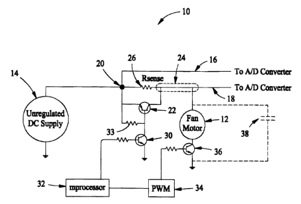
Figure 1 is a diagram of one embodiment of a closed-loop
motor control system 10. As explained in greater detail below, system 10
provides
closed loop motor control without using a Hall effect device or a voltage
regulator.
Rather, system 10 utilizes a plurality of switching elements and resistive
elements to
provide closed-loop motor control.
-3-
09HR19209
CA 02409586 2002-10-24
Control system 10 includes a fan motor 12 that operates in a
refrigerator (not shown in Figure 1 ), such as, for example, a condenser fan
motor or an
evaporator fan motor. Control system 10 is powered by an unregulated DC power
supply 14. Power supply 14 supplies power to other loads in addition to
control
system 10. Additionally, analog voltage signals from supply 14 are transmitted
via a
first line 16 to an analog-to-digital converter (ADC) (not shown). A second
line 18 is
also connected to the ADC.
Line 16 is electrically connected at a connection node 20 to a
switching element 22, e.g. a PNP transistor. PNP transistor 22 is also
electrically
connected to line 18 at a connection node 24 such that PNP transistor 22 is
between
lines 16 and 18 allowing for an opening and closing of current flow between
nodes 20
and 24 through transistor 22. For example, PNP transistor 22 emitter and
collector
terminals are connected to nodes 20 and 24 respectively. A resistive element
26, e.g.
a sense resistor in line 18, is connected to nodes 20 and 24 in parallel with
the emitter
and collector terminals of transistor 22. Fan motor 12 receives a load voltage
at node
24. A second switch 30 is connected between a base of transistor 22 and a
processor
32, e.g. a Hitachi model H8-3644 processor commercially available from
Hitachi,
Ltd., Tokyo, Japan. Processor 32 is operationally coupled to the ADC. In one
embodiment, switch 30 is a NPN transistor including a collector terminal
electrically
connected to a base terminal of PNP transistor 22. NPN transistor 30 further
includes
a base terminal electrically connected to processor 32. A resistor 33 connects
the base
of PNP transistor 22 to the emitter of PNP transistor 22. It should be
understood that
the present invention can be practiced with many alternative processors, and
is not
limited to practice in connection with just processor 32. Therefore, and as
used
herein, the term "processor" is not limited to just those integrated circuits
referred to
in the art as processors, but broadly refers to computers, processors,
microprocessors,
microcontrollers, microcomputers, application specific integrated circuits,
and other
programmable circuits including programmable logic controllers (PLCs).
Circuit 10 further includes a PWM control sub-circuit 34
connected to processor 32. In one embodiment, PWM control sub-circuit 34 is a
module within a Hitachi H8-3644 processor or other known microprocessor. PWM
circuit 34 is electrically connected to fan motor 12 via a transistor 36.
Although
control system 10 includes transistors including bipolar transistors, control
system 10
can utilize many alternative switching and current- or voltage-controlling
elements,
-4-
09HR19209
CA 02409586 2002-10-24
e.g. relays and Field Effect Transistors (FETs), such as, for example, Metal
Oxide
Semiconductor Field Effect Transistors (MOSFETs) and Junction FETs (JFETs).
In use, control system 10 performs closed-loop speed control
and diagnostic functions as directed by processor 32. To control the speed of
fan
motor 12, processor 32 bypasses sense resistor 26 by turning on PNP transistor
22.
Processor 32 measures the load voltage of motor 12 at node 24, and a duty
cycle for
PWM circuit 34 is set based on the load voltage measured at node 24.
For example, in an illustrative embodiment, it may be
appreciated that the power supply voltage is approximately equal to the sum of
V;~ at
node 24 and the applied voltage of PWM control sub-circuit 34. Thus, assuming
a
minimum power supply voltage of 12 volts, PWM sub-circuit voltage is
approximately V;" minus 12 volts. An appropriate duty cycle may be therefore
be
mathematically derived according to known theoretical or empirically
determined
relationships between an applied voltage signal from PWM control sub-circuit
34 and
motor voltage, motor voltage and A/D converter counts, and output voltage at
node 24
in relation to input voltage from power supply 14. For instance, in one
exemplary
embodiment, the duty cycle for PWM circuit 34 is governed by the following
relationship:
DutyCycle = 3 x 10⁻⁵ (Vin -12)4 - 0.0019(Yin -12)3 + 0.0433(Vin - I2)2
- 0.4198(Yin -12)+ 1.4591
In different embodiments, the duty cycle is calculated directly
by processor 32 according to such a relationship, or a pre-calculated duty
cycle value
corresponding to the sensed voltage is selected from a plurality of pre-
calculated
values associated with the processor, such as in a lookup table familiar to
those in the
art.
The above-described process is performed sequentially and
repeatedly while motor 12 is in an on state.
Processor 32 controls all devices receiving power from power
supply 14. To test the electrical functionality of fan motor 12, processor 32
switches
off all electrical loads on power supply 14. After all loads are shed from
power
supply 14, processor 32 switches PNP transistor 22 to an off state allowing a
measurable voltage drop across sense resistor 26 whenever current flows from
node
-5-
09HR19209
CA 02409586 2002-10-24
20 to node 24. PWM circuit 34 then energizes motor 12 using a duty cycle of
100
percent (PWM signal is kept high). Processor 32 then measures respective
analog
voltages from lines 16 and 18 and determines power consumption by sense
resistor
26, in accordance with the following relationship:
(Upper A l D Reading) - (Lower A l D Reading) 2
Rsense
where Upper AlD Reading is the supply voltage measured from line 16,
Lower AlD Reading is the motor load voltage measured from line 18, and Rsence
is a
resistance in ohms of sense resistor 26. Rsence, in one embodiment, is
selected to
produce current values of between about 1 mA and about 100 mA through resistor
26.
Processor 32 also provides for switching from motor functionality diagnosis to
closed
loop control. For example, after diagnosing that the motor functionality is
within a
predetermined operating range, i.e., that the motor is energized and not
locked,
processor 32 switches PNP transistor 22 to an on state and controls motor 12
as
explained above.
In a further embodiment, a filter 38 (shown in phantom in
Figure 1) is employed between motor 12 and ground to reduce undesirable
disturbances attributable to effects caused by the PWM wave form.
The above described motor speed control circuit provides for
constant fan speed control with diagnostic capabilities using an unregulated
power
supply. Through reduction in parts, compared to at least one known speed
sensor
system, an increase in reliability is facilitated. Also, as explained in
greater detail
below, using a fast frequency sweep over a slowly adjustable average frequency
in a
PWM controlled variable speed fan motor control system facilitates a reduction
in the
inherent motor and fixture resonances which can cause noise.
Figure 2 is a representation of a waveform 50 produced by a
conventional PWM circuit for a fifty percent duty cycle. Waveform 50 includes
a
plurality of individual waves 52. Each wave 52 includes a leading edge 54, a
high
portion 56, a trailing edge 58, and a low portion 60. Each wave 52 is
substantially
identical to each other wave 52.
-6-
09HR19209
CA 02409586 2002-10-24
During operation of a PWM controlled motor, the motor is
energized during high portions 56 and is not energized during low portions 60.
Since
each high portion 56 constitutes one-half of each wave 52, the motor is
operating at a
50% duty cycle. Typically, in a PWM controlled system, the duty cycle is
adjusted
based on various factors, such as, for example, a desired cooling rate. As a
result, the
motor may be modulated at one or more mechanical resonance frequencies causing
increased perceived noise to the consumer. For instance, a motor having a
mechanical
resonance frequency at a 50% duty cycle will resonate when controlled with
waveform 50 and produce more noise than when operated at a duty cycle not
corresponding to a mechanical resonance frequency.
Figure 3 is a representation of a monotonically increasing
waveform 70. Waveform 70 includes a first wave 72, a second wave 74, a third
wave
76, a fourth wave 78, a fifth wave 80, and a sixth wave 82. Each wave 70, 72,
74, 76,
78, 80, and 82 has a substantially similar period 84 and includes a leading
edge 86, a
high portion 88, a trailing edge 90, and a low portion 92. High portion 88 of
first
wave 72 is approximately 40% of period 84. High portion 88 of second wave 74
is
approximately 45% of period 84. High portion 88 of third wave 76 is
approximately
50% of period 84. High portion 88 of fourth wave 78 is approximately 55% of
period
84. High portion 88 of fifth wave 80 is approximately 60% of period 84. High
portion 88 of sixth wave 82 is approximately 40% of period 84. High portions
88
vary from 40% to 60% and average 50%, which is the duty cycle. Specifically,
high
portions 88 vary from a low value of approximately 10 percent below the
average
(50%) and monotonically increase to a high value of approximately 10 percent
above
the average forming a sweep action before returning to the low value and
sweeping
again. The average is the duty' cycle. In an alternative embodiment, the high
value is
approximately 20% above the average and the low value is approximately 20%
below
the average. In another embodiment, the high and low values are approximately
5%
above and below the average respectively. In yet another embodiment, the high
and
low values are more than 20% above and below the average respectively. In a
further
embodiment, the high and low values are less than 5% above and below the
average
respectively.
During operation of a PWM controlled motor (not shown in
Figure 3), the motor is energized during high portions 88 and not energized
during
low portions 92. Since an average of high portions 88 is 50%, the motor is
operating
_7_
09HR19209
CA 02409586 2002-10-24
at a 50% duty cycle. However, the sweep action distributes the excitation
energy over
a large frequency band i.e., a twenty- percent range from a 40% duty cycle to
a 60%
duty cycle. Accordingly, the resonance energy at any particular frequency is
lowered
and the resonant system has less time to build up an appreciable resonance and
associated noise. Because a motor has a large inertia compared to the fast
sweep rate,
the speed of a motor controlled with waveform 70 is substantially similar to
the speed
of a motor controlled with waveform 50 (shown in Figure 2). However, as
explained
above, waveform 70 distributes the excitation energy over multiple
frequencies,
facilitating a reduction in the occurrences of modulating the motor at a
resonance
frequency.
In one embodiment, processor 32 determines an average
speed and outputs a PWM waveform as is known in the art e.g. waveform 50. PWM
circuit 34 superimposes a plurality of sweep additions and subtractions while
maintaining the average set by processor 32. In another embodiment, processor
32
and PWM circuit 34 are integrated into a single chip (not shown). The single
chip
determines an average speed value and outputs a monotonically increasing
waveform
centered around the determined value. It is contemplated that the benefits of
distributing the excitation energy over multiple frequencies to facilitate a
reduction in
resonations accrue to systems and methods utilizing a monotonically decreasing
waveform centered around the average. For example, waveform 70 can be
reflected
about a horizontal axis and waves 72, 74, 76, 78, and 80 sent in reverse
order. The
motor is sent fifth wave 80 followed by fourth wave 78, third wave 76, second
wave
74, and finally first wave 72 before starting again with fifth wave 80.
Accordingly,
the motor receives a monotonically decreasing waveform while still maintaining
a
50% duty cycle.
Additionally, a random waveform centered around the
average will also distribute the excitation energy over multiple frequencies
and
facilitate a reduction in resonations. For example, sending waves 72, 74, 76,
78, and
80 randomly to a motor energizes the motor with a 50% duty cycle and
facilitates a
reduction in resonations by distributing the energy over different
frequencies. In one
embodiment, PWM circuit 34 includes a random number generator (not shown) and
utilizes the random number generator to generate random numbers between a
negative
limit and a positive limit with the same absolute value as the negative limit.
Each
random number is added to the average and thus the motor is regulated at a
duty cycle
_g_
09HR19209
CA 02409586 2002-10-24
set by processor 32 and a reduction in resonations is facilitated by
distributing the
excitation energy over multiple frequencies.
Figure 4 is a cross-sectional view of closed-loop PWM
controlled motor 12 (shown in Figure 1) including a housing 102, a stator
assembly
104, a rotor assembly 106, and a commutator assembly 108. Stator assembly 104
is
located within housing 102 and includes a stator core 110 including a stator
bore 112
for receiving rotor assembly 106. Stator core 110 further includes a plurality
of
wound field poles 114. Rotor assembly 106 includes rotor shaft 116 carrying
commutator assembly 108 and an armature core 118. Commutator assembly 108
includes a plurality of commutator bars 120 and a brush holder 122 including a
plurality of brushes (not shown). Commutator assembly 86 further includes a
plurality of insulator segments (not shown) arranged alternately with
commutator bars
120 in a circumferential direction of rotor shaft 116. In an alternative
embodiment,
motor 12 is an electronic DC motor and does not include commutator assembly
108.
Motor 12 is electrically connected to processor 32 and PWM control sub-circuit
34 as
shown in Figure 1.
During motor operation, processor 32 controls motor 12 as
explained above and outputs a PWM control signal. Additionally, PWM circuit 34
receives the PWM control signal and superimposes a plurality of sweep
additions and
subtractions to the PWM control signal while maintaining the average set by
processor 32. Accordingly, motor 12 is controlled with a closed loop motor
control
with out using a Hall effect device or a voltage regulator. Additionally, a
reduction in
resonance is facilitated by the superimposition of the sweep additions and
subtractions.
Figure 5 is a front view of a refrigerator 140 including a
housing 142, a freezer section 144, and a fresh food section 146. Refrigerator
140
further includes motor 12 (shown in Figure 4) mounted within housing 142.
Motor 12
is electrically connected to processor 32 and PWM control sub-circuit 34 as
shown in
Figure 1.
During operation of refrigerator 140, processor 32 controls
motor 12 as explained above and outputs a PWM control signal. Additionally,
PWM
circuit 34 receives the PWM control signal and superimposes a plurality of
sweep
additions and subtractions to the PWM control signal while maintaining the
average
-9-
09HR19209
CA 02409586 2002-10-24
set by processor 32. Accordingly, motor 12 is controlled with a closed loop
motor
control with out using a Hall effect device or a voltage regulator.
Additionally, a
reduction in resonance is facilitated by the superimposition of the sweep
additions and
subtractions. Accordingly, a. reduction of noise generated by refrigerator 140
is
facilitated.
While the invention has been described in terms of various
specific embodiments, those skilled in the art will recognize that the
invention can be
practiced with modification within the spirit and scope of the claims.
-10-