Note: Descriptions are shown in the official language in which they were submitted.
CA 02409780 2002-11-15
WO 02/075211 PCT/US02/05506
1
AZ-10
SEGMENTED RADIANT GAS BURNER
AND METHOD OF USE WITH GAS TURBINES
BACKGROUND OF THE INVENTION
This invention relates to a broadly modulated radiant gas
burner that yields minimal emissions of air-pollutants, espec-
ially nitrogen oxides (NOx). More particularly, the burner face
of this invention is a porous mat of metal and/or ceramic fibers
which is divided into segments that can be individually fired.
Radiant, surface-combustion gas burners are fed fuel gas
admixed with. enough air to ensure complete combustion of the fuel
gas. Because these burners function without secondary air, their
modulation of heat output is limited. Yet, there are important
uses of surface-combustion gas burners in tight spaces, such as
in the casings of gas turbines, where adding spare burners to
increase heat delivery is not a practical solution to broad
heating modulation.
Assignee's pending patent application No. 09/235,209, filed
January 22, 1999, discloses compact radiant gas burners that are
well suited for use with gas turbines. An important use of the
burner of this invention is with gas turbines.
A principal object of this invention is to provide compact
radiant gas burners featuring a broad range of heat delivery.
Another important object is provide such radiant gas burners
with internal walls that divide each burner into two or more
segments that can be individually and independently fired to vary
the thermal output.
Still another object is to provide segmented radiant gas
burners that are simple in construction as well as operation.
CA 02409780 2002-11-15
WO 02/075211 PCT/US02/05506
2
These and other features and advantages of the invention
will be apparent from the description which follows.
SUMMARY OF THE INVENTION
Basically, the segmented radiant gas burner of this
invention which has a combustion surface formed of metal and/or
ceramic fibers may have a unitary body with internal partitions
to provide independent burner segments, or it may have two or
more burner modules that are compactly fitted together.
U.S. Pat. No. 4,543,940 to Krill et al describes a segmented
radiant burner formed of large cylindrical segments that are
bolted together in axial alignment. This arrangement of large
burner segments was conceived to fit the peculiar shape of
combustion chambers of fire tube boilers. The serial alignment
involves sealing between the abutted ends of contiguous burner
sections and requires an individual duct to supply fuel gas and
air to each burner segment. The complex ducting of fuel gas and
air to each burner segment is antithetical to this invention's
objective of burner compactness that is essential to burners used
with gas turbines.
The combustion surface may be formed of ceramic fibers as
taught by U.S. Pat. No. 4,746,287 to Lannutti, of metal fibers as
set forth in U.S. Pat. No. 4,597,734 to McCausland, or of mixed
metal and ceramic fibers according to U.S. Pat. No. 5,326,631 to
Carswell et al. For high surface firing rates, say, at least
about 500,000 BTU/hr/sf (British.Thermal Units per hour per
square foot) of burner face, a rigid but porous mat of sintered
metal fibers with interspersed bands or areas of perforations is
preferred. Such a burner face is shown in FIG.1 of U.S. Pat. No.
5,439,372 to Duret et al. Still another form of porous metal
fiber mat sold by N.V. Acotech S.A. of Zwevegem, Belgium, is a
CA 02409780 2002-11-15
WO 02/075211 PCT/US02/05506
3
knitted fabric made with a yarn formed of metal fibers. In the
rigid porous and perforated burner of Duret etal, radiant surface
combustion is interspersed with blue flame combustion from the
perforations. Similarly, the yarn of the knitted metal fiber
fabric provides radiant surface combustion and the interstices of
the knitted fabric naturally provide interspersed spots of
increased porosity that yield blue flames.
At the aforesaid high surface firing rates, the flames from
the areas of increased porosity produce such intense non-surface
radiation that the normal surface radiation from the areas of
lower porosity disappears. However, the dual porosities make it
possible to maintain surface-stabilized combustion, i.e., surface
combustion stabilizing blue flames attached to the burner face.
Burner faces with dual porosities will be referred to as surface-
stabilized burners for brevity. With such burners, flaming is so
compact that visually a zone of strong infrared radiation appears
suspended close to the burner face. It is noteworthy that with
at least about 40o excess air, surface-stabilized combustion
yields combustion products containing as little as 2 ppm (parts
per million) NOx and not more than 10 ppm CO and UHC (unburned
hydrocarbons), combined.
Inasmuch as the segmented burner of this invention is
particularly valuable in uses where the combustion zone is
spatially limited, it is seldom a flat burner. Cylindrical
burner faces and variations thereof, e.g., tapered or conical,
are the usual forms of the segmented burner.
The burner segments which fit together may be designed to
deliver equal quantities of heat, but it is usually advantageous
to have segments of unequal heat delivery capacities. For
example, a two-segment burner, can have one segment with 60o and
CA 02409780 2002-11-15
WO 02/075211 PCT/US02/05506
4
the other segment with 400 of the total heat delivery capacity of
the burner. Such unequal segments permit greater heat delivery
modulation than if the burner had two equal segments. The same
is true of three-segment burners. Three segments of 55%, 35% and
10% of heat delivery capacity permit greater modulation of heat
delivery than is possible with three segments of equal heat
delivery capacity.
BRIEF DESCRIPTION OF THE DRAWINGS
To facilitate further description and understanding of the
invention, reference will be made to the accompanying drawings of
which:
FIG.1 is a schematic representation of a simple two-segment
cylindrical burner shown in axial section;
FIG.2 is a similar representation of a three-segment
cylindrical burner shown in axial section;
FIG.3 is a left end view of the burner of FIG.2;
FIG.4 is a left end view of the burner of FIG.1 modified to
provide three burner segments;
FIG S schematically represents a hemispherical burner having
two burner segments;
FIG.6 is a schematic axial section of a three-segment
conical burner adapted for use with a gas turbine; and
FIG.7 shows an alternate form of an element of the burner of
FIG.6.
DESCRIPTION OF PREFERRED EMBODIMENTS
FIG.l schematically depicts a two-segment cylindrical burner
having a porous fiber combustion surface 11 which is divided
into two separate burning segments by a funnel-like baffle 12.
Tube 13 connected to frusto-conical portion 14 of funnel 12 is
fitted co-axially in cylinder 15 to create core plenum 16 and
CA 02409780 2002-11-15
WO 02/075211 PCT/US02/05506
annular plenum 17. Core plenum 16 expands beyond tapered baffle
14 into plenum 18 which supplies fuel gas and air to segment A of
combustion surface 11. Segment A of surface 11 is the portion to
the right of the line where baffle 14 meets the inner support
screen (not shown) of fiber surface 11. Porous fiber combustion
surface 11 surrounding annular plenum 17 is segment B contiguous
to segment A.
It is obvious that fuel gas and air can be supplied to tube
l3 for surface combustion on only segment A of porous fiber layer
11. For increased thermal output, fuel gas and air can be
introduced via cylinder 15 to annular plenum 17 for combustion on
segment B of fiber layer 11. Of course, the reverse order of
firing can be carried by feeding fuel gas and air to plenum 17
and feeding fuel. gas and air to core plenum 16 when increased
heat output is desired.
The simplicity and compactness of burner 10 of FIG.1
demonstrates that it can be made with a unitary cylindrical body
having a hemispherical closed end and a funnel-like baffle
inserted through the opposite open end of the cylindrical body.
In fact, that is the construction that has been described in
relation to FIG. 1. However, if~each of lines 13, 14 in FIG.1,
which form funnel 12, are considered~as two contiguous metal
sheets and segments A, B of fiber layer 11 are not united at
circumferential line S, burner 10 becomes one having two
telescoped burner modules. The module with plenum .16, 18 has its
tube 13 inserted into a central, similar tube of annular plenum
17. The insertion is made from the right end of cylinder l5 that
supports segment B of porous fiber layer 11. When tapered wall
14 of plenum 18 is brought into contact with similar tapered wall
of annular plenum 17, the insertion is completed and segment A of
CA 02409780 2002-11-15
WO 02/075211 PCT/US02/05506
6
combustion surface 11 meets segment B to function essentially as
if surface 11 had been vacuum molded as a continuous porous fiber
layer 11 spanning both plenums 17, 18.
FIG.2 shows an axial section of cylindrical burner 20 that
is sealed by metal disk 21 at its right end and open at its
opposite end.
FIG.3 is a left end view of burner 20 revealing three radial
baffles 22, 23, 24 which form three plenums 25, 26, 27 in burner
20. Plenums 25, 26, 27 feed three equal segments of porous fiber
combustion surface 28 on cylinder 29. However, it is usually
preferable to make the angles between baffles 22, 23, 24 unequal
so that the areas of the three segments of combustion surface 28
are also unequal. Moreover, baffles need not be radial. For
example, two baffles at right angles to each other within
cylinder 29 can provide three plenums of unequal size. A single
baffle that is not,a diametrical divider will form two plenums of
unequal size in burner 20 with porous fiber layer 28 divided into
two segments of unequal areas.
FIG.4, like FIG.3, is an open end view of a cylindrical
burner 30 that, like burner 10 of FIG. l, has a funnel-like plenum
surrounded by an annular plenum. Burner 30 differs from burner
in that the annular plenum.is divided into two unequal parts
by baffles 31, 32 extending from tube 33 outwardly to the
cylindrical screen (not shown) that supports porous fiber layer
34. Thus, baffles 31, 32 have converted the two-segment burner
10 of FIG.1 into three-segment burner 30.
FIG.5 is a diametrical sectional view of hemispherical
burner 40 that has a pan plenum 41 with inlet opening 42. A
hemispherical screen which supports a porous layer 43 of metal
and/or ceramic fibers is attached to pan 41. Funnel-like baffle
CA 02409780 2002-11-15
WO 02/075211 PCT/US02/05506
7
44 with its~tube 45 extending through pan 41 divides combustion
surface 43 into two segments, A, B that can be fired separately
or together. Fuel gas and air supplied to tube 45 will yield
radiant surface combustion on segment A of porous fiber layer 43.
When increased heating is desired, fuel gas and air introduced
through inlet 42 to pan 41 will combust on segment B of porous
fiber layer 43. Of course, combustion can be carried out with
only segment B of burner 40. When greater heating is desired,
fuel gas and air can be fed to tube 45 for combustion on segment
A of porous fiber layer 43.
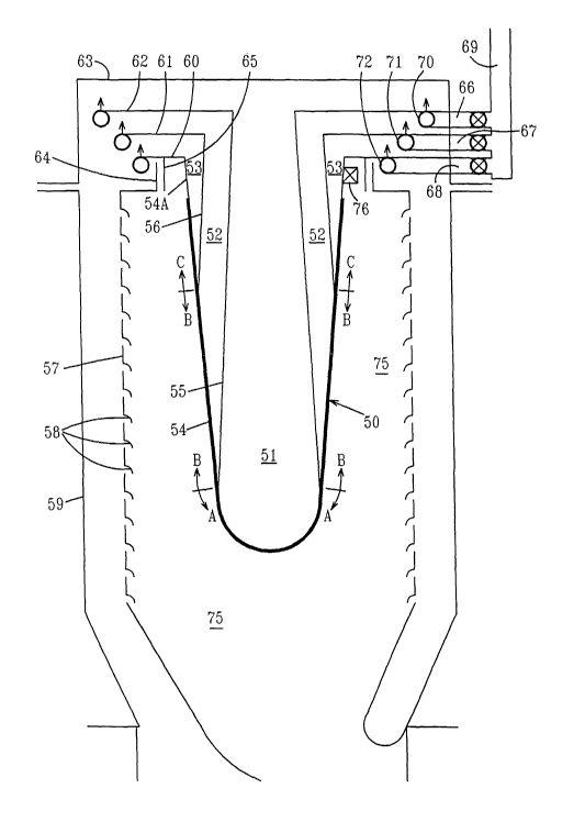
FIG.6 demonstrates a three-segment burner 50 of the
invention adapted for use with a gas turbine. FIG.6 is presented
as an improved (provides greater thermal modulation) burner for
replacement of burner 62 in FIG.6 of assignee's application No.
09/235,209. Whereas prior burner 62 has a single plenum 63, new
burner 50 has three plenums, 51, 52, 53 which supply fuel gas and
air to three segments A, B, C of porous combustion surface 54.
Tubular baffle 55 separates plenum 51 from plenum 52 which is
separated from plenum 53 by tubular baffle 56. Burner 50 of this
invention, like burner 62 of assignee's prior application, is
surrounded by metal liner 57 that has multiple louvers 58. Liner
57 spaced from combustion surface 54 serves to confine the
combustion zone.
Housing 59 is a steel cylinder attached to the casing of a
gas turbine (not shown). Three-segment burner 50 is attached to
housing cap 63 by spacer bolts (not shown). Inasmuch as prior
burner 62 was made with a dual porosity burner face 64, the new
three-segment burner 50 can also have burner face 54 with dual
porosity. The tapered cylindrical support of burner face 54 has
an impervious cylindrical extension 54A welded to a circular
CA 02409780 2002-11-15
WO 02/075211 PCT/US02/05506
8
opening in metal disk 60. Similarly, baffle 56 is welded to an
opening in disk 61 and baffle 55 is connected to an opening in
disk 62. Spacer bolts (not shown) hold disks 60, 61, 62 in the
desired spaced arrangement and spacer bolts between disk 62 and
housing cap 63 support the entire assembly of disks 60, 61, 62
which are components of burner 50. Cylindrical band 65 is welded
to disk 60 and is dimensioned for a slip-fit with collar 64 of
liner 57. Thus, when cap 63 is lifted away from housing 59, all
of burner 50 is withdrawn from housing 59.
Plenums 51, 52, 53 are each supplied with fuel gas by valued
tubes 66, 67, 68, respectively. Pipe 69 feeds tubes 66, 67, 68
which are connected touring manifolds 70, 71, 72, respectively,
each manifold having multiple holes positioned to inject fuel gas
above disks 62, 61, 60, respectively. Compressed air from the
compressor section of a gas turbine (not shown) flows into and
fills housing 59 which is part of the casing of the turbine.
Compressed air in housing 59 flows over disks 60, 61, 62 and into
plenums 53, 52, 51, respectively. Compressed air discharges from
plenums 51, 52, 53 through segments A, B, C, respectively, of
porous fiber burner face 54 into combustion zone 75. Compressed
air also passes through the multiple louvers 58 of liner 57 into
combustion zone 75. By opening the valve of tube 68, fuel gas is
injected upward as multiple jets from holes in ring manifold 72
into the compressed air flowing over disk 60 and the resulting
gas-air mixture flows into plenum 53 from which it exits through
segment C of porous burner face 54 and, upon ignition, undergoes
radiant surface combustion. Any known igniter 76 positioned
below disk 60 near segment C will ignite the gas-air mixture
exiting segment C of porous burner face 54.
When greater thermal delivery is required, fuel gas may
CA 02409780 2002-11-15
WO 02/075211 PCT/US02/05506
9
similarly be fed through valued tube 67 to ring manifold 71, and
injected by manifold 71 as multiple jets into compressed air
flowing between disks 61, 62.. Thence, the mixture flows through
plenum 52 and segment B of burner face 54 to produce more
surface-stabilized combustion. For maximum heating, fuel gas is
admitted through valued tube 66 to manifold 70 from which it
escapes as multiple jets into compressed air passing between
disks 62 and housing cap 63. The gas-air mixture fills plenum 51
and combusts upon exiting segment A of porous burner face 54.
The products of combustion from segments A, B, C mix with
compressed air entering combustion zone 75 through louvers 58 of
liner 57. The total hot gases flow from combustion zone 75
through curved duct 77 (partially shown) which channels the hot
gases to the turbine (not shown) as the driving force thereof.
The great range of thermal modulation made possible by the
invention is best appreciated if the area of combustion surface
54 of segmented burner 50 and the area of combustion surface 64
of prior burner 62 (application No. 09/235,209) are made equal.
Burner 62 can be thermally modulated over a range that is
characteristic for the selected type of combustion surface. If
the same type of combustion surface is used on segmented burner
50, then all three segments A, B, C can be individually and
independently modulated to the same extent as combustion surface
64 of prior burner 62. But segmented burner 50 can have any one
or two of segments A, B, C turned off by closing valued tubes 66,
67, 68, respectively, to achieve a great turn-down of heat output
to a small fraction. of the lowest turn-down possible with prior
burner 62.
A two-segment burner that still permits substantially
broader thermal modulation than prior burner 62 can be visualized
CA 02409780 2002-11-15
WO 02/075211 PCT/US02/05506
by eliminating either tubular baffle 55 along with disk 62, ring
manifold 70 and valued tube 66, or tubular baffle 56 along with
disk 61, manifold 71 and valued tube 67. Segmented burner 50 is
shown in FIG.6 in a preferred cone-like shape, i.e., a conical
form with a convex end in lieu of a pointed apex. This term,
cone-like shape, as herein used, shall also include truncated
conical forms. Of course, other forms of segmented burners, such
as those shown in FIGS.1, 2, 4, 5 may be adapted for use with gas
turbines.
The unique feature of segmented burners of this invention
for gas turbines is that compressed air from the compressor of a
gas turbine flows into and around the segmented burner
continuously whether one or all the segments are being fed fuel
gas. The percentage of compressed air going into each segment
and around the burner being fixed by the dimensions given the
various parts of the burner. For example, if the space between
disks 61, 62 is reduced, less compressed air will flow into
plenum 52. In short, while a burner is in operation, the flow of
compressed air into any plenum cannot be varied. Only the flow
of fuel gas can be varied to each plenum.
While burner 50 is shown in FIG.6 with a louvered liner 57,
an alternate liner is known as a backside-cooled liner (ASME
Paper 99 - GT-239). Fig.7 is a schematic representation of
backside-cooled liner 57A as a substitute for louvered liner 57
of FIG.6. FIG.7 shows only the right profile of liner 57A
inasmuch as the left profile is only a mirror image of FIG.7.
Liner 57A is without louvers or other openings except for a few
louvers 58A in the end portion of liner 57A which is connected to
curved duct 77. A cylindrical metal shell 57B, called convector
in the ASME Paper, surrounds liner 57A and is spaced therefrom to
CA 02409780 2002-11-15
WO 02/075211 PCT/US02/05506
11
provide a narrow annular gap. Convector 57B extends over
substantially the full length of liner 57A and is connected and
sealed to liner 57A at 57C where liner 57A meets curved duct 77.
Thus, compressed air flowing between housing 59 and
convector 57B will, besides entering the spaces between disks 60,
61, 62 and housing cap 63, flow through the gap between convector
57B and liner 57A exiting through a few rows of openings or
louvers 58A in the portion of liner 57A adjacent to curved duct
77. Accordingly, any liner that serves to confine the combustion
zone close to the burner surface and to moderate the combustion.
temperature can be used with the segmented burner.
Moreover, each burner need not have an individual liner.
Application No. 09/235,209 shows a circular array of five burners
in FIG.3 which have a pair of metal liners that confine the
combustion of all five burners in an annular zone. Such a
collective liner may be used for several burners of this
invention. Inasmuch as the collective liner is in two concentric
parts, it is possible to cool each part with compressed air in a
different way. For example, the inner liner may be louvered and
the outer liner may be backside-cooled, or vice versa.
As known, the metal screen which supports the porous fiber
layer of surface combustion burners usually has a perforated
back-up plate that helps to ensure uniform flow of the fuel gas-
air mixture though all of the porous fiber burner face. In a
unitary (not modular) segmented burner of this invention, each
internal baffle can be held in place by welding to a back-up
plate. In the absence of a back-up plate, a baffle can be welded
to the screen that supports the porous fiber layer.
While natural gas is a fuel commonly used with gas turbines,
the burner of this invention may be fired with higher
CA 02409780 2002-11-15
WO 02/075211 PCT/US02/05506
12
hydrocarbons, such as propane. Liquid fuels, such as alcohols
and gasoline, may be used with the burner of the invention, if
the liquid fuel is completely vaporized before it passes through
the porous burner face. The term, gaseous fuel, has been used to
include fuels that are normally gases as well as those that are
liquid but completely vaporized prior to passage through the
burner face. Another feature of the invention is that the burner
is effective even with low BTU gases, such as landfill gas that
often is only about 40% methane.
The term, excess air, has been used herein in its
conventional way to mean the amount of air that is in excess of
the stoichiometric requirement of the fuel with which it is
mixed.
Those skilled in the art will visualize variations and
modifications of the invention in light of the foregoing
teachings without departing from the spirit or scope of the
invention. For example, circular manifold 70 in FIG.6 can be
eliminated if valued fuel tube 66 is extended so that it
discharges through a mixing nozzle into the opening where baffle
55 is joined to disk 62. Accordingly, only such limitations
should be imposed on the invention as are set forth in the
appended claims.