Language selection

Search

Patent 2409972 Summary

Third-party information liability

Some of the information on this Web page has been provided by external sources. The Government of Canada is not responsible for the accuracy, reliability or currency of the information supplied by external sources. Users wishing to rely upon this information should consult directly with the source of the information. Content provided by external sources is not subject to official languages, privacy and accessibility requirements.

Claims and Abstract availability

Any discrepancies in the text and image of the Claims and Abstract are due to differing posting times. Text of the Claims and Abstract are posted:

  • At the time the application is open to public inspection;
  • At the time of issue of the patent (grant).
(12) Patent: (11) CA 2409972
(54) English Title: FIXED GUIDE VANE ASSEMBLY SEPARATED INTO SECTORS FOR A TURBOMACHINE COMPRESSOR
(54) French Title: DISTRIBUTEUR FIXE SEPARE EN SECTEURS POUR COMPRESSEUR DE TURBOMACHINE
Status: Term Expired - Post Grant Beyond Limit
Bibliographic Data
(51) International Patent Classification (IPC):
  • F01D 09/00 (2006.01)
  • F01D 09/04 (2006.01)
  • F01D 25/24 (2006.01)
  • F04D 29/54 (2006.01)
(72) Inventors :
  • BERTRAND, JEAN-LOUIS (France)
  • PERROLLAZ, JEAN-MARC CLAUDE (France)
(73) Owners :
  • SNECMA
(71) Applicants :
  • SNECMA (France)
(74) Agent: LAVERY, DE BILLY, LLP
(74) Associate agent:
(45) Issued: 2011-04-12
(22) Filed Date: 2002-10-28
(41) Open to Public Inspection: 2003-04-30
Examination requested: 2007-08-24
Availability of licence: N/A
Dedicated to the Public: N/A
(25) Language of filing: English

Patent Cooperation Treaty (PCT): No

(30) Application Priority Data:
Application No. Country/Territory Date
01 14102 (France) 2001-10-31

Abstracts

English Abstract


The invention relates to a fixed guide vane
assembly comprising a circular casing composed of at
least two parts (11) and supporting sectors (5), each
composed of an inner segment (7) and an outer segment
(6) connected by vanes (8). The parts of the casing
and the sectors of the guide vane assembly are held
together by a system forming a slide and a slider.
Anti-rotation means (30) are provided to prevent the
sectors from rotating with respect to the casing.


French Abstract

L'invention porte sur un ensemble d'aube directrice fixe comprenant un carter circulaire composé d'au moins deux parties (11) et des secteurs de soutien (5), chacun composé d'un segment interne (7) et d'un segment externe (6) raccordés par des aubes (8). Les parties du carter et les secteurs de l'ensemble d'aube directrice sont retenus ensemble par un système formant une coulisse et d'une pièce coulissante. Un dispositif anti-rotation (30) est fourni pour empêcher les secteurs de tourner autour du carter.

Claims

Note: Claims are shown in the official language in which they were submitted.

8
CLAIMS
What is claimed is:
1. A vane assembly for a compressor, comprising:
sectors each having an inner segment and an outer
segment connected by vanes;
a casing configured to support the sectors in
contact with each other; and
an anti-rotation lock between two adjacent sectors
and configured to prevent said sectors supported by the
casing from rotating;
wherein said anti-rotation lock has an edge
configured to fit into a groove of said casing and a pin
on said edge configured to fit into a notch in said
casing.
2. A vane assembly according to claim 1, wherein
said sectors and said anti-rotation lock are in a shape
of an arc of a circle.
3. A vane assembly according to claim 1, wherein
the casing is composed of two parts.
4. A vane assembly according to claim 3, wherein
said two parts are in a form of a semi-circle.
5. A vane assembly according to claim 3, wherein
said two parts are in contact with each other.

9
6. A vane assembly according to claim 5, wherein
said two parts are fixed to each other at joint planes.
7. A vane assembly according to claim 1, wherein
the casing comprises two radial sides facing each other.
8. A vane assembly according to claim 1, wherein
said casing is circular.
9. A vane assembly according to claim 1, wherein
said edge is an outer edge of said anti-rotation lock.
10. A vane assembly according to claim 1, wherein
said edge is an inner edge of said anti-rotation lock.
11. A vane assembly according to claim 1, wherein
said anti-rotation lock comprises an inner edge and an
outer edge, each edge being configured to fit into a
groove of said casing.
12. A vane assembly according to claim 11, wherein
each of said inner and outer edges has a pin configured
to fit into a notch in said casing.
13. A vane assembly according to claim 1, wherein
said groove has a height that enables passage of said
edge with said pin.

Description

Note: Descriptions are shown in the official language in which they were submitted.


CA 02409972 2002-10-28
1
FIXED GUIDE VANE ASSEMBLY SEPARATED INTO SECTORS FC>R A
TURBOMACHINE COMPRESSOR
DESCRIPTION
Technical domain
The invention presented herein concerns the high
pressure turbine of a turbomachine such as a turbojet
used on an aircraft. More precisely, it concerns a
fixed guide vane assembly separated into sectors for a
turbomachine compressor.
State of prior art
There is a very large variety of compressors for
turbomachines. Manufacturers efforts are being made to
improve performances, and also to improve
manufacturing, reduce costs and ease of maintenance..
One known improvement consisted of separating the
fixed guide vane assembly of the compressor for a
turbomachine into sectors. Patent US-A-4 126 405
divulges a segmented assembly of a turbine distributor.
Document FR-A-2 728 015 divulges a turbine stator
distributor comprising sectors each composed of an
inner segment and an outer segment connected together
by vanes. A casing built into the compressor stator
will support the sectors placed in contact with each
other. Anti-rotation means are provided to prevent
rotation of the sectors supported by the casing.
Presentation of the invention
This invention was designed to further improve
manufacturing and the cost of a fixed guide vane
SP 19260 JL

CA 02409972 2002-10-28
2
assembly for a turbo-machine compressor. This is done
by making the casing in two or more parts, to
facilitate manufacturing. The parts of the casing and
the guide vane assembly sectors are held together ~y a
slide and slider system. Means of preventing rotation
are provided to prevent the sectors from rotating with
respect to the casing.
Therefore, the purpose of the invention is a fixed
sectorized guide vane assembly for a compressor :gin a
turbo-machine comprising:
- sectors in the shape of an arc of a circle each
composed of an inner segment and an outer
segment connected by vanes,
- a circular casing integrated into the compressor
stator, that will support the sectors in contact
with each other,
- anti-rotation means designed to prevent sectors
supported by the casing from rotating,
characterized in that:
- the casing is composed of at least two parts, in
contact with each other and fixed to each other
at joint planes and including means forming a
slide,
the sectors form slider means adapted to the
means forming a slide in the parts of the
casing,
- and anti-rotation means comprise anti-rotation
means fixed to the joint planes of the parts of
the casing by attachment means, and anti-
rotation means blocked on the parts of the
SP 19260 JL

CA 02409972 2002-10-28
3
casing by locking means at the contact between
the sectors.
Preferably, the casing is composed of two parts in
the form of a semi-circle.
According to one preferred variant embodiment, the
casing comprises two radial sides facing each other,
the means forming a slide comprise two opposite grooves
formed in the sides, the edges of the outside segments
of the sectors forming means forming a slide.
The anti-rotation means fixed to the joint planes
may then comprise at least one strip held immobile
between the two grooves by the said attachment means
and forming a stop for a sector sliding in a slide in a
casing. This strip may be a two-arm clip inserted by
bringing the two arms towards each other in the
reception housings provided in the grooves, and fixed
in place in these housings by releasing the two arms,
thus forming the said attachment means. The anti-
rotation means fixed to the joint planes may also
comprise at least one anti-rotation lock composed of an
element comprising means forming a slider adapted to
the means forming a slide in the parts of 1=he casing,
the element also comprising immobilization means on the
casing. These immobilization means may be of mortise
and tenon type, with a tenon engaging in the mortise
when the element is pushed in a direction perpendicular
to the direction in which the element slides in the
casing, thus forming the said attachment means. One of
the ends of the outer segment of the sector adjacent to
the said element may have a clearance such that the
element can be pushed into the said perpendicular
SP 19260 JL

CA 02409972 2002-10-28
4
direction when this adjacent sector is slid to come
into contact with the said element.
The anti-rotation means blocked on the part: of
the casing may then comprise at least one anti-rotation
lock formed of an element comprising means forming a
slider adapted to the said means forming a slide in the
parts of the casing, the element also comprising
immobilization means on the casing. These
immobilization means may be of the mortise and tenon
type, the tenon fitting into the mortise when the
element is pushed in a direction perpendicular to the
direction in which the element slides in the casing,
thus forming the said blocking means. One of the ends
of the outer segment of a sector adjacent to the said
element have a clearance such that the element can be
pushed in the said perpendicular direction, when this
adjacent sector is slid to come into contact with the
said element.
Brief description of the drawings
The invention will be better understood and other
advantages and special features will become clear after
reading the following description given as a :non
limitative example, accompanied by the atta~~hed
drawings among which:
- figure 1 is a partial sectional view of a tu:rbo-
machine compressor using a fixed sector.ized
guide vane assembly according to the invention,
- figure 2 is a partial oblique view of a faxed
sectorized guide vane assembly according to the
invention,
SP 19260 JL

CA 02409972 2002-10-28
figure 3 is an oblique view of an anti-rotaJ_ion
lock for the joint plane of part of a casing for
the fixed sectorized guide vane assembly
according to the invention,
5 - figure 4 is an oblique view of an anti-rota~ion
lock placed between two sectors of a faxed
sectorized guide vane assembly according to the
invention,
- figures 5 and 6 illustrate two steps in the
placement of an anti-rotation lock between two
sectors of a fixed sectorized guide vane
assembly according to the invention.
Detailed description of embodiments of the invention
Figure 1 is a partial sectional view of the
compressor of a turbomachine using fixed sector:ized
guide vane assemblies l, 2 and 3 according to the
invention. These guide vane assemblies are
functionally identical.
We will describe guide vane assembly 1 rnore
precisely. It comprises a circular casing 4 integrated
into the compressor stator and supporting sectors such
as sector 5.
A sector 5 is composed of an inner segment 7 and
an outer segment 6 connected to each other by vanes 8.
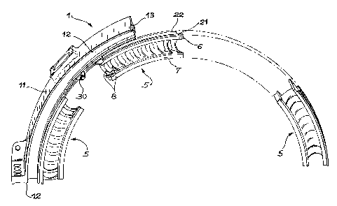
Figure 2 is a partial and exploded view of the
sectorized fixed guide vane assembly 1. For example,
it comprises a casing in two parts in the form of a
semi-circle. Figure 2 shows a partial view of one of
the parts 11 of this casing with one of its joint
planes 12 that will be fixed on the corresponding joint
SP 19260 JL

CA 02409972 2002-10-28
6
plane of the other part of the casing. Three sectors 5
currently being assembled are represented. For a
sector 5, the outer segment 6, the inner segment 7 and
the connecting vanes 8 can be recognized.
The part of the casing 11 comprises two radial
sides 12 and 13 facing each other and each provided
with a groove. The grooves are facing each other to
form a slide. The edges 21 and 22 of the outer segment
6 of the sector 5 project outwards to act as a slider
free to slide in the slide formed by the part of casing
11.
Before engaging a first sector 5 onto the part of
the casing 11, an anti-rotation lock is installed on
the joint plane 12 of the part of the casing 11. This
may be a strip or lock such as that shown in figure 4.
Figure 2 also shows an anti-rotation lock 30
placed
between
two
sectors
5.
This
lock
30
is
shown
in
an oblique view in figure 3. It is formed of an
element
31
placed
between
the
two
sides
12
and
13
of
the part of the casing 11 (see figure 2). 'rhe element
31 is in the shape of an arc of a circle and is
continued
by
an
outer
edge
32
and
an
inner
edge
33.
The edges 32 and 33 are designed such that the locls
30
can slide in the grooves of the part of the casing 11.
The outer edge 32 comprises a pin 34 projecting from
the plane of the element 31. The same is applicable
for the pin 35 on the inner edge 33.
Figures 5 and 6 illustrate two steps in the
placement
of
an
anti-rotation
lock
between
two
30 sectors
5.
A
single
one
of
the
sides
of
the
part.
of
the casing 11 has been shown to facilitate
SP 19260 JL

CA 02409972 2002-10-28
7
understanding. The groove 14 provided in this side can
be seen.
Figure 5 shows a first sector 5 already installed
(at the left of the figure) and a second sector .'i in
the process of being installed (at the right of the
figure). A lock 30 was inserted between these two
sectors by sliding. It will be noted that the height
of the groove 14 enables the passage of the outer edge
of lock 30 with its pin 34.
The element 30 slides until it comes into contact
with the first sector 5. For element 30, this
corresponds to a relative position with respect to the
part of the casing 11 such that the pin 34 is facing a
notch 15 machined in the part of the casing 11. All
that is necessary then is to push upwards on the lock
30 (for the view shown in figures 5 and 6) so that the
pin 34 can penetrate into the notch 15, and the lock 30
then stays in the raised position.
The second sector 5 may then be pushed towards the
lock 30. This second sector 5 has a clearance 23 at
the end in contact with the lock 30, such that pari~ of
the outer segment 6 passes under the lock 30.
The anti-rotation lock 40 at the joint plane szown
in figure 4 is installed in the same way as the lock in
figure 3. It is formed of an element 41 that is pl,~ced
between the two sides of the part of the casing. The
element 41 is continued by an outer edge 42 and. an
inner edge 43. The outer edge 42 comprises a pin 44
projecting from the plane of the element 41. The name
is true for the pin 45 on the inner edge 43.
SP 19260 JL

Representative Drawing
A single figure which represents the drawing illustrating the invention.
Administrative Status

2024-08-01:As part of the Next Generation Patents (NGP) transition, the Canadian Patents Database (CPD) now contains a more detailed Event History, which replicates the Event Log of our new back-office solution.

Please note that "Inactive:" events refers to events no longer in use in our new back-office solution.

For a clearer understanding of the status of the application/patent presented on this page, the site Disclaimer , as well as the definitions for Patent , Event History , Maintenance Fee  and Payment History  should be consulted.

Event History

Description Date
Inactive: Expired (new Act pat) 2022-10-28
Common Representative Appointed 2019-10-30
Appointment of Agent Request 2018-09-14
Revocation of Agent Request 2018-09-14
Inactive: Agents merged 2018-09-01
Inactive: Agents merged 2018-08-30
Grant by Issuance 2011-04-12
Inactive: Cover page published 2011-04-11
Pre-grant 2011-01-21
Inactive: Final fee received 2011-01-21
Notice of Allowance is Issued 2010-09-14
Letter Sent 2010-09-14
Notice of Allowance is Issued 2010-09-14
Inactive: Approved for allowance (AFA) 2010-09-10
Amendment Received - Voluntary Amendment 2010-05-19
Inactive: S.30(2) Rules - Examiner requisition 2009-11-23
Amendment Received - Voluntary Amendment 2009-07-22
Inactive: S.30(2) Rules - Examiner requisition 2009-01-22
Letter Sent 2008-02-22
Letter Sent 2007-09-14
Request for Examination Received 2007-08-24
Request for Examination Requirements Determined Compliant 2007-08-24
All Requirements for Examination Determined Compliant 2007-08-24
Inactive: IPC from MCD 2006-03-12
Application Published (Open to Public Inspection) 2003-04-30
Inactive: Cover page published 2003-04-29
Inactive: First IPC assigned 2003-01-10
Inactive: Filing certificate - No RFE (English) 2002-12-17
Letter Sent 2002-12-17
Application Received - Regular National 2002-12-17

Abandonment History

There is no abandonment history.

Maintenance Fee

The last payment was received on 2010-09-24

Note : If the full payment has not been received on or before the date indicated, a further fee may be required which may be one of the following

  • the reinstatement fee;
  • the late payment fee; or
  • additional fee to reverse deemed expiry.

Patent fees are adjusted on the 1st of January every year. The amounts above are the current amounts if received by December 31 of the current year.
Please refer to the CIPO Patent Fees web page to see all current fee amounts.

Owners on Record

Note: Records showing the ownership history in alphabetical order.

Current Owners on Record
SNECMA
Past Owners on Record
JEAN-LOUIS BERTRAND
JEAN-MARC CLAUDE PERROLLAZ
Past Owners that do not appear in the "Owners on Record" listing will appear in other documentation within the application.
Documents

To view selected files, please enter reCAPTCHA code :


To view images, click a link in the Document Description column (Temporarily unavailable). To download the documents, select one or more checkboxes in the first column and then click the "Download Selected in PDF format (Zip Archive)" or the "Download Selected as Single PDF" button.

List of published and non-published patent-specific documents on the CPD .

If you have any difficulty accessing content, you can call the Client Service Centre at 1-866-997-1936 or send them an e-mail at CIPO Client Service Centre.

({010=All Documents, 020=As Filed, 030=As Open to Public Inspection, 040=At Issuance, 050=Examination, 060=Incoming Correspondence, 070=Miscellaneous, 080=Outgoing Correspondence, 090=Payment})


Document
Description 
Date
(yyyy-mm-dd) 
Number of pages   Size of Image (KB) 
Description 2002-10-27 7 274
Abstract 2002-10-27 1 19
Claims 2002-10-27 4 121
Drawings 2002-10-27 4 125
Representative drawing 2003-01-12 1 15
Claims 2009-07-21 8 249
Abstract 2009-07-21 1 17
Claims 2010-05-18 2 55
Courtesy - Certificate of registration (related document(s)) 2002-12-16 1 106
Filing Certificate (English) 2002-12-16 1 159
Reminder of maintenance fee due 2004-06-28 1 111
Reminder - Request for Examination 2007-07-02 1 118
Acknowledgement of Request for Examination 2007-09-13 1 189
Commissioner's Notice - Application Found Allowable 2010-09-13 1 166
Fees 2004-09-23 1 37
Fees 2005-09-22 1 34
Fees 2006-09-24 1 48
Fees 2007-09-19 1 45
Fees 2008-09-28 1 46
Correspondence 2011-01-20 1 37