Note: Descriptions are shown in the official language in which they were submitted.
CA 02410127 2002-10-29
JJ-11 847CA
TITLE: PIPING JOINT STRUCTURE
FIELD OF THE INVENTION
The present invention relates to a piping joint
structure in which a male member can be detachably
connected to a female member.
BACKGROUND OF THE INVENTION
As a piping joint structure, there have been
known, for example, (1) "Water Jet Propulsion Watercraft"
disclosed in Japanese Patent Laid-open No. Hei 7-267184,
and (2) "Quick Connector and Holding Member Thereof"
disclosed in Japanese Patent Laid-open No. Hei 11-201355.
In (1) above, according to Fig. 6 of the
publication, an oil supply pipe 79 is inserted into an
auxiliary fuel tank 71, a transfer pipe 74 is connected
to the oil supply pipe 79 through a joint 78, the
transfer pipe 74 is connected to a main fuel tank 76, and
an oil in the auxiliary fuel tank 71 is transferred into
the main fuel tank 76 by a manual pump 75 provided in the
transfer pipe 74.
As a concrete example of the joint 78 in (1)
above, there is known the above-mentioned (2). In (2)
above, according to Fig. 1 of the publication, there is
shown a quick connector (hereinafter referred to as
"piping joint") in which a male member 1 can be connected
to a female member 2 by inserting the male member 1 into
the female member 2 through a holding member 3, and the
male member 1 can be detached from the female member 2 by
reducing the diameter of the holding member 3.
For example, the piping joint as above-
mentioned is covered with a cover in many cases so that
the piping joint would not be disengaged by a careless
touch at the time of inspection work. However, where the
piping joint is covered with a cover, the cover must be
- 1 -
CA 02410127 2002-10-29
JJ-11 847CA
removed at the time of disengaging the piping joint, so
that workability in an operation of connecting or
detaching the piping joint is worsened. Namely, a
protective measure for the piping joint such as not to
impair the workability in the operation of connecting or
detaching the piping joint is desired.
Accordingly, it is an object of the present
invention to provide a technology for protecting a piping
joint such as not to impair the workability in an
operation of connecting or detaching the piping joint.
SUMMARY OF THE INVENTION
In order to attain the above object, a piping
joint structure of the present invention is a piping
joint structure of a piping joint that includes a female
member including a fitting hole, a male member including
a cylinder portion to be inserted into the fitting hole,
a flange provided on the cylinder portion, a retainer
sleeve capable of being enlarged and reduced in diameter
and including a pawl projected diametrally outwards, the
retainer sleeve being to be fitted to the cylinder
portion, and a pawl engaging portion provided in the
female member for locking the retainer sleeve. The
piping joint that the male member can be fastened to the
female member by locking the pawl of the retainer sleeve
onto the pawl engaging portion and pressing the flange by
the tip end of the pawl, and the male member can be
disengaged from the female member by reducing the
diameter of the retainer sleeve and disengaging the pawl
from the pawl engaging portion, is characterized in that
the piping joint includes a ring member formed of an
elastic material to be inserted between the retainer
sleeve and the cylinder portion in a locked condition,
and reduction of the diameter of the retainer sleeve is
prevented by the presence of the ring member.
- 2 -
CA 02410127 2002-10-29
JJ-11 847CA
The piping joint is a joint in which the male
member can be fastened to the female member by locking
the pawl of the retainer sleeve onto the pawl engaging
portion and pressing the flange by the tip end of the
pawl, and the male member can be disengaged from the
female member by reducing the diameter of the retainer
sleeve and disengaging the pawl from the pawl engaging
portion. For example, the absence of a member for
covering the surroundings of the piping joint is
preferable.
In view of this, the ring member formed of an
elastic material is provided which is inserted between
the retainer sleeve and the cylinder portion in a locked
condition.
Namely, the ring member formed of an elastic
material is provided, which is inserted between the
retainer sleeve and the cylinder portion in a locked
condition. The reduction of the diameter of the retainer
sleeve is prevented by the presence of the ring member.
Therefore, the piping joint would not be disengaged, for
example, even upon a touch on the piping joint during
work. Accordingly, the work of connecting or detaching
the piping joint can be carried out in the condition
where a holding force of the piping joint is maintained.
BRIEF DESCRIPTION OF THE DRAWINGS
Preferred embodiments of the invention are
shown in the drawings, wherein:
Fig. 1 is a side view of a personal watercraft
adopting a piping joint structure according to the
present invention.
Fig. 2 is a plan view of the personal
watercraft adopting the piping joint structure according
to the present invention.
- 3 -
CA 02410127 2002-10-29
JJ-11 847CA
Fig. 3 is a side view of a fuel tank adopting
the piping joint structure according to the present
invention.
Fig. 4 is an exploded perspective view of the
fuel tank adopting the piping joint structure according
to the present invention.
Fig. 5 is a front sectional view of the piping
joint structure in a disengaged condition according to
the present invention.
Fig. 6 is an exploded perspective view of major
component parts of the piping joint structure according
to the present invention.
Fig. 7 is a front sectional view of the piping
joint structure in a connected condition according to the
present invention.
Figs. 8(a) and 8(b) are action illustrations of
the piping joint structure according to the present
invention.
DETAILED DESCRIPTION OF THE PREFERRED EMBODIMENTS
An embodiment )of the present invention will be
described below based on the accompanying drawings. The
drawings are to be looked at according to the posture of
symbols.
Fig. 1 is a side view of a personal watercraft
adopting a piping joint structure according to the
present invention. The personal watercraft 10
constitutes of a fuel tank 60 fitted to a front portion
11a of a watercraft body 11, an engine 15 provided on the
rear side of the fuel tank 60, a pump chamber 16 provided
on the rear side of the engine 15, a jet propeller 17
provided in the pump chamber 16, an exhaust unit 18 with
a suction side thereof fitted to the engine 15 and with
an exhaust side thereof fitted to the pump chamber 16, a
steering device 40 fitted to the upper side of the fuel
- 4 -
CA 02410127 2002-10-29
JJ-11 847CA
tank 60, and a seat 29 fitted on the rear side of the
steering device 40.
The jet propeller 17includses a housing 21
extending rearwards from an opening 13 formed in a
watercraft bottom 12, an impeller 22 is rotatably fitted
in the housing 21, and the impeller 22 is connected to a
drive shaft 23 of the engine 15.
According to the jet propeller 17, with the
engine 15 driven to rotate the impeller 22, water sucked
in through the opening 13 of the watercraft bottom 12 can
be jetted to the rear side of the watercraft body 11
through a rear end opening of the housing 21 to the
steering pipe 25.
The steering pipe 25 is a member fitted to the
rear end of the housing 21 so as to be swingable to left
and right directions. The steering nozzle 25 controlls
the steering direction of the watercraft body 11 by being
swung to the left and right directions by an operation of
the steering device 40.
Namely, the personal watercraft 10 is a jet
propulsion watercraft in which a fuel is supplied from
the fuel tank 60 to the engine 15 to drive the engine 15,
the driving force of the engine 15 is transmitted through
the drive shaft 23 to the impeller 22, the impeller 22 is
rotated to thereby suck in water through the opening 13
of the watercraft bottom 12, and the water thus sucked in
is jetted through the rear end of the housing 21 to the
steering pipe 25, whereby the personal watercraft 10 is
propelled.
In the figure, symbol l1b denotes the deck
constituting the upper portion of the watercraft body 11,
26 denotes a reverse bucket made to cover the steering
pipe 25 to cause a water jet to flow skewly forwardly
downwards at the time of propelling the watercraft
backwards, 27 denotes a battery that is a power source in
- 5 -
CA 02410127 2002-10-29
JJ-11 847CA
the watercraft body 11, 33 denotes an operation knob for
operating the reverse bucket 26, 34 denotes an exhaust
pipe, 35 denotes an exhaust body, 36 denotes a water
muffler, 37 denotes a water lock pipe, 38 denotes a tail
pipe, and 39 denotes a resonator.
Fig. 2 is a plan view of the personal
watercraft adopting the piping joint structure according
to the present invention. The steering device 40
constitutes of a steering shaft 41 rotatably fitted to
the watercraft body 11, a handle holder 42 rotatably
fitted to the steering shaft 41, a handle 43 fitted to
the upper end of the steering shaft 41, left and right
handle grips 44L and 44R fitted respectively to left and
right end portions of the handle 43, a main switch 45
provided with a lanyard switch provided at a base portion
of the left handle grip 44L, a throttle lever 46
swingably fitted to a base portion of the right handle
grip 44R, a throttle cable 47 extended from the throttle
lever 46 to a throttle, and a holding member 48 for
supporting the steering shaft 41 and holding it on the
handle holder 42.
Fig. 3 is a side view of the fuel tank adopting
the piping joint structure according to the present
invention. The fuel tank 60 constitutes of a main body
portion 61 for reserving a fuel, an oil supply port
member 62 for pouring the fuel, a fuel supply hose 63 for
connecting the main body portion 61 and the oil supply
port member 62, a breather hose 64 for maintaining the
tank pressure in the main body portion 61 at a constant
value, an oil supply cap 65 for closing the oil supply
port member 62, a feed-side hose 78 for feeding the fuel
from the main body portion 61 to the engine 15, and a
return hose 79 for returning the residual fuel, which
does not flow into a carburetor (not shown) of the engine
15, to the main body portion 61. Numeral 19 denotes an
- 6 -
CA 02410127 2002-10-29
JJ-11 847CA
oil tank integrally provided on the front side of the
engine 15 for stocking a lubricating oil, and the feed-
side hose 78 (a fuel hose 83) is supported on the oil
tank 19.
Fig. 4 is an exploded perspective view of the
fuel tank adopting the piping joint structure according
to the present invention.
The main body portion 61 is a resin-made tank
and includes a first connection port 61a for connecting
the fuel supply hose 63 (See Fig. 3), a second connection
port 61b for connecting the breather hose 64 (See Fig.
3), arnd an opening 61c for fitting a fuel pump 75. The
main body 61 is provided with the fuel pump 75, a fixing
ring 76 for fixing the fuel pump 75, and a packing 77
provided intermediately between the main body portion 61
and the fuel pump 75.
The fuel pump 75 constitutes of a housing 75a,
a pump main body 75b contained in the housing, a joint 81
provided at an upper portion of the housing 75a as a male
member for feeding the fuel, and a return port 75d
provided at an upper portion of the housing 75a.
The feed-side hose 78 constitutes of a socket
82 as a female member detachably connected to a socket 81
of the fuel pump 75, the fuel hose 83 having one end
thereof connected to the socket 82, and a connection
portion 78a provided at the other end of the fuel hose 83
for connection to the side of the engine 15 (See Fig. 3).
Symbol 79a denotes a hose band for fastening the return-
side hose to the return port 75d.
The piping joint structure according to the
present invention is a structure of a piping joint 80
including the joint 81, the socket 82, and the ring
member 86 as main constituents, as will be described
later. Now, details of the piping joint structure will
be described below.
- 7 -
CA 02410127 2006-09-06
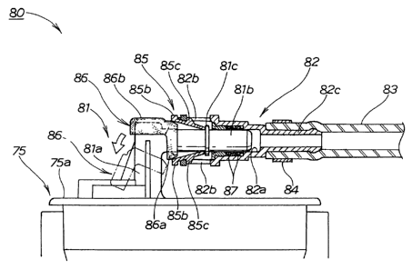
Fig. 5 is a front sectional view of the piping joint
structure according to the present invention in a disengaged
condition.
The structure of the piping joint 80 constitutes of
the joint 81 of the fuel pump as a male member, the socket 82
as a female member having one end thereof connected to the
joint 81, the fuel hose 83 fitted to the other end of the
socket 82, a band 84 for fastening the fuel hose 83, a
retainer sleeve 85 for locking the joint 81 inserted into the
socket 82, a ring member 86 fitted to the joint 81 for
preventing reduction of the diameter of the retainer sleeve
85, a plurality of 0-rings 87, 87 provided intermediately
between the joint 81 and the socket 82, and a pull tab 88 for
tentatively fixing the retainer sleeve 85 to the socket 82.
Fig. 6 is an exploded perspective view of major
component parts of the piping joint structure according to the
present invention, and shows the joint 81, the socket 82, and
the retainer sleeve 85.
The joint 81 constitutes of a vertical pipe 81a
projected from an upper portion of the housing 75a, a cylinder
portion 81b extended laterally from the vertical pipe 81a, and
a flange 81c provided on the cylinder portion 81b.
The socket 82 constitutes of a fitting hole 82a,
which is formed at one end and into which the joint 81 can be
inserted together with the retainer sleeve 85, pawl engaging
portions 82b, 82b formed in the fitting hole 82a for stopping
the retainer sleeve 85, and a connection portion 82c provided
at the other end for connecting the fuel hose 83.
The retainer sleeve 85 is a member integrally formed
from a resin and is provided with a frame body 85a, flange
portions 85b, 85b formed on the frame body 85a so as to be
abutted against one end of the socket 82,
-8-
CA 02410127 2002-10-29
JJ-11 847CA
and pawls 85c, 85c extended respectively from the flange
portions 85b, 85b for fitting to the pawl engaging
portions 82b, 82b.
The ring member 86 is a member formed of an
elastic material such as rubber and constitutes of a ring
86a to be fitted to the cylinder portion 81b of the joint
81 so as thereby to prevent reduction of the diameter of
the retainer sleeve 85, and a cap 86b to be fitted onto
the tip end of the vertical pipe 81a.
Fig. 7 is a front sectional view of the piping
joint structure according to the present invention in a
connected condition. The piping joint 80 constitutes of
the female member (socket 82) comprising the fitting hole
82a; the male member (joint 81) composing the cylinder
portion 81b to be inserted into the fitting hole 82a; the
flange 81c formed on the cylinder portion 81b; the
retainer sleeve 85 capable of being enlarged and reduced
in diameter, including the pawls 85c, 85c projecting
diametrally outwards, and to be fitted to the cylinder
portion 81b; and the pawl engaging portions 82b, 82b
provided in the female member (socket 82) for locking the
retainer sleeve 85. The piping joint 80 is such that the
male member (joint 81) can be fastened to the female
member (socket 82) by locking the pawls 85c, 85c of the
retainer sleeve 85 onto the pawl engaging portions 82b,
82b and pressing the flange 81c by the tip ends of the
pawls 85c, 85c, and the male member (joint 81) can be
detached from the female member (socket 82) by reducing
the diameter of the retainer sleeve 85 and disengaging
the pawls 85c, 85c from the pawl engaging portions 82b,
82b. The structure of the piping joint 80 in that
condition can be said that it includes the ring member 86
formed of an elastic material to be inserted between the
retainer sleeve 85 and the cylinder portion 81b in a
locked condition, and reduction of the diameter of the
- 9 -
CA 02410127 2002-10-29
JJ-11 847CA
retainer sleeve 85 is prevented by the presence of the
ring member 86.
The piping joint 80 is a joint as follow. The
male member (joint 81) can be fastened to the female
member (socket 82) by locking the pawls 85c of the
retainer sleeve 85 onto the pawl engaging portions 82b
and pressing the flange 81c by the tip ends of the pawls
85c. In addition, the male member (joint 81) can be
disengaged from the female member (socket 82) by reducing
the diameter of the retainer sleeve 85 and disengaging
the pawls 85c from the pawl engaging portions 82b. For
example, the absence of such a member as to cover the
surroundings of the piping joint 80 is preferable.
In view of this, the ring member formed of an
elastic material is provided that is inserted between the
retainer sleeve 85 and the cylinder portion 81b in the
locked condition.
Namely, the ring member 86 formed of an elastic
material is provided, which is inserted between the
retainer sleeve 85 and the cylinder portion 81b in the
locked condition. The reduction of the diameter of the
retainer sleeve 85 is prevented by the presence of the
ring member 86. Therefore, the piping joint 80 would not
be disengaged, for example, even upon a touch on the
piping joint 80 during a work. By this, the work of
connecting or detaching the piping joint 80 can be
carried out in the condition where a holding force of the
piping joint 80 is maintained.
In addition, with the ring member 86 fitted to
the male member (joint 81), the ring member 86 can be
inserted between the retainer sleeve 85 and the cylinder
portion 81b in the locked condition. Therefore, it is
possible to contrive a simplification of the structure of
the piping joint 80.
- 10 -
CA 02410127 2006-09-06
Actions of the piping joint structure as described
= above will be described below.
Figs. 8(a) and 8(b) are action illustrations of the
piping joint structure according to the present invention.
Fig. 8(a) shows the structure of a piping joint 100
according to a comparative example, and Fig. 8(b) shows the
structure of the piping joint 80 according to the embodiment.
In Fig. 8(a), the piping joint 100 is shown in the
condition where pawls 105c, 105c of a retainer sleeve 105 are
locked on pawl engaging portions 102b, 102b of a socket 102,
and a flange 101c is pressed by the tip ends of the pawls
105c, 105c, whereby the joint 101 is fitted to the socket 102
through the retainer sleeve 105.
For example, when forces for reducing the diameter
of the retainer sleeve 105 are exerted on flange portions
105b, 105b of the retainer sleeve 105 as indicated by arrows
1, 1, the forces resisting against the arrows 1, 1 are only
elastic forces of the pawls 105c, 105c of the retainer sleeve
105, so that the socket 102 can be pulled out from the joint
101 as indicated by arrow 2.
In Fig. 8(b), for example, even if forces for
reducing the diameter of the retainer sleeve 105 are exerted
on the flange portions 85b, 85b of the retainer sleeve 85 as
indicated by arrows 3, 3, forces resisting against the arrows
3, 3, namely, arrows 4, 4, are generated by the ring member
86, so that the socket 85 would not slip off from the joint 81
even in the case where a force for pulling the socket 85 off
from the joint 81 is exerted on the socket 82 as indicated by
arrow 5.
-11-
CA 02410127 2002-10-29
JJ-11 847CA
Namely, the piping joint 80 would be engaged,
for example, even upon a touch on the piping joint 80
during another work.
In addition, by intentionally pulling the cap
86b of the ring member 86 as indicated by the void arrow
in Fig. 7, the ring member 86 can be moved onto the
vertical pipe 81a as indicated by the two dot chain line.
By this, it becomes possible to reduce the diameter of
the retainer sleeve 85, and by reducing the diameter of
the retainer sleeve 85, the socket 82 can be pulled off
from the joint 81.
While disengagement of the female member
(socket 82) from the male member (joint 81) as shown in
Fig. 7 has been described in the above embodiment, this
is not limitative, and a structure in which the male
member is disengaged from the female member may be
adopted. Namely, the relationship between the male and
the female may be reversed.
In addition, the structure of the piping joint
80 mounted on the fuel tank 60 of the personal watercraft
11 (See Fig. 1) as shown in Fig. 4 has been shown in the
above embodiment, the piping joint is not limited to the
piping joint of the fuel tank in the personal watercraft
and may be a piping joint for general use.
The present invention constituted as described
above displays the following effects.
According to the present invention, the ring
member formed of an elastic material is provided, which
is inserted between the retainer sleeve and the cylinder
portion in a locked condition, and reduction of the
diameter of the retainer sleeve is prevented by the
presence of the ring member. Therefore, the piping joint
would be engaged, for example, even upon a touch on the
piping joint during a work. By this, the work of
connecting or detaching the piping joint can be carried
- 12 -
CA 02410127 2002-10-29
JJ-11 847CA
piping joint can be carried out in the condition where a
holding force of the piping joint is maintained.
Although various preferred embodiments of the
present invention have been described herein in detail,
it will be appreciated by those skilled in the art, that
variations may be made thereto without departing from the
spirit of the invention or the scope of the appended
claims.
- 13 -