Language selection

Search

Patent 2410528 Summary

Third-party information liability

Some of the information on this Web page has been provided by external sources. The Government of Canada is not responsible for the accuracy, reliability or currency of the information supplied by external sources. Users wishing to rely upon this information should consult directly with the source of the information. Content provided by external sources is not subject to official languages, privacy and accessibility requirements.

Claims and Abstract availability

Any discrepancies in the text and image of the Claims and Abstract are due to differing posting times. Text of the Claims and Abstract are posted:

  • At the time the application is open to public inspection;
  • At the time of issue of the patent (grant).
(12) Patent: (11) CA 2410528
(54) English Title: TWO BALLOON CATHETER FOR STAGED STENT EXPANSION
(54) French Title: DILATATION DE STENT EN DEUX TEMPS AU MOYEN DE DEUX BALLONNETS
Status: Expired
Bibliographic Data
(51) International Patent Classification (IPC):
  • A61F 2/958 (2013.01)
(72) Inventors :
  • RICHTER, JACOB (Israel)
(73) Owners :
  • MEDINOL LTD. (Israel)
(71) Applicants :
  • MEDINOL LTD. (Israel)
(74) Agent: MCCARTHY TETRAULT LLP
(74) Associate agent:
(45) Issued: 2007-05-01
(86) PCT Filing Date: 2001-06-13
(87) Open to Public Inspection: 2001-12-20
Examination requested: 2003-01-17
Availability of licence: N/A
(25) Language of filing: English

Patent Cooperation Treaty (PCT): Yes
(86) PCT Filing Number: PCT/IL2001/000543
(87) International Publication Number: WO2001/095833
(85) National Entry: 2002-11-26

(30) Application Priority Data:
Application No. Country/Territory Date
60/211,642 United States of America 2000-06-14

Abstracts

English Abstract


A catheter with two balloons for implanting a stent without flaring at the
ends of the stent during implantation has an outer balloon overlying an inner
balloon. The length of the inner balloon is shorter than the length of the
outer balloon and shorter than a stent which is mounted over both balloons.
Upon inflation of the inner balloon, the inner balloon expands only the center
of the stent. After the center of the stent is expanded, further application
of pressure bursts the inner balloon allowing application of pressure to the
outer balloon. The outer balloon is then inflated, expanding the ends of the
stent.


French Abstract

L'invention concerne un cathéter à deux ballonnets permettant d'implanter un stent sans évasement au niveau des extrémités dudit stent pendant son implantation, qui comprend un ballonnet extérieur recouvrant un ballonnet intérieur. La longueur du ballonnet intérieur est inférieure à la longueur du ballonnet extérieur, et inférieure à celle d'un stent monté sur les deux ballonnets. Lors de son gonflage, le ballonnet intérieur se dilate uniquement au centre du stent. Une fois le centre du stent dilaté, une application de pression additionnelle fait éclater le ballonnet intérieur, ce qui permet d'appliquer la pression au ballonnet extérieur. Le ballonnet extérieur est alors gonflé, et dilate les extrémités du stent.

Claims

Note: Claims are shown in the official language in which they were submitted.


WHAT IS CLAIMED IS
1. A stent and balloon catheter in combination comprising:
a balloon catheter with a first (6) and a second (8)
balloon, the second balloon (8) overlaying the first
balloon (6), the second balloon(8) having a length which is
greater than a length of the first balloon (6); and
an expandable stent (14) mounted over the first and
second catheter balloons,
wherein a burst pressure of the first balloon (6) is
less than a burst pressure of the second balloon (8).
2. The combination according to claim 1 wherein the burst
pressure of the inner balloon (6) is less than 10
atmospheres.
3. The combination according to claim 1 or 2 wherein the burst
pressure of the inner balloon (6) is approximately 5
atmospheres.
4. The combination according to claim 1, 2 or 3 wherein the
burst pressure of the outer balloon (8) is greater than 10
atmospheres.
5. The combination according to any one of claims 1-4 wherein
the outer balloon (8) is formed of a non-compliant
material.
6. The combination according to any one of claims 1-5 wherein
the inner balloon(6) is formed of a non-compliant material.
7. The combination according to any one of claims 1-6 wherein
the catheter shaft 2) has a guidewire port located adjacent
the balloons.


8. The combination according to any one of claims 1-7 wherein
the burst pressure of the first balloon (6) is at least 5
atmospheres less than the burst pressure of the second
balloon (8).
9. The combination according to any one of claims 1-8 wherein
a length of the first balloon (6) is less than a length of
the stent (14).
10. The combination according to any one of claims 1-9 wherein
a length of the second balloon (8) is greater than a length
of the stent (14).

Description

Note: Descriptions are shown in the official language in which they were submitted.


CA 02410528 2006-08-30
TWO BALLOON CATHETER FOR STAGED STENT EXPANSION
FIELD OF THE INVENTION
The present invention relates generally to
catheter balloons for implanting stents. More
particularly, the present invention relates to a catheter
balloon which utilizes two balloons coaxially disposed
within one another.
BACKGROUND OF THE INVENTION
It is well known to use a balloon catheter to
intraluminally deliver and implant a stmt. Typically, to
implant a stent with a balloon catheter, the unexpanded
stent is disposed around the deflated balloon of a balloon
catheter. The balloon is then delivered to the desired
implantation site and inflated. The inflation of the
balloon expands the stent, implanting it at the desired
location. '
One shortcoming of conventional balloon catheters is
that they may cause the ends of the stmt to flare out
during implantation. This flaring out is referred to as
"dogboning". Dogboning causes at least two undesirable
effects. First, dogboning exacerbates any foreshortening
of the stent during expansion. Second, dogboning causes
the edges of the end of the stent to project in a direction
perpendicular to the wall of the vessel in which the stent
is being implanted. These projecting edges potentially
increase trauma to the wall of the lumen.
SUI~IARY OF THE INVENTION
Embodiments of the present invention include a balloon
catheter with two balloons is disclosed. An inner balloon
is shorter than an outer balloon, and also shorter than a
1


CA 02410528 2002-11-26
WO 01/95833 PCT/ILO1/00543
st mt which is to be implanted. The outer balloon overlays
the inner balloon, and is longer that the stmt.
To implant the stmt, the catheter is delivered to a
desired site in a vessel. Pressure is applied to the inner
balloon, inflating the balloon and implanting the central
portion of the stmt. Further increases in pressure
rupture the inner balloon. Because the outer balloon
overlays the inner balloon, the pressure inflates the outer
balloon, expanding the remainder of the st mt. The
balloons may then be deflated and removed, leaving the
implanted stmt in the vessel.
BRIEF DESCRIPTION OF THE DRAWINGS
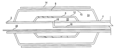
Fig. 1 shows a cross-sectional view of an embodiment
of a catheter balloon assembly constructed according to the
principles of the present invention which is in the
deflated condition;
Fig. 2 shows a cross-sectional view of the catheter of
Fig. 1 after partial inflation; and
Fig. 3 shows a cross-sectional view of the catheter of
Fig. 1 after full inflation.
DETAINED DESCRIPTION OF THE INVENTION
Fig. 1 shows a schematic view of an embodiment of a
catheter balloon constructed in accordance with the
principles of the present invention. The details of the
catheter have not been included here, as they are well
known to those skilled in the art. The precise
configurations of the catheter shaft, guidewire lumen, and
inflation lumen can be chosen as desired. For example, the
catheter may be designed as a rapid-exchange system or as
an over-the-wire system. The balloon catheter includes a
catheter shaft 2. An inner balloon 6 is sealed to the
outer surface 4 of the catheter shaft 2. The length of the
2


CA 02410528 2002-11-26
WO 01/95833 PCT/ILO1/00543
inner balloon is chosen so that it is less than the length
of the stmt which it is designed to implant. The inner
balloon 6 may be formed of a non-compliant material.
An outer balloon 8 is disposed around the inner
balloon 6. The inner surface 10 of the outer balloon is
immediately adjacent to the outer surface of the inner
balloon. The two surfaces are permitted to move with
respect to each other. The outer balloon 8 is sealed to
the outer surface 4 of the catheter shaft 2 at the ends of
the balloon. The outer balloon 8 may be formed of a
non-compliant material. Tn the illustrated embodiment, the
length of the outer balloon is chosen so that it is
approximately 4 mm longer than the stmt. In this and
other embodiments, when the stmt is crimped around the
deflated balloon, the same amount of balloon may extend
past the stmt on each side - - i.e. the balloon may, for
example, extend past the stmt by 2mm on each side.
An inflation lumen 16 is located within the catheter
shaft 4. The inflation lumen 16 is in fluid communication
with the interior 20 of the inner balloon 6 through an
aperture 18 in the catheter shaft 4. A pressurized medium,
such as saline, may be introduced into the inflation lumen
16 to inflate the inner balloon. The space between the
inner balloon and the outer balloon is not provided with an
inflation lumen.
In operation, a guidewire 22 may be routed to the
desired inflation location. The balloon catheter, the
catheter shaft 4 of which has a guidewire port located
adjacent the balloons, with a crimped st mt may be then
placed over the guidewire 22 and delivered to the desired
location. A pressurized medium is introduced into the
inflation lumen. The pressurized medium passes into the
interior 20 of the inner balloon 6, and begins to inflate
the inner balloon 6. The inner balloon 6 applies pressure
to both the stmt 14 and the outer balloon 8. Typically,
3


CA 02410528 2002-11-26
WO 01/95833 PCT/ILO1/00543
at approximately 3 or 4 atmospheres (depending on the
particular stmt design chosen), the stmt 14 begins to
expand. As shown in Fig. 2, because the inner balloon 6 is
shorter than the stmt 14, only the middle portion of the
stmt 14 begins to expand. At, for example, approximately
five atmospheres, the stmt 14 is sufficiently expanded so
that it is implanted into the vessel wall.
As shown in Fig. 3, upon further application of the
pressurized medium to the inflation lumen, the inner
balloon 6 ruptures. The burst pressure of the inner
balloon may be less than 10 atmospheres, and in some
embodiments be approximately 5 atmospheres, for example.
Rupture of the inner balloon 6 allows fluid communication
.between the inflation lumen 16 and the cavity formed
between the outer balloon and the inner balloon.
When further pressure is applied to the inflation
lumen, the outer balloon expands the entire length of the
stmt. The operator may then apply as much pressure as
desired, up to the burst pressure of the outer balloon to
firmly implant the stmt. Typically, the burst pressure of
the outer balloon should be greater than that of the inner
balloon. Thus, for example, in a particular embodiment the
burst pressure of the inner balloon may be selected to be,
for example, 5 atmospheres, and the burst pressure of the
outer balloon may be selected to be equal to 10
atmospheres, i.e.,to give an approximately 5 atmosphere
difference.
The balloons may then be deflated, and the catheter
and guidewire may then by removed.
In the foregoing specification, the invention has been
described with reference to specific exemplary embodiments.
It will, however, be evident that various modifications
and changes may be made thereunto without departing from
the broader spirit and scope of the invention as set forth
in the appended claims. The specification and drawings are
4


CA 02410528 2002-11-26
WO 01/95833 PCT/ILO1/00543
accordingly to be regarded in an illustrative rather than a
restrictive sense.

Representative Drawing
A single figure which represents the drawing illustrating the invention.
Administrative Status

For a clearer understanding of the status of the application/patent presented on this page, the site Disclaimer , as well as the definitions for Patent , Administrative Status , Maintenance Fee  and Payment History  should be consulted.

Administrative Status

Title Date
Forecasted Issue Date 2007-05-01
(86) PCT Filing Date 2001-06-13
(87) PCT Publication Date 2001-12-20
(85) National Entry 2002-11-26
Examination Requested 2003-01-17
(45) Issued 2007-05-01
Expired 2021-06-14

Abandonment History

There is no abandonment history.

Payment History

Fee Type Anniversary Year Due Date Amount Paid Paid Date
Application Fee $300.00 2002-11-26
Request for Examination $400.00 2003-01-17
Maintenance Fee - Application - New Act 2 2003-06-13 $100.00 2003-01-17
Registration of a document - section 124 $100.00 2003-02-26
Maintenance Fee - Application - New Act 3 2004-06-14 $100.00 2003-05-27
Maintenance Fee - Application - New Act 4 2005-06-13 $100.00 2005-06-09
Maintenance Fee - Application - New Act 5 2006-06-13 $200.00 2006-06-12
Final Fee $300.00 2007-02-09
Maintenance Fee - Patent - New Act 6 2007-06-13 $200.00 2007-05-30
Maintenance Fee - Patent - New Act 7 2008-06-13 $200.00 2008-05-20
Maintenance Fee - Patent - New Act 8 2009-06-15 $200.00 2009-05-19
Maintenance Fee - Patent - New Act 9 2010-06-14 $200.00 2010-05-17
Maintenance Fee - Patent - New Act 10 2011-06-13 $250.00 2011-05-17
Maintenance Fee - Patent - New Act 11 2012-06-13 $250.00 2012-05-17
Maintenance Fee - Patent - New Act 12 2013-06-13 $250.00 2013-05-17
Maintenance Fee - Patent - New Act 13 2014-06-13 $250.00 2014-06-09
Maintenance Fee - Patent - New Act 14 2015-06-15 $250.00 2015-06-08
Maintenance Fee - Patent - New Act 15 2016-06-13 $450.00 2016-06-06
Maintenance Fee - Patent - New Act 16 2017-06-13 $450.00 2017-06-12
Maintenance Fee - Patent - New Act 17 2018-06-13 $450.00 2018-06-11
Maintenance Fee - Patent - New Act 18 2019-06-13 $450.00 2019-06-07
Owners on Record

Note: Records showing the ownership history in alphabetical order.

Current Owners on Record
MEDINOL LTD.
Past Owners on Record
RICHTER, JACOB
Past Owners that do not appear in the "Owners on Record" listing will appear in other documentation within the application.
Documents

To view selected files, please enter reCAPTCHA code :


To view images, click a link in the Document Description column. To download the documents, select one or more checkboxes in the first column and then click the "Download Selected in PDF format (Zip Archive)" or the "Download Selected as Single PDF" button.

List of published and non-published patent-specific documents on the CPD .

If you have any difficulty accessing content, you can call the Client Service Centre at 1-866-997-1936 or send them an e-mail at CIPO Client Service Centre.


Document
Description 
Date
(yyyy-mm-dd) 
Number of pages   Size of Image (KB) 
Claims 2006-04-18 2 45
Abstract 2002-11-26 1 59
Claims 2002-11-26 3 96
Drawings 2002-11-26 3 56
Description 2002-11-26 5 188
Representative Drawing 2003-02-20 1 8
Cover Page 2003-02-21 1 39
Claims 2003-02-13 3 97
Cover Page 2007-04-13 1 39
Description 2006-08-30 5 185
Prosecution-Amendment 2006-04-18 4 98
Correspondence 2004-07-21 1 12
Correspondence 2004-07-21 1 18
PCT 2002-11-26 5 186
Assignment 2002-11-26 2 86
Prosecution-Amendment 2003-01-17 1 37
Correspondence 2003-02-18 1 24
Fees 2003-01-17 1 37
Prosecution-Amendment 2003-02-13 2 57
Assignment 2003-02-26 2 72
PCT 2002-11-27 2 99
Fees 2003-05-27 1 31
Correspondence 2004-06-30 1 16
Correspondence 2004-06-29 3 74
Correspondence 2004-07-21 1 15
Correspondence 2004-06-15 3 64
Correspondence 2004-07-21 1 17
Fees 2005-06-09 1 27
Prosecution-Amendment 2005-10-17 2 61
Prosecution-Amendment 2005-11-03 2 44
Fees 2006-06-12 1 29
Correspondence 2006-07-14 1 14
Prosecution-Amendment 2006-04-19 4 106
Prosecution-Amendment 2006-07-19 8 220
Correspondence 2006-08-08 1 23
Correspondence 2006-08-30 2 73
Correspondence 2007-02-09 1 29