Language selection

Search

Patent 2410776 Summary

Third-party information liability

Some of the information on this Web page has been provided by external sources. The Government of Canada is not responsible for the accuracy, reliability or currency of the information supplied by external sources. Users wishing to rely upon this information should consult directly with the source of the information. Content provided by external sources is not subject to official languages, privacy and accessibility requirements.

Claims and Abstract availability

Any discrepancies in the text and image of the Claims and Abstract are due to differing posting times. Text of the Claims and Abstract are posted:

  • At the time the application is open to public inspection;
  • At the time of issue of the patent (grant).
(12) Patent Application: (11) CA 2410776
(54) English Title: AIR POWERED LIFTING SUSPENSION SYSTEM
(54) French Title: SYSTEME DE SUSPENSION PNEUMATIQUE DE LEVAGE
Status: Dead
Bibliographic Data
(51) International Patent Classification (IPC):
  • B60G 17/052 (2006.01)
  • B60G 3/14 (2006.01)
  • B60G 11/56 (2006.01)
  • B60G 15/06 (2006.01)
(72) Inventors :
  • LAVOIE, ANDRE (Canada)
(73) Owners :
  • LAVOIE, ANDRE (Canada)
(71) Applicants :
  • LAVOIE, ANDRE (Canada)
(74) Agent:
(74) Associate agent:
(45) Issued:
(22) Filed Date: 2002-11-25
(41) Open to Public Inspection: 2004-05-25
Availability of licence: N/A
(25) Language of filing: English

Patent Cooperation Treaty (PCT): No

(30) Application Priority Data: None

Abstracts

English Abstract


The present invention is air powered lifting suspension system allowing to
lower and adjust a trailer to the ground level.


Claims

Note: Claims are shown in the official language in which they were submitted.


CLAIM(S):

The embodiments of the invention for which an exclusive property or
privilege is claimed, are defined as follows:

1. Air powered lifting suspension system allowing to lower and adjust a
trailer to the ground level, which comprising a first arm formed with an
elongated part member including hole which is engaged into a cylindrical
part member including holes allowing by means of a first rod and first bolt
to be connected to frame of said trailer, and of a U-shaped member
including holes formed under each end of said first arm;
said U-shaped member formed under the upper end of each said first arm is
engaged onto a connecting means formed onto each balloon, which
allows to connected each said balloon to said first arm by means of a second
rod and second bolt, wherein an aperture formed therein allows to a safety
rod to pass through said first arm and said frame, and which is blocked in
position by a clip member;
a connecting means formed under each said balloon is engaged into a
U-shaped member which allows to connect each said balloon to said frame
of trailer by means of said second rod and said second bolt;
said U-shaped member formed under the lower end of each said first arm is
engaged onto the upper connecting means formed onto each shock
absorber, which is connected therein by means of said second rod and
second bolt;
the lower connecting means formed onto each said shock absorber is


engaged into a U-shaped member formed on top of second arm, which is
connected to each said shock absorber by means of said second rod and
said second bolt;

the lower end of each said second arm is formed with a longer rod passing
through the ring members and a part member including spaced and aligned
holes, which are maintained in position by means of said second bolt and
connected at each wheel of trailer; and
the upper end of each said second arm is formed with a structural part
member including hole which is engaged into a cylindrical part member
including holes and connected to said frame of trailer by means of
said first rod and said first bolt.

2. The system of the claim 1 allows by means of a compressor to distribute
independently the air pressure to each lifting suspension system by means
of tubes, wherein each said lifting suspension system is provided with two
arms.


Description

Note: Descriptions are shown in the official language in which they were submitted.


CA 02410776 2002-11-25
TITLE: Air powered lifting suspension system
ABSTRACT OF THE D1SC',LOSURE:
The present disclosure refer°s to air powered lifting suspension
system
allowing to lower and adjust ;~ trailer to the ground level.
BACKGROUND OF THF, INVENTION:
1) Field of the invention:
The present invention relates to air powered lifting suspension system
allowing to lower and adjust a trailer to the ground level.
2) Descriution of related art:
A search of prior art records has unveiled the following patents:
US 5,549,322 issued in 1996 to Hauri.
As can be seen the patent mentioned above is probably the most
relevant.
The proposed system is air powered lifting suspension system allowing to
lower and adjust a trailer to the ground level.
It has been discovered that the present invention described herein
allows by the assembling of the components to lower and adjust a trailer to
the ground level.
Brief description of the several views of the drawin~lsl:
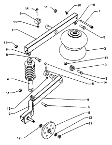
Figure 1 is a perspective vicaw of air powered lifting suspension
system;

CA 02410776 2002-11-25
Figure 2 is a perspective view of air powered lifting suspension system
showing a lowered trailer t:o the ground level;
Figure 3 is a side view thereof;
Figure 4 is a side view of air powered lifting suspension system
showing a trailer before to be lowered to the ground level;
Figure 5 is a perspective view showing the components of air powered
lifting suspension system assembled to a trailer;
Figure 6 is a side view thereof; and
Figure 7 is an exploded view of air powered lifting suspension system.
Detailed descriution of the invention:
Referring to the drawings in more detail, it may be seen that the present
invention allows when the air is taken out from the balloons (3) to lower
and adjust a trailer to the ground level.
As shown in figures 1 to 7, the air pressure of a compressor (15) is
distributed independently to each lifting suspension system by means of
tubes (16), which each lifting suspension system is provided with two arms
(1)(2).
The first arm (1) is formed with an elongated part member including hole
which is engaged into a cylindrical part member (6) including holes
allowing by means of a first rod (14) and first bolt (13) to be connected to
frame of trailer shown in phantom lines, and of a U-shaped member (9)
including holes formed under each end of first arm (l).
The U-shaped member (9) formed under the upper end of each first arm (1)

CA 02410776 2002-11-25
is engaged onto a connecting means formed onto each balloon (3), which
allows to connected each balloon (3) to first arm (1) by means of a second
rod (8) and second bolt (11;x, and which an aperture formed therein allows to
a safety rod (7) to pass through first arm (1) and frame, and which is
blocked in position by a clip member (10).
A connecting means formed under each balloon (3) is engaged into a
U-shaped member (9) which allows to connect each balloon (3) to frame of
trailer by means of a second rod (8) and second bolt (11).
The U-shaped member (9) formed under the lower end of each first arm (1)
is engaged onto the upper connecting means formed onto each shock
absorber (4), which is connected therein by means of a second rod (8) and
second bolt (11).
The lower connecting means formed onto each shock absorber (4) is
engaged into a L1-shaped member (9) formed on top of second arm (2),
which is connected to each shock absorber (4) by means of a second rod
(8) and second bolt (11).
The lower end of each second arm (2) is formed with a longer rod passing
through the ring members ( 1~) and a part member (5) including spaced and
aligned holes, which are maintained in position by means of second
bolt (11) and connected at each wheel of trailer shown in phantom lines.
The upper end of each second arm (2) is formed with a structural part
member including hole which is engaged into a cylindrical part member (6)
including holes and connected to frame of trailer by means of a first

CA 02410776 2002-11-25
rod (14) and first bolt (13).
Although only a single embodiment of the present invention has been
described and illustrated, the present invention is not limited to the
features
of this embodiment, but includes all variations and modifications within the
scope of claims attached hereto without departing from the spirit of the
invention.

Representative Drawing
A single figure which represents the drawing illustrating the invention.
Administrative Status

For a clearer understanding of the status of the application/patent presented on this page, the site Disclaimer , as well as the definitions for Patent , Administrative Status , Maintenance Fee  and Payment History  should be consulted.

Administrative Status

Title Date
Forecasted Issue Date Unavailable
(22) Filed 2002-11-25
(41) Open to Public Inspection 2004-05-25
Dead Application 2005-11-25

Abandonment History

Abandonment Date Reason Reinstatement Date
2004-11-25 FAILURE TO PAY APPLICATION MAINTENANCE FEE

Payment History

Fee Type Anniversary Year Due Date Amount Paid Paid Date
Application Fee $150.00 2002-11-25
Owners on Record

Note: Records showing the ownership history in alphabetical order.

Current Owners on Record
LAVOIE, ANDRE
Past Owners on Record
None
Past Owners that do not appear in the "Owners on Record" listing will appear in other documentation within the application.
Documents

To view selected files, please enter reCAPTCHA code :


To view images, click a link in the Document Description column. To download the documents, select one or more checkboxes in the first column and then click the "Download Selected in PDF format (Zip Archive)" or the "Download Selected as Single PDF" button.

List of published and non-published patent-specific documents on the CPD .

If you have any difficulty accessing content, you can call the Client Service Centre at 1-866-997-1936 or send them an e-mail at CIPO Client Service Centre.


Document
Description 
Date
(yyyy-mm-dd) 
Number of pages   Size of Image (KB) 
Abstract 2002-11-25 1 6
Description 2002-11-25 4 123
Claims 2002-11-25 2 67
Drawings 2002-11-25 7 172
Representative Drawing 2003-01-15 1 12
Cover Page 2004-04-30 1 30
Correspondence 2002-12-30 1 11
Assignment 2002-11-25 3 121