Note: Descriptions are shown in the official language in which they were submitted.
CA 02411041 2003-O1-20
DISC FURROW OPENER SCRAPER P~.SITIONING SYSTEM
IS
This invention is in the field of furrow openers for agricultural operations,
and in particular
adjustment mechanisms to provide satisfactory operation of disc furrow openers
as the disc
wears.
2o BACKGROUND
In agricultural seeding operations agricultural materials, such as seed and
fertilizer, are
deposited in furrows that are opened in the soil by a furrow opener. The
furrow openers are
attached to an implement frame and pulled along a Held.
Agricultural materials are carried from a storage tank or the like by one or
more tubes that
have output ends attached to the furrow opener. The agricultural materials
pass from the
CA 02411041 2003-O1-20
_ page ~ _
output end of the tube into a seed boot or the like attached to the furrow
opener that directs
the material into the furrow. For liquid fertilizer, the output end of the
tube may simply be
oriented such that the liquid drops into the furrow. Double shoot furrow
openers are also
available where two furrows are formed and different agricultural materials
are directed into
each furrow.
Although such furrow openers are known in a wide varieky of configurations,
one common
configuration includes a rotating disc. The disc is typically rotatably
attached, in a generally
upright orientation, to an arrn which in turn is pivotally attached to the
frame about a
1o substantially horizontal axis su as to allow the disc to move up and down.
The furrow opener
apparatus will include some means, such as a spring, hydraulic cylinder, or
the like, to bias
the arm downward such that the lower edge ofthe disc engages the ground to
create a fiurow.
The rotational axis of the disc is typically oriented at an angle to the
direction of travel such
15 that when the disc is pushed down into the soil, soil is moved laterally
along a leading face of
the disc, and a groove or furrow is thus created adjacent to the trailing face
of the disc. The
output end of the tube is attached to the furrow opener adjacent to the
trailing face of the disc
and directs agricultural materials into the furrow just behind the trailing
face.
2o Soil and debris sometimes clings to the trailing face of the disc and can
prevent the
agricultural materials from falling into the furrow, or jam in the output end
plugging the boot
or tube. The agricultural material generally falls down adjacent to the
trailing face, and so
such soil and debris blocks its path, with the result that the agricultural
material falls on the
ground adjacent to the furrow, or only part way into the furrow. Ideally the
agricultural
25 material falls right to the bottom of the furrow, and it is the objective
of furrow opener design
to have the disc and material outlet oriented relative to each other to
achieve that end.
CA 02411041 2003-O1-20
-fage3-
To clean the soil and debris from the trailing face of the disc a scraper is
typically provided
with a blade parallel to, and closely adjacent to or touching, the trailing
face. Offen the
scraper is biased against the trailing face. The scraper is located generally
against a lower
portion of the trailing face of the disc. The blade of the scraper is located
generally across
S the trailing face so that a substantial portion of the face from near the
outer edge of the disc
towards the center thereof is scraped clean.
The scraper can also serve to prevent soil from falling back into the furrow
before the
agricultural material is deposited. 'Typically the scraper is oriented at an
angle outward from
the blade, and the agricultural material output is located behind the scraper
such that the path
of the agricultural material into the furrow is protected from soil and debris
that is disturbed
by the disc or scraper, and such that the agricultural material is confined
adjacent to the
trailing face, and conveniently between the scraper and the trailing face of
the disc, and so
falls into the furrow. For satisfactory operation, the disc, tube and scraper
must be oriented
is in a cooperating relationship to each other so that the agricultural
material falls into the
furrow.
Examples of furrow openers incorporating scrapers and means for delivering
agricultural
materials to a furrow are disclosed in United States Patent Numbers 6,024,179
to Bourgault,
6,260,632 to Bourgault et al., and 6,237,696 to Mayerle.
As the disc is used, it wears down and its diameter becomes smaller. The
scraper does not
typically wear in the same way, with the result that, as the disc becomes
smaller, the scraper
extends beyond the edge of the disc such that a portion of the scraper engages
the soil instead
of the trailing face of the disc. The scraper no longer engages the trailing
face of the disc
properly because of interference from the soil. Since it is desirable to
scrape the trailing face
fairly close to the disc edge, the disc can only wear a fairly small amount
before the scraper
CA 02411041 2003-O1-20
-Page4-
extends beyond the disc edge and proper operation ofthe scraper is inhibited.
'The disc must
then be replaced, requiring considerable expense and labor.
SUMMARY OF THE INVENTION
It is an object of the present invention to provide a disc furrow opener that
overcomes
disadvantages associated with known furrow openers. It is a further object of
the present
invention to provide such a disc furrow opener wherein the scraper that cleans
the trailing
face of the disc can be adjusted so that as the disc wears and gets smaller,
the scraper can be
moved inward along the trailing face so that the scraper does not extend past
the edge of the
disc.
It is a further object of the present invention to provide such a disc furrow
opener wherein the
output end of the tube that delivers agricultural material to the furrow can
also be moved so
that the cooperating relationship o.f the disc, scraper, and the output end of
the tube can be
maintained.
The present invention provides, in one aspect, a furrow opener apparatus
adapted for
attachment to an implement for movement along the ground in an operating
travel direction.
The apparatus comprises a disc rotatably attached to the apparatus in a
generally upright
orientation at an angle to the operating travel direction such that when a
leading face of the
disc engages the ground, a furrow is formed adjacent to a trailing face of the
disc. A scraper
has a scraper blade oriented substantially parallel to the trailing face of
the disc, and mounted
such that the scraper blade is oriented in close proximity to or touching a
lower portion of the
trailing face adjacent to an outer edge of the disc. The scraper is adjustably
attached to the
apparatus such that the scraper blade can be moved inward along the trailing
face away from
the outer edge of the disc while being maintained substantially parallel to
the trailing face of
CA 02411041 2003-O1-20
-fage5-
the disc and in close proximity to or touching the trailing face of the disc.
In a second aspect the invention provides a furrow opener apparatus adapted
for attachment
to an implement for movement along the ground in an operating travel
direction. The
apparatus comprises an arm adapted for pivotal attachment at a front end
thereof to the
implement, and a disc rotatably attached to a rear portion of the arm in a
generally upright
orientation at an angle to the operating travel direction such that when a
leading face of the
disc engages the ground, a furrow is formed adjacent to a trailing face of the
disc. A scraper
having a scraper blade is attached t~o a scraper bracket, and the scraper
bracket is attached to
the arm such that the scraper blade is oriented substantially parallel to the
trailing face of the
disc in close proximity to or touching a lower portion of the trailing face
adj acent to an outer
edge of the disc. The attachment of the scraper bracket to the arm is
adjustable such that the
scraper bracket can be moved along the arm and can b~; locked to the aim in a
desired
location relative to the arm, such that the scraper blade can be moved inward
along the
trailing face as the disc wears and such that the scraper blade is maintained
substantially
parallel to the trailing face of the disc and in close proximity to or
touching the trailing face
of the disc as the scraper blade moves inward.
The furrow opener of the invention extends the life of the disc by allowing
the scraper to be
moved inward as the disc wears. 'The scraper scrapes a substantial portion of
the trailing face
of the disc, but there is room to move it inward along the trace of the disc
as the disc wears.
Preferably the tube for depositing agricultural materials into the furrow is
attached to the
apparatus so that the cooperating relationship between the tube and scraper
adjacent to the
trailing face of the disc is maintained during movement. An adjustable biasing
force on the
scraper blade can be provided as well.
DESCRIPTION OF THE DRAWINGS:
CA 02411041 2003-O1-20
-Pagefi-
While the invention is claimed in the concluding portions hereof, preferred
embodiments are
provided in the accompanying detailed description which may be best understood
in
conjunction with the accompanying diagrams where like parks in each of the
several diagrams
°> are labeled with like numbers, and where:
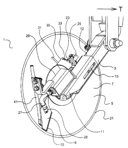
Fig. 1 is a perspective right side view of a disc furrow opener apparatus of
the
invention with the scraper located in the proper operating position with a new
disc;
to Fig. 2 is a perspective right side view of a disc furrow opener apparatus
of Fig. l with
the scraper located at the inzier end of its range of movement indicating that
considerable wear can be sustained by the disc of' prior to replacement;
Fig. 3 is a perspective left side view of a disc furrow opener apparatus of
Fig. 1 with
15 th;e disc removed to facilitate observation of the parts of the apparatus;
Fig. 4 is a schematic top view showing the alignment of the disc, scraper,
scraper
shaft, housing, arm, and coil spring.
2o DETAILED DESCRIPTION O>f THE ILLUSTRATED EMBODIMENTS:
Figs. 1- 3 illustrate a furrow opener apparatus 1 adapted for attachment to an
implement for
movement along the ground in an operating travel direction T. The apparatus l
comprises
an arm 3 adapted for pivotal attachment at a front end thereof to the
implement;
A disc 5 is rotatably attached to a rear portion of the arm 3 in a generally
upright orientation
at an angle N to the operating travel direction T such that when a leading
face of the disc 5
CA 02411041 2003-O1-20
f age 7
engages the ground, a furrow is formed adjacent to a trailing face 7 of the
disc 5. The disc 5
is illustrated as substantially vertical for clarity ofillustration, however
discs that are oriented
at an angle to the vertical as well as to the operating travel direction T are
known and can be
used with the apparatus 1 of the inventioan as well.
A scraper 9 has a scraper blade 10 and is attached to a scraper bracket 11.
The scraper
bracket 11 is adjustably attached to the arm 3 such that the scraper bracket
11 can be moved
along the arm 3 and can be locked to the arm 3 in a desired location relative
to the arm 3. In
the illustrated embodiment the scraper bracket 1 I comprises a sleeve 12 that
defines a slot 13
on each side thereof, and the scraper bracket 11 is adjustably attached to the
arm 13 by a bolt
1 S through the slot 13 and a corresponding hole in the arm 3. Other
mechanisms for such
adjustable attachment are known and could be utilized as well. The
scraperblade 10 can thus
be moved inward along the trailing face 7 of the disc 5 as the disc 5 wears.
For proper operation, the scraper bracket 11 should be maintained in a
selected relationship
with the arrn 3. To ensure that the scraper bracket 11 does not slip out of
the desired position
on the arm 3 the slot 13 on one side of the sleeve 12 is notched, as
illustrated in Fig. 3, and
the bolt 15 is a carriage bolt comprising a square head 17 that engages
notches 19 in the slot
13. Thus, rather than simply securing the scraper bracket 11 by tightening the
bolt 15 to
2o exert friction between the sleeve 12 anti the bolt 15 and arm 3, the square
head 17 is engaged
in notches 19 so that as long as the bolt 1 S is tight enough to maintain the
engagement, the
sleeve 12 cannot move with respect to the hole in the arm 3.
The scraper 9 is attached to a rear portion of the scraper bracket 11 behind a
center of the
disc 5 and extends down behind the center of the disc 5. The scraper blade 10
is oriented
substantially parallel to the trailing face 7 of the disc S in close proximity
to or touching a
lower portion of the trailing face 7 adjacent to an outer edge 21 of the disc
5, as best seen in
CA 02411041 2003-O1-20
° Page ~
Figs. l and 4.
In the illustrated embodiment the apparatus 1 comprises a bias element,
illustrated as coil
spring 23, attached to the scraper bracket 11 and operative to exert a bias
force against the
scraper 9 to push the scraper blade 10 against the trailing face 7 of the disc
5. The scraper 9
is attached to a scraper shaft 25 that extends through and engages the coil
spring 23 such that
the coil spring 23 exerts the bias force on the scraper shaft 25. As
illustrated, a shaft
extension 27 extends down from a rear end of the scraper shaft 25 for
attachment of the
scraper 9. The illustrated scraper 9 is rotatably attached to the shaft
extension 27 by
1 o mounting rings 28 such that the scraper blade 10 can follow the trailing
face 7 of the disc 5
when the disc 5 is somewhat warped or distorted, as is not uncommon during
operation.
The scraper shaft 25 pivots about a longitudinal axis LA that is oriented
substantiallyparallel
to a rotational plane of the disc 5, as seen in Fig. 4. The scraper bracket 11
comprises a
housing 29 attached to the sleeve 12 at an angle that corresponds to the angle
N to the
direction of travel T. The scraper shaft 25 is pivotally mounted in the
housing 29 and
extends out the front end of the housing 29 to engage the coil spring 23. The
coil spring 23 is
attached at the front end to the scraper shaft 25, and a rear leg 31 of the
coil spring 23 is
engaged in one of a plurality of notches 33 in an adjustment member 35
attached to the end
of the housing 29. The bias force on the scraper 9 is adjusted by placing the
leg 31 in
different notches 33.
The sleeve 12 is moved inward along the arm 3 as the disc S wears. As best
seen in Fig. 4,
the scraper shaft 25 is maintained parallel to the disc 5 as the sleeve 12
moves forward. The
scraper shaft 25 also moves slightly clcaser to the disc S as the sleeve 12
moves forward, but
the scraper blade 10 is maintained parallel to the trailing face 7 of the disc
5. The scraper
blade 10 is also maintained touching the trailing face '7 by the bias force of
the coil spring 23.
CA 02411041 2003-O1-20
-Paged-
Although the movement of the scraper shaft 25 closer to the disc S is quite
small, if
necessary the leg 31 of the coil spring 23 can be moved to a different notch
33 to maintain
the correct bias force.
Other mechanisms to provide a bias force on the scraper blade 10 could be
provided as well.
Alternatively, an adjusting mechanism could be provided to maintain the
scraper blade 10 in
close proximity to the disc 5 if it is desired that the scraper blade 10 not
exert a force on the
disc 5. Such forces, if too high, can cause excessive rolling resistance. Both
configurations
are used in prior art disc furrow openers.
The scraper 9 and bias mechanism are attached to the scraper bracket 11 such
that both move
along the arm 3 as the disc 5 wears. In order to maintain, during adjustment
for disc wear,
the preferred cooperating relationship between the scraper 9 and a tube 41 for
depositing
agricultural material into the furrow, the tube 41 is also attached to the
scraper bracket 11
such that the tube 41 also moves inward along the arm 3 when the scraper 9,
and bias
mechanism move inward. The output end of the tube 41 is located substantially
between the
txailing face 7 of the disc 5 and the scraper 9 in a preferred location for
ensuring the
agricultural material falls into the furrow.
2o The useful life of the disc S is extended, since the scraper 9, tube 41,
and bias mechanism can
all be moved inward together along the trailing face 7 of the disc S as the
disc wears. 'Thus
the scraper blade 10 can be located adjacent to the outside edge 21 of the
disc 5, and
progressively moved inwards as xequired. The disc S will create a satisfactory
furrow
through a considerable range of reduced diameter, and the apparatus of the
invention allows
adjustment to maintain satisfactory opexation of the scraper 9 and proper
delivery of
agricultural material from the tube 41 to the furrow through a substantial
range of diameters.
CA 02411041 2003-O1-20
- Page 10 -
Fig. 1 illustrates the scraper 9 located in an operating position on a new
disc 5. Fig. 2
illustrates the scraper 9 moved inward along the trailing face 7 to its inner
limit as indicated
by the holes in the arm 3 located at the end of the slot l a in sleeve 12.
t> The foregoing is considered as illustrative only of the principles of the
invention. Further,
since numerous changes and modifications will readily occur to those skilled
in the art, it is
not desired to limit the invention to the exact construction and operation
shown and
described, and accordingly, all such suitable changes or modifications in
structure or
operation which may be resorted to are intended to fall within the scope of
the claimed
1G invention.