Note: Descriptions are shown in the official language in which they were submitted.
CA 02411214 2002-11-06
CHEMICAL INJECTION SYSTEM AND METHOD
Field of the Invention
The invention relates to a method and a system for automatically injecting
chemicals into
a pressurized system.
Back round of the Invention
In various industries such as the petroleum industry, fluids or chemicals
often need to be
introduced into pressurized systems including pipelines and other apparatus
for various purposes.
In particular, it is often necessary to introduce alcohols such as monohydric
aliphatic alcohols (for
example, methanol) or secondary butyl alcohol into pressurized pipelines to
prevent pipeline
freeze-up in cold regions.
At the present time in the petroleum industry, reciprocating diaphragm pumps
driven by
a gas are generally used for injecting chemicals into pipelines. The pumps, by
virtue of their
reciprocating action, use large volumes of gas to drive the diaphragms. While
effective in
injecting the desired chemical into the pipeline, the primary drawback of
these systems is that
ultimately pump gas is vented into the atmosphere on each pump stroke. Pump
gas is both
harmful to the atmosphere and expensive to operate. Accordingly, there has
been a need in the
petroleum industry for an injection system which does not vent aarge
quantities of gas to the
atmosphere with the attendant benefits of reducing the requirements for high
volume pressure
equipment and the associated operational costs.
United States Patent 2,266,981 (Miller) discloses a method and apparatus for
injecting
chemicals into a natural gas pipeline for inhibiting the formation o.f solid
gas hydrate within the
pipeline in cold temperatures. The apparatus teaches a fluid supply tank for
storing the chemical
to be injected, a pressure feed tank for pressurizing and injecting the
chemical into the pipeline
and a series of lines, manual valves and gauges for controlling the flow of
chemicals from the
supply tank into the feed tank and ultimately into the pipeline using gravity.
However, while this
CA 02411214 2002-11-06
system may be effective in injecting chemicals into a pipeline, the system
requires manual
operation of the valves as well as constant monitoring to ensure that a
continuous and regulated
amount of chemical is supplied to the pipeline.
Further, some chemical injection systems in industries other than the
petroleum industry
also provide elements similar to United States Patent 2,266,981. For instance,
United States
Patent 2,935,391 (Evans) and United States Patent 611,871 (Sumner) generally
teach apparatus
fox adding a chemical to a product and include a supply drum, a pressure
vessel and a series of
manual valves and gauges for controlling the flow of chemical through the
apparatus into the
product. The apparatus taught by each of these references requires manual
operation of the valves
and constant monitoring to ensure a continuous amount of chemical is supplied
in consistent
quantities to the pipeline.
Accordingly, there has been a need for an injection system which automates the
injection
of chemicals into pressurized systems without the problems associated with the
prior art.
Summary of the Invention
An object of the present invention is to provide an injection method and
system for
automatically controlling valve operation and automatically controlling the
quantity of chemical
injected into a pressurized system. With particular regard to the petroleum
industry, a further
object of the present system is to reduce the quantity of pumping gas and
eliminate the need for
a high volume pressure vessel while, by virtue of the system, eliminate the
need for a pump.
In one embodiment, the invention provides a system for introducing a chemical
into a
pressurized system comprising:
a low pressure storage tank for storing a volume of chemical at a low
pressure;
a high pressure storage vessel in fluid communication with the low pressure
storage tank and the pressurized system; and
2
CA 02411214 2002-11-06
a control system in operative communication with the high pressure storage
vessel
for automatically equalizing the pressure between the low pressure storage
tank
and the high pressure storage vessel, for automatically equalizing the
pressure
between the high pressure storage vessel and the pressurized system and for
controlling the flow of chemical through the system.
In a further embodiment, the control system includes a micro-controller having
a level
sensor within the high pressure storage vessel for detecting the level of
chemical in the high
pressure storage vessel. The control system may also include at least one vent
valve operatively
connected to the high pressure storage vessel for venting the pressure of the
high pressure storage
vessel and at least one pressure valve operatively connected to the high
pressure storage vessel
for opening to a pressure equalization line operatively connected to the
pressurized system for
equalizing the pressure of the high pressure storage vessel with the pressure
of the pressurized
system.
In a still further embodiment, the system includes either a control valve or a
check valve
operatively connected to a flow line between the low pressure storage tank and
the high pressure
storage vessel to prevent chemical from flowing back into the low pxessure
storage tank once the
high pressure storage vessel is pressurized. A control valve or check valve
may also be
operatively connected to a flow line between the high pressure storage vessel
and the pressurized
system to prevent chemical from flowing back into the high pressure storage
vessel when the high
pressure storage vessel is being depressurized. If a control valve is used
then it is operatively
connected and controlled by the control system.
In other embodiments the system includes a rate gauge for determining the rate
of
chemical injection into the pressurized system, a weir for restricting the
flow of chemical within
the high pressure storage vessel and other useful features which enhance the
utility of the system
as will become apparent in the discussion below.
3
CA 02411214 2002-11-06
The invention also provides a method for automatically introducing a chemical
into a
pressurized system comprising:
filling a low pressure storage tank with chemical;
equalizing the pressure of a high pressure storage vessel to the pressure of
the low
pressure storage tank;
filling the high pressure storage vessel with chemical from the low pressure
storage tank;
equalizing the pressure of the high pressure storage vessel to the pressure of
the
pressurized system; and
injecting chemical into the pressurized system from the high pressure storage
vessel wherein the pressure of the high pressure storage vessel and the flow
of
chemical from the low pressure storage tank to the high pressure storage
vessel
and from the high pressure storage vessel into the pressurized system is
automatically controlled by a control system.
Brief Description of the Drawings
The invention is described by the following description and drawings in which:
Figure 1 shows a section view of the chemical inj ection system in accordance
with one
embodiment of the invention;
Figure 2 shows a section view of the chemical injection system in accordance
with a further
embodiment of the invention; and,
Figure 3 shows a cross sectional view of Figures 1 and 2 at line A-A.
4
CA 02411214 2002-11-06
Detailed Description of the Invention
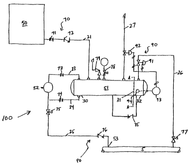
With reference to the Figures, a chemical injection method and system 100 are
described
that enable the introduction of a chemical into a pressurized system 5 at an
injection point 53.
r System l00 includes a chemical storage tank 50 for storing a large volume of
a chemical
to be injected; a higher pressure chemical storage vessel 51 for storing a
smaller and pressurized
volume of the chemical be injected and a control system 90 fox controlling the
flow of low
pressure chemical from the low pressure chemical storage tank 50 to the higher
pressure chemical
storage vessel 51 and from vessel 51 into pressurized system 5 at chemical
injection point 53.
Generally, chemical storage tank 50 is a larger volume, lode pressure tank and
chemical
storage vessel S1 is a smaller volume, high pressure (typically 0-1500psi)
vessel.
Control system 90 includes a pressure valve 91 for opening and closing a
pressure
equalizing line 26 operatively connected to pressurized system 5; a vent valve
92 for opening and
closing a vent 27, and a level sensor 94 for measuring the level of chemical
in vessel 51 and a
micro-controller 93 operatively connected to the level sensor 94 and valves 91
and 92 for
automatic signal processing and valve control.
In addition, the system also includes a first valve system 70 between the
chemical storage
tank 50 and vessel 51 and a second valve system 80 between the higher pressure
vessel 51 and
the pressurized system 5. The valves within the first and second valve systems
may be passive,
manual or automatically operated in accordance with different embodiments of
the invention.
Thus, it is understood that different combinations of valves may be employed
as understood by
those skilled in the art.
The operation of control system 90 along with the other elements of chemical
injection
system 100 is described as follows:
Initial Stage
In the initial stage, prior to filling vessel 51, a volume of chemical is
stored in chemical
storage tank 50. Preferably, a flow valve 71 is closed for preventing the
chemical from entering
CA 02411214 2002-11-06
into chemical storage vessel 51 which remains empty and at atmospheric
pressure during the
initial stage.
Filling Stage
When level sensor 94 determines that vessel 51 is empty a;nd an empty signal
is received
by micro-controller 93, micro-controller 93 closes valve 91 and opens valve 92
to vent 27
allowing vessel 51 to depressurize to atmospheric pressure. Valve 71 is opened
(if previously
closed) and chemical begins to flow under gravity from storage tank 50 to
vessel 51 through line
21 until vessel 51 is filled to an appropriate level.
A passive check valve 72 is preferably located on line 21 for preventing
chemical from
flowing back up line 21 as vessel 51 is pressurized as described below. In
another embodiment,
as shown in Figure 2, valves 71 and 72 may be combined as a single
automatically actuated valve
72' under the control of control system 90.
Injection Stage
When level sensor 94 determines that vessel 51 is full and a full signal is
received by
micro-controller 93, micro-controller 93 closes valve 92 and opens valve 91 to
pressure
equalization line 26, thereby pressurizing vessel 51 until the pressure within
vessel 51 is equal
to the pressure of pressurized system 5. Preferably, line 26 is connected to
pressurized system 5
in order that the pressure inside vessel 51 is the same as the pressurized
system's pressure. As the
pressure in vessel 51 equalizes that of pressurized system 5, the chemical
flow under gravity from
vessel 51 to injection point 53 and into pressurized system 5.
Valve 76 is located along line 25 for preventing the flow of chemical from the
pressurized
system 5 into vessel 51 and for preventing the pressure of pressurized system
5 from pressurizing
vessel 51 when vessel 51_ is being refilled. Valve 76 may be a passive check
valve or a control
valve 76' which may be connected to and controlled by control system 90 as
shown in Figure 2.
The advantage of using passive check valves both upstream and downstream of
the pressure
6
CA 02411214 2002-11-06
vessel 51 is that unless the pressure is equalized between the pressure vessel
side of valve 76 and
the pipeline system side of valve 76, chemical will not flow into pressurized
system 5. Similarly
on the upstream side, chemical will not flow from the storage tank 50 to the
vessel 51 if the
pressure is not equalized on both sides of valve 72.
In one embodiment, a valve 75 is located on line 25 for controlling the rate
of chemical
injection from the vessel 51 into the pressurized system 5. Valve 75 is
preferably a fine control
needle valve. In a further ertlbodiment and as shown in Figure 2, valve 75 may
be combined with
valve 76 as a single automatically actuated valve 76' under the control of
control system 90.
In another embodiment, the rate at which the chemical is being injected into
pressurized
system 5 at chemical injection point 53 can be calculated by incorporating a
rate gauge 52 into
the system 100. Rate gauge 52 is positioned at the same horizontal plane as
vessel 51 and is in
fluid communication with vessel 51 through lines 23 and 24. Rate gauge 52
maintains the same
pressure as vessel 51 and holds a small quantity of chemical. By closing a
valve 73 and a. valve
74, located respectively on lines 23 and 24, chemical will flow from the rate
gauge 52 to the
chemical injection point 53 during the injection stage. By recording the
change in level of
chemical in rate gauge 52 and the amount oftime, the rate of flow can be
calculated.
In another embodiment, vessel 51 includes a weir 31 as best shown in Figure 3.
Vessel
51 receives chemical from line 21 at a first end 30 of vessel 51 and weir 31
is located at a second
end 32 of vessel 51 which is opposite first end 30 of vessel 51. Once the
first end 30 of vessel 51
is nearly full, the chemical will flow over weir 31 between an opening 33
defined by weir 31 and
vessel 51 and fill the second end 32 of vessel 51 containing level sensor 94.
This embodiment
ensures that the first end 30 of vessel 51 is nearly full of chemical before
micro-controller 93
receives a signal that vessel 51 is full and subsequently changes the open or
closed position of
valve 91 or 92. In a further embodiment, each end 30, 32 of vessel 51 are in
fluid communication
through a check valve 25 which allows the chemical to flow from the second end
32 to the first
end 30 of vessel 51 when the first end 30 of vessel 51 is empty.
In another embodiment, several safety valves may be introduced to vessel 51 to
prevent
7
CA 02411214 2002-11-06
potential damage due to over-pressurization. In particular, pressure indicator
78 and pressure
safety valve 79 may be installed respectively for allowing an operator to
observe the pressure
within vessel 51 and for automatically releasing the pressure in vessel 51 if
the pressure in vessel
51 exceeds operational limits. Further, a valve 77 along pressure equalization
line 26 may be used
to govern the rate of pressurization for safety purposes and for maintenance
of the system as is
understood by those skilled in the art.
Refilling Stage
When level sensor 94 determines that vessel S 1 is empty and micro-controller
93 receives
a signal that vessel 51 is empty, micro-controller 93 closes valve 91 and
opens valve 92 to vent
27 for allowing vessel 51 to depressurize to atmospheric pressure for
repeating the filling stage.
Chemical injection system 100 injects a desired amount of chemical into the
pressurized system
by selectively equalizing the pressure between storage tank 50 and vessel 51
and between vessel
51 and pressurized system S without requiring manual operation of the control
or flow valves.
Once the chemical from vessel 51 has been injected into pressurized system 5,
chemical injection
system 100 automatically resets to refill vessel 51 to continue injection into
pressurized system
5.
The repetitive process of injecting and refilling is of benefit to the
petroleum industry as
the process reduces the gas consumption of the system compared to conventional
pumps and
further dramatically reduces the maintenance costs of the subject system as
compared to
conventional pumps.
Application
The system may be implemented in various applications where a chemical is
introduced
into a pressurized syste~rn. As indicated, the system is particularly useful
in the petroleum industry
CA 02411214 2002-11-06
for pressurized pipelines. In addition and due to the automatic control
features of the system,
applications where service personnel or physical size restrictions :prevent or
restrict access of the
system, the invention is particularly advantaged.
9