Language selection

Search

Patent 2411511 Summary

Third-party information liability

Some of the information on this Web page has been provided by external sources. The Government of Canada is not responsible for the accuracy, reliability or currency of the information supplied by external sources. Users wishing to rely upon this information should consult directly with the source of the information. Content provided by external sources is not subject to official languages, privacy and accessibility requirements.

Claims and Abstract availability

Any discrepancies in the text and image of the Claims and Abstract are due to differing posting times. Text of the Claims and Abstract are posted:

  • At the time the application is open to public inspection;
  • At the time of issue of the patent (grant).
(12) Patent Application: (11) CA 2411511
(54) English Title: CONNECTOR BETWEEN TWO STRUCTURAL ELEMENTS
(54) French Title: CONNECTEUR DE LIAISON DE DEUX ELEMENTS DE STRUCTURE
Status: Deemed Abandoned and Beyond the Period of Reinstatement - Pending Response to Notice of Disregarded Communication
Bibliographic Data
(51) International Patent Classification (IPC):
  • F16B 13/04 (2006.01)
  • F16B 5/00 (2006.01)
  • F16B 13/08 (2006.01)
(72) Inventors :
  • HASLER, GEORG (Germany)
(73) Owners :
  • HAFELE GMBH & CO.
(71) Applicants :
  • HAFELE GMBH & CO. (Germany)
(74) Agent: SMART & BIGGAR LP
(74) Associate agent:
(45) Issued:
(22) Filed Date: 2002-11-08
(41) Open to Public Inspection: 2003-05-09
Availability of licence: N/A
Dedicated to the Public: N/A
(25) Language of filing: English

Patent Cooperation Treaty (PCT): No

(30) Application Priority Data:
Application No. Country/Territory Date
201 18279.3 (Germany) 2001-11-09

Abstracts

English Abstract


In order to create a connector between two structural elements 10, 12, in
particular panels; which comprises a bolt 5 that is supported in a sleeve 1
that consists of an upper section 2 and a lower section 3, the lower section 3
of the sleeve together with the rear end 7 of the bolt fitting into a recess 9
in
the first structural element 10, and the upper section 2 of the sleeve
together with the front end 5 of the bolt fitting into a recess 11 in the
second
structural element, and the bolt head 6 working in conjunction with a holding
or gripping device that is arranged in the second structural element 12, and
which can be used regardless of the type of installation, there is one or a
plurality of bars 14 arranged on the part of the upper section 2 of the sleeve
that is adjacent to the lower section 3 of the sleeve, said bars extending
obliquely outward towards the lower section 3 of the sleeve and pivoting
toward the sleeve 1.


Claims

Note: Claims are shown in the official language in which they were submitted.

Patent Claims
1. Connector between two structural elements (10, 12), in particular
panels, with a bolt (5) that is held in a sleeve (1) comprising an upper
(2) and lower section (3), the lower section (3) of the sleeve together
with the rear end (7) of the bolt fitting in a recess (9) in the first
structural element (10), and the upper section (2) of the sleeve with
the front end (5) of the bolt fitting into a recess (11) of the second
structural element (12), the bolt head (6) working in conjunction with
a holding or gripping device installed in the second structural element
(12), characterized in that in the part of the upper section (2) of the
sleeve that is adjacent to the tower section (3) of the sleeve there is
one or a plurality of pivotable bars (14) that extend obliquely outward
towards the lower section (3) of the sleeve and can pivot towards the
sleeve (1).
2. Connector as defined in Claim 1, characterized in that the unattached
ends of the bars (14) are configured as stops for the depth to which
the lower section (3) of the sleeve penetrates into its recess (9).
7

3. Connector as defined in one or both of the preceding claims,
characterized in that the struts (14) can pivot into slots (15) in the
upper section (2) of the sleeve.
4. Connector as defined in one or more of the preceding claims,
characterized in that the bars (14) are of the same material as the
sleeve (1).
5. Connector as defined in one of more of the preceding claims,
characterized in that the bars (14) are of elastic material.
6. Connector as defined in one or more of the preceding claims,
characterized in that the lower section (3) of the sleeve has barb-like
annular ribs (16) around its outer periphery.
7. Connector as defined in one or more of the preceding claims,
characterized in that the upper section (2) of the sleeve is provided
with longitudinal guide ribs (17).
8

Description

Note: Descriptions are shown in the official language in which they were submitted.


CA 02411511 2002-11-08
Connector Between Two Structural Elements
The present invention relates to a connector between two structural
elements, in particular panels for furniture, with a bolt that is accommodated
in a sleeve consisting of an upper and a lower section, the lower part of said
sleeve together with the rear end of the bolt fitting in a recess in the first
structural element, and the upper section of the sleeve together with the
front end of the bolt fitting in a recess in the second structural element,
the
head of the bolt working in conjunction with a holding or gripping device that
is arranged in the second structural element. In connections that are only
subjected to light stresses, it is sufficient if the lower section of the
sleeve is
held in its recess by barb-like elements. In this case, the bolt is fixed, on
the
one hand, in the lower section of the sleeve and, on the other hand, with its
head in a holding device in the second structural element. In most
instances, however, the connections are severely stressed and the lower
section of the sleeve must be securely anchored. Then, an expansion bolt is
used, and this is displaced axially by means of a gripping device. When this
is done, the lower, conically configured end of the bolt spreads the lower
part of the sleeve apart and presses it against the walls of the recess.
1

CA 02411511 2002-11-08
In order to join the two structural elements, the recesses are first bored and
the holding or gripping device is inserted. Then, either the lower section of
the sleeve or the upper section of the sleeve is first inserted into the
appropriate recesses in the particular structural element. Next; the other
structural element is positioned, in that the recess in this element is slid
onto
the other section of the sleeve. In order to ensure that the head of the bolt
can always engage in the holding or gripping device, it should be ensured
that the bore depth of the recesses, at least for the lower section of the
sleeve, does not exceed a specific size. In practice, however, it is not
always
possible to avoid bores that are too deep; so that in order to ensure precise
positioning of the sleeve in its recesses there is an annular stop between the
upper and lower sections of the sleeve, so that the lower section of the
sleeve is always prevented from being inserted to too great a depth. If,
however, installation is to be such that the bolt head is first inserted into
the
holding or gripping device and this recess has been bored so that it is too
deep, this annular stop shoulder prevents insertion of the bolt head into the
holding or gripping device, so that a sleeve without a stop must be used in
such a case.
It is the objective of the present invention to create a connector of the type
described above that can be used regardless of the type of installation that
is
2

CA 02411511 2002-11-08
involved: According to the present invention, this objective has been
achieved in that one or a plurality of bars that extend obliquely outwards
towards the lower section of the sleeve and which can pivot relative to the
sleeve are arranged on that part of the upper section of the sleeve that
adjoins the lower section of the sleeve. The lower section of the sleeve is
inserted initially, the projecting bars act as a stop on the structural
element,
so that the lower section of the sleeve is supported within the corresponding
structural element in a position that is always the same. When the second
structural element is set in position, the bars will of necessity be pivoted
towards the sleeve by the walls of the recess, so that the stop effect is
cancelled.
In contrast to this, if the upper section of the slee a is inserted first,
with the
bolt head being inserted into the holding or gripping device, these bars wilt
similarly be pivoted towards the sleeve. Once again, the stop effect is
cancelled, and one can position the lower section of the sleeve regardless of
the depth of the recess in the other structural element.
It is true that, generally speaking, pressing the bars against the sleeve will
be enough to cancel out the stop effect; although this can be achieved with
3

CA 02411511 2002-11-08
absolute certainty if the bars can pivot into slots in the upper section of
the
sleeve, when they are then flush with he surface of the sleeve.
It is preferred that the bars be of the same material as the sleeve. If the
bars are molded from an elastic material, there is no need for special joints,
such as film-type hinges, in order to ensure that the bars can pivot. In the
manner known per se the outer periphery of the lower section of the sleeve
is provided with barb-like annular ribs, and the upper section of the sleeve
incorporates longitudinal guide or standoff ribs.
The present invention will be described in greater detail below on the basis
of the drawings appended hereto. These drawings show the following:
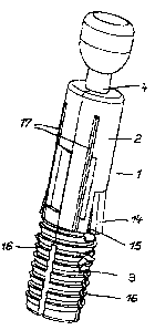
I=figure 1: a perspective view of a connector;
Figure 2: a cross section through a connecting inserted into a first
structural element;
Figure 3: a view as in Figure 2, with-the second structural element
installed.
The sleeve 1 consists of the upper section 2 of the sleeve and the lower
section 3 of the sleeve, there being a bolt 4 that can be displaced
4

CA 02411511 2002-11-08
longitudinally within the sleeve 1. At the front end of the bolt 5 there is a
bolt head 6, and there is an expansion cone at the rear end 7 of the bolt.
The lower section 3 of the cone that incorporates the barb-like annular rings
16 is configured as an extension sleeve and is inserted into a first recess 9
in
the first structural element 10 (Figure 2): In contrast to this, tha bolt head
6
of the upper section 2 of the sleeve with the longitudinal guide ribs 17 fits
in
a recess 11 in the second structural element 12 (Figure 3). Within this
structural element 12, there is a gripping device (not shown herein) by
means of which the bolt head 6 and thus the bolt 5 can be displaced in the
direction indicated by the arrow 13. When this takes place, the tower section
3 of the sleeve that is configured as an expansion sleeve will be pressed
against the walls of the recess 9 by the expansion cone 8 of the bolt 5, so
that it is securely held.
The upper section 2 of the sleeve is provided with elastically pivotable. bars
14 that are directed obliquely outward towards the tower section 3 of the
sleeve; these bars can pivot inward into slots 15 in the upper section 2 of
the sleeve. As can be seen in Figure 2, the depth to which the lower section
3 of the sleeve penetrates into the first structural element 10 is limited by
the unattached ends of the bars 14, which act as stops. As soon as the

CA 02411511 2002-11-08
recess 11 of the second structural element 12 is slid onto the sleeve 2, the
bars 14 pivot into the slots 15; so that the stop effect is cancelled.
If installation is effected in the reverse order, when the bolt head 6 of the
upper section 2 of the sleeve is first inserted into the recess 11 in the
second
structural element 12, the bars 14 will similarly be pivoted into the slots 15
and thus have no effect as stops. Thus, it is ensured that the bolt head 6
can be inserted into the holding or gripping device (not shown herein). Only
then is recess 9 of the first structural slid onto the lower section 3 of the
sleeve, tha bolt 5 tightened, and the sleeve 3 expanded .
6

Representative Drawing
A single figure which represents the drawing illustrating the invention.
Administrative Status

2024-08-01:As part of the Next Generation Patents (NGP) transition, the Canadian Patents Database (CPD) now contains a more detailed Event History, which replicates the Event Log of our new back-office solution.

Please note that "Inactive:" events refers to events no longer in use in our new back-office solution.

For a clearer understanding of the status of the application/patent presented on this page, the site Disclaimer , as well as the definitions for Patent , Event History , Maintenance Fee  and Payment History  should be consulted.

Event History

Description Date
Application Not Reinstated by Deadline 2007-11-08
Time Limit for Reversal Expired 2007-11-08
Deemed Abandoned - Failure to Respond to Maintenance Fee Notice 2006-11-08
Inactive: IPC from MCD 2006-03-12
Application Published (Open to Public Inspection) 2003-05-09
Inactive: Cover page published 2003-05-08
Inactive: First IPC assigned 2003-01-23
Letter Sent 2003-01-20
Application Received - Regular National 2003-01-08
Filing Requirements Determined Compliant 2003-01-08
Inactive: Filing certificate - No RFE (English) 2003-01-08

Abandonment History

Abandonment Date Reason Reinstatement Date
2006-11-08

Maintenance Fee

The last payment was received on 2005-10-07

Note : If the full payment has not been received on or before the date indicated, a further fee may be required which may be one of the following

  • the reinstatement fee;
  • the late payment fee; or
  • additional fee to reverse deemed expiry.

Please refer to the CIPO Patent Fees web page to see all current fee amounts.

Fee History

Fee Type Anniversary Year Due Date Paid Date
Application fee - standard 2002-11-08
Registration of a document 2002-11-28
MF (application, 2nd anniv.) - standard 02 2004-11-08 2004-09-16
MF (application, 3rd anniv.) - standard 03 2005-11-08 2005-10-07
Owners on Record

Note: Records showing the ownership history in alphabetical order.

Current Owners on Record
HAFELE GMBH & CO.
Past Owners on Record
GEORG HASLER
Past Owners that do not appear in the "Owners on Record" listing will appear in other documentation within the application.
Documents

To view selected files, please enter reCAPTCHA code :


To view images, click a link in the Document Description column. To download the documents, select one or more checkboxes in the first column and then click the "Download Selected in PDF format (Zip Archive)" or the "Download Selected as Single PDF" button.

List of published and non-published patent-specific documents on the CPD .

If you have any difficulty accessing content, you can call the Client Service Centre at 1-866-997-1936 or send them an e-mail at CIPO Client Service Centre.


Document
Description 
Date
(yyyy-mm-dd) 
Number of pages   Size of Image (KB) 
Abstract 2002-11-08 1 31
Description 2002-11-08 6 224
Claims 2002-11-08 2 62
Drawings 2002-11-08 3 80
Representative drawing 2003-01-28 1 8
Cover Page 2003-04-22 1 40
Filing Certificate (English) 2003-01-08 1 159
Courtesy - Certificate of registration (related document(s)) 2003-01-20 1 107
Reminder of maintenance fee due 2004-07-12 1 110
Courtesy - Abandonment Letter (Maintenance Fee) 2007-01-03 1 175
Reminder - Request for Examination 2007-07-10 1 119