Sélection de la langue

Search

Sommaire du brevet 2411511 

Énoncé de désistement de responsabilité concernant l'information provenant de tiers

Une partie des informations de ce site Web a été fournie par des sources externes. Le gouvernement du Canada n'assume aucune responsabilité concernant la précision, l'actualité ou la fiabilité des informations fournies par les sources externes. Les utilisateurs qui désirent employer cette information devraient consulter directement la source des informations. Le contenu fourni par les sources externes n'est pas assujetti aux exigences sur les langues officielles, la protection des renseignements personnels et l'accessibilité.

Disponibilité de l'Abrégé et des Revendications

L'apparition de différences dans le texte et l'image des Revendications et de l'Abrégé dépend du moment auquel le document est publié. Les textes des Revendications et de l'Abrégé sont affichés :

  • lorsque la demande peut être examinée par le public;
  • lorsque le brevet est émis (délivrance).
(12) Demande de brevet: (11) CA 2411511
(54) Titre français: CONNECTEUR DE LIAISON DE DEUX ELEMENTS DE STRUCTURE
(54) Titre anglais: CONNECTOR BETWEEN TWO STRUCTURAL ELEMENTS
Statut: Réputée abandonnée et au-delà du délai pour le rétablissement - en attente de la réponse à l’avis de communication rejetée
Données bibliographiques
(51) Classification internationale des brevets (CIB):
  • F16B 13/04 (2006.01)
  • F16B 5/00 (2006.01)
  • F16B 13/08 (2006.01)
(72) Inventeurs :
  • HASLER, GEORG (Allemagne)
(73) Titulaires :
  • HAFELE GMBH & CO.
(71) Demandeurs :
  • HAFELE GMBH & CO. (Allemagne)
(74) Agent: SMART & BIGGAR LP
(74) Co-agent:
(45) Délivré:
(22) Date de dépôt: 2002-11-08
(41) Mise à la disponibilité du public: 2003-05-09
Licence disponible: S.O.
Cédé au domaine public: S.O.
(25) Langue des documents déposés: Anglais

Traité de coopération en matière de brevets (PCT): Non

(30) Données de priorité de la demande:
Numéro de la demande Pays / territoire Date
201 18279.3 (Allemagne) 2001-11-09

Abrégés

Abrégé anglais


In order to create a connector between two structural elements 10, 12, in
particular panels; which comprises a bolt 5 that is supported in a sleeve 1
that consists of an upper section 2 and a lower section 3, the lower section 3
of the sleeve together with the rear end 7 of the bolt fitting into a recess 9
in
the first structural element 10, and the upper section 2 of the sleeve
together with the front end 5 of the bolt fitting into a recess 11 in the
second
structural element, and the bolt head 6 working in conjunction with a holding
or gripping device that is arranged in the second structural element 12, and
which can be used regardless of the type of installation, there is one or a
plurality of bars 14 arranged on the part of the upper section 2 of the sleeve
that is adjacent to the lower section 3 of the sleeve, said bars extending
obliquely outward towards the lower section 3 of the sleeve and pivoting
toward the sleeve 1.

Revendications

Note : Les revendications sont présentées dans la langue officielle dans laquelle elles ont été soumises.


Patent Claims
1. Connector between two structural elements (10, 12), in particular
panels, with a bolt (5) that is held in a sleeve (1) comprising an upper
(2) and lower section (3), the lower section (3) of the sleeve together
with the rear end (7) of the bolt fitting in a recess (9) in the first
structural element (10), and the upper section (2) of the sleeve with
the front end (5) of the bolt fitting into a recess (11) of the second
structural element (12), the bolt head (6) working in conjunction with
a holding or gripping device installed in the second structural element
(12), characterized in that in the part of the upper section (2) of the
sleeve that is adjacent to the tower section (3) of the sleeve there is
one or a plurality of pivotable bars (14) that extend obliquely outward
towards the lower section (3) of the sleeve and can pivot towards the
sleeve (1).
2. Connector as defined in Claim 1, characterized in that the unattached
ends of the bars (14) are configured as stops for the depth to which
the lower section (3) of the sleeve penetrates into its recess (9).
7

3. Connector as defined in one or both of the preceding claims,
characterized in that the struts (14) can pivot into slots (15) in the
upper section (2) of the sleeve.
4. Connector as defined in one or more of the preceding claims,
characterized in that the bars (14) are of the same material as the
sleeve (1).
5. Connector as defined in one of more of the preceding claims,
characterized in that the bars (14) are of elastic material.
6. Connector as defined in one or more of the preceding claims,
characterized in that the lower section (3) of the sleeve has barb-like
annular ribs (16) around its outer periphery.
7. Connector as defined in one or more of the preceding claims,
characterized in that the upper section (2) of the sleeve is provided
with longitudinal guide ribs (17).
8

Description

Note : Les descriptions sont présentées dans la langue officielle dans laquelle elles ont été soumises.

CA 02411511 2002-11-08
Connector Between Two Structural Elements
The present invention relates to a connector between two structural
elements, in particular panels for furniture, with a bolt that is accommodated
in a sleeve consisting of an upper and a lower section, the lower part of said
sleeve together with the rear end of the bolt fitting in a recess in the first
structural element, and the upper section of the sleeve together with the
front end of the bolt fitting in a recess in the second structural element,
the
head of the bolt working in conjunction with a holding or gripping device that
is arranged in the second structural element. In connections that are only
subjected to light stresses, it is sufficient if the lower section of the
sleeve is
held in its recess by barb-like elements. In this case, the bolt is fixed, on
the
one hand, in the lower section of the sleeve and, on the other hand, with its
head in a holding device in the second structural element. In most
instances, however, the connections are severely stressed and the lower
section of the sleeve must be securely anchored. Then, an expansion bolt is
used, and this is displaced axially by means of a gripping device. When this
is done, the lower, conically configured end of the bolt spreads the lower
part of the sleeve apart and presses it against the walls of the recess.
1

CA 02411511 2002-11-08
In order to join the two structural elements, the recesses are first bored and
the holding or gripping device is inserted. Then, either the lower section of
the sleeve or the upper section of the sleeve is first inserted into the
appropriate recesses in the particular structural element. Next; the other
structural element is positioned, in that the recess in this element is slid
onto
the other section of the sleeve. In order to ensure that the head of the bolt
can always engage in the holding or gripping device, it should be ensured
that the bore depth of the recesses, at least for the lower section of the
sleeve, does not exceed a specific size. In practice, however, it is not
always
possible to avoid bores that are too deep; so that in order to ensure precise
positioning of the sleeve in its recesses there is an annular stop between the
upper and lower sections of the sleeve, so that the lower section of the
sleeve is always prevented from being inserted to too great a depth. If,
however, installation is to be such that the bolt head is first inserted into
the
holding or gripping device and this recess has been bored so that it is too
deep, this annular stop shoulder prevents insertion of the bolt head into the
holding or gripping device, so that a sleeve without a stop must be used in
such a case.
It is the objective of the present invention to create a connector of the type
described above that can be used regardless of the type of installation that
is
2

CA 02411511 2002-11-08
involved: According to the present invention, this objective has been
achieved in that one or a plurality of bars that extend obliquely outwards
towards the lower section of the sleeve and which can pivot relative to the
sleeve are arranged on that part of the upper section of the sleeve that
adjoins the lower section of the sleeve. The lower section of the sleeve is
inserted initially, the projecting bars act as a stop on the structural
element,
so that the lower section of the sleeve is supported within the corresponding
structural element in a position that is always the same. When the second
structural element is set in position, the bars will of necessity be pivoted
towards the sleeve by the walls of the recess, so that the stop effect is
cancelled.
In contrast to this, if the upper section of the slee a is inserted first,
with the
bolt head being inserted into the holding or gripping device, these bars wilt
similarly be pivoted towards the sleeve. Once again, the stop effect is
cancelled, and one can position the lower section of the sleeve regardless of
the depth of the recess in the other structural element.
It is true that, generally speaking, pressing the bars against the sleeve will
be enough to cancel out the stop effect; although this can be achieved with
3

CA 02411511 2002-11-08
absolute certainty if the bars can pivot into slots in the upper section of
the
sleeve, when they are then flush with he surface of the sleeve.
It is preferred that the bars be of the same material as the sleeve. If the
bars are molded from an elastic material, there is no need for special joints,
such as film-type hinges, in order to ensure that the bars can pivot. In the
manner known per se the outer periphery of the lower section of the sleeve
is provided with barb-like annular ribs, and the upper section of the sleeve
incorporates longitudinal guide or standoff ribs.
The present invention will be described in greater detail below on the basis
of the drawings appended hereto. These drawings show the following:
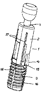
I=figure 1: a perspective view of a connector;
Figure 2: a cross section through a connecting inserted into a first
structural element;
Figure 3: a view as in Figure 2, with-the second structural element
installed.
The sleeve 1 consists of the upper section 2 of the sleeve and the lower
section 3 of the sleeve, there being a bolt 4 that can be displaced
4

CA 02411511 2002-11-08
longitudinally within the sleeve 1. At the front end of the bolt 5 there is a
bolt head 6, and there is an expansion cone at the rear end 7 of the bolt.
The lower section 3 of the cone that incorporates the barb-like annular rings
16 is configured as an extension sleeve and is inserted into a first recess 9
in
the first structural element 10 (Figure 2): In contrast to this, tha bolt head
6
of the upper section 2 of the sleeve with the longitudinal guide ribs 17 fits
in
a recess 11 in the second structural element 12 (Figure 3). Within this
structural element 12, there is a gripping device (not shown herein) by
means of which the bolt head 6 and thus the bolt 5 can be displaced in the
direction indicated by the arrow 13. When this takes place, the tower section
3 of the sleeve that is configured as an expansion sleeve will be pressed
against the walls of the recess 9 by the expansion cone 8 of the bolt 5, so
that it is securely held.
The upper section 2 of the sleeve is provided with elastically pivotable. bars
14 that are directed obliquely outward towards the tower section 3 of the
sleeve; these bars can pivot inward into slots 15 in the upper section 2 of
the sleeve. As can be seen in Figure 2, the depth to which the lower section
3 of the sleeve penetrates into the first structural element 10 is limited by
the unattached ends of the bars 14, which act as stops. As soon as the

CA 02411511 2002-11-08
recess 11 of the second structural element 12 is slid onto the sleeve 2, the
bars 14 pivot into the slots 15; so that the stop effect is cancelled.
If installation is effected in the reverse order, when the bolt head 6 of the
upper section 2 of the sleeve is first inserted into the recess 11 in the
second
structural element 12, the bars 14 will similarly be pivoted into the slots 15
and thus have no effect as stops. Thus, it is ensured that the bolt head 6
can be inserted into the holding or gripping device (not shown herein). Only
then is recess 9 of the first structural slid onto the lower section 3 of the
sleeve, tha bolt 5 tightened, and the sleeve 3 expanded .
6

Dessin représentatif
Une figure unique qui représente un dessin illustrant l'invention.
États administratifs

2024-08-01 : Dans le cadre de la transition vers les Brevets de nouvelle génération (BNG), la base de données sur les brevets canadiens (BDBC) contient désormais un Historique d'événement plus détaillé, qui reproduit le Journal des événements de notre nouvelle solution interne.

Veuillez noter que les événements débutant par « Inactive : » se réfèrent à des événements qui ne sont plus utilisés dans notre nouvelle solution interne.

Pour une meilleure compréhension de l'état de la demande ou brevet qui figure sur cette page, la rubrique Mise en garde , et les descriptions de Brevet , Historique d'événement , Taxes périodiques et Historique des paiements devraient être consultées.

Historique d'événement

Description Date
Demande non rétablie avant l'échéance 2007-11-08
Le délai pour l'annulation est expiré 2007-11-08
Réputée abandonnée - omission de répondre à un avis sur les taxes pour le maintien en état 2006-11-08
Inactive : CIB de MCD 2006-03-12
Demande publiée (accessible au public) 2003-05-09
Inactive : Page couverture publiée 2003-05-08
Inactive : CIB en 1re position 2003-01-23
Lettre envoyée 2003-01-20
Demande reçue - nationale ordinaire 2003-01-08
Exigences de dépôt - jugé conforme 2003-01-08
Inactive : Certificat de dépôt - Sans RE (Anglais) 2003-01-08

Historique d'abandonnement

Date d'abandonnement Raison Date de rétablissement
2006-11-08

Taxes périodiques

Le dernier paiement a été reçu le 2005-10-07

Avis : Si le paiement en totalité n'a pas été reçu au plus tard à la date indiquée, une taxe supplémentaire peut être imposée, soit une des taxes suivantes :

  • taxe de rétablissement ;
  • taxe pour paiement en souffrance ; ou
  • taxe additionnelle pour le renversement d'une péremption réputée.

Veuillez vous référer à la page web des taxes sur les brevets de l'OPIC pour voir tous les montants actuels des taxes.

Historique des taxes

Type de taxes Anniversaire Échéance Date payée
Taxe pour le dépôt - générale 2002-11-08
Enregistrement d'un document 2002-11-28
TM (demande, 2e anniv.) - générale 02 2004-11-08 2004-09-16
TM (demande, 3e anniv.) - générale 03 2005-11-08 2005-10-07
Titulaires au dossier

Les titulaires actuels et antérieures au dossier sont affichés en ordre alphabétique.

Titulaires actuels au dossier
HAFELE GMBH & CO.
Titulaires antérieures au dossier
GEORG HASLER
Les propriétaires antérieurs qui ne figurent pas dans la liste des « Propriétaires au dossier » apparaîtront dans d'autres documents au dossier.
Documents

Pour visionner les fichiers sélectionnés, entrer le code reCAPTCHA :


Pour visualiser une image, cliquer sur un lien dans la colonne description du document. Pour télécharger l'image (les images), cliquer l'une ou plusieurs cases à cocher dans la première colonne et ensuite cliquer sur le bouton "Télécharger sélection en format PDF (archive Zip)" ou le bouton "Télécharger sélection (en un fichier PDF fusionné)".

Liste des documents de brevet publiés et non publiés sur la BDBC .

Si vous avez des difficultés à accéder au contenu, veuillez communiquer avec le Centre de services à la clientèle au 1-866-997-1936, ou envoyer un courriel au Centre de service à la clientèle de l'OPIC.


Description du
Document 
Date
(aaaa-mm-jj) 
Nombre de pages   Taille de l'image (Ko) 
Abrégé 2002-11-08 1 31
Description 2002-11-08 6 224
Revendications 2002-11-08 2 62
Dessins 2002-11-08 3 80
Dessin représentatif 2003-01-28 1 8
Page couverture 2003-04-22 1 40
Certificat de dépôt (anglais) 2003-01-08 1 159
Courtoisie - Certificat d'enregistrement (document(s) connexe(s)) 2003-01-20 1 107
Rappel de taxe de maintien due 2004-07-12 1 110
Courtoisie - Lettre d'abandon (taxe de maintien en état) 2007-01-03 1 175
Rappel - requête d'examen 2007-07-10 1 119