Note: Descriptions are shown in the official language in which they were submitted.
CA 02411620 2002-11-08
Attorney Docket 3810.18
REEL SPOOL AND STAND ASSEMBLY FOR
COILED TUBING INJECTOR SYSTEM
FIELD OF INVENTION
The invention pertains generally to coiled tubing reels used in conjunction
with coiled
tubing injectors for performing well servicing and coiled tubing drilling
operations.
BACKGROUND OF THE INVENTION
Continuous pipe, generally known within the industry as coiled tubing since it
is stored
on a large reel, has been used for many years. It is much faster to run into
and out of a well
bore than conventional jointed straight pipe since there is no need to join or
disconnect short
segments of straight pipe.
Coiled tubing "injectors" are machines that are used to run continuous strings
of pipe into
and out of well bores. The injector is normally mounted to an elevated
platform above a
wellhead or is mounted directly on top of a wellhead. A typical coiled tubing
injector has two
continuous chains. The chains are mounted on sprockets to form two elongated
loops that
counter rotate. The chains are placed next to each other in an opposing
fashion. Tubing is fed
between the chains. Grippers carried by each chain come together on opposite
sides of the
pipe and are pressed against it. The injector thereby continuously grips a
length of the tubing
as it is being moved in and out of the well bore. Examples of coiled tubing
injectors include
those shown and described in U.S. Patent No. 5,309,900.
A coiled tubing reel assembly includes a stand for supporting a spool on which
tubing is
stored, a drive system for rotating the reel and creating back-tension during
operation of the
reel, and a "level winding" system that guides the tubing as it is being
unwound from and wound
onto the spool. The level winding system moves the tubing laterally across the
reel so that the
tubing is laid across the reel in a neat and organized fashion. The coiled
tubing reel assembly
must rotate the spool to feed tubing to and from the injector and well bore.
The tubing reel
assembly must also tension the tubing by always pulling against the injector
during normal
operation. The injector must pull against the tension to take the tubing from
the tubing reel, and
the reel must have sufficient pulling force and speed to keep up with the
injector and maintain
tension on the tubing as the tubing is being pulled out of the well bore by
the injector. The
tension on the tubing must always be maintained. The tension must also be
sufficient to wind
1
CA 02411620 2002-11-08
Attorney Docket 3810.18
properly the tubing on the spool and to keep the tubing wound on the spool.
Consequently, a
coiled tubing reel assembly is subject to substantial forces and loads.
Tubing reel assemblies are typically transported to wells with the required
coiled tubing
wound on the spool, and the spool installed in the reel assembly. Such spools
are specially
designed for the particular reel assembly and not meant to be disconnected or
removed from
the reel assembly during normal operation. A second reel assembly would
therefore also have
to be sent if there was need for a different diameter tubing or in the event
that replacement
tubing was required. Alternately, if replacement tubing was required, a
shipping spool could be
used to transport replacement tubing to the well. A lightweight spooling stand
would then have
to be used to support the shipping spool to transfer the tubing onto the spool
of the working reel
assembly. To save weight and size, these shipping spools do not possess the
structure
necessary to handle the loads typically imposed on reels during coiled tubing
operations.
Rather, shipping spools are designed as a relatively inexpensive means of
transporting the
tubing from a factory to a well. Therefore, transferring tubing from the
shipping spool to the
working reel assembly is necessary.
Transferring tubing from a shipping spool to a working reel induces extra
strain in the
tubing as it is unwound from the shipping spool then rewound onto the working
spool. Since
metal tubing is plastically deformed during spooling, transferring coiled
tubing from a shipping
spool to a working reel assembly reduces the life or number of hours that the
tubing can be
used, thus increasing the cost of coiled tubing operations. Furthermore,
transfers typically
involve spooling 20,000 to 25,000 feet of tubing at rates of 100 to 200 feet
per minute.
Therefore, considerable time is required to complete a transfer.
There exist coiled tubing reel stands for receiving common and ordinary
shipping spools
for use as working reels. These tubing reel assemblies require inserting a
shaft through the
center of the spool, and inserting a pair of driving knobs, mounted to a drive
plate on the stand,
into the side of the spool to provide the connection for the drive system. As
a consequence, this
type of reel stand has several problems. First, the reel stand either has to
be separable into two
halves so that the sides of the stand can be moved laterally away from each
other, or has to
have the sides of the stand capable of being swung outwardly, in order to
allow the shipping
spool of tubing to be loaded on the stand. Second, the spool has to be
carefully aligned with the
drive system on the stand. Spools wound with tubing are very large and heavy,
weighing
30,000 to 60,000 lbs. on average. They are cumbersome and difficult to
maneuver.
Consequently, aligning a spool and the drive system on a rocking ship or in
high winds is a
2
CA 02411620 2002-11-08
Attorney Docket 3810.18
difficult task. Third, as previously mentioned, standard and ordinary shipping
spools are not
built to handle the substantial loads encountered by a typical working spool.
SUMMARY OF THE INVENTION
Many of these problems are addressed by using a working spool that is
removably
mounted to a stand. The spool is supported on a stand by a pair of axles. A
drive coupling,
which is preferably formed when the spool is lowered onto the stand, transmits
rotational motion
to the spool. However, such a spool and stand assembly can be subject to
several problems,
one of which is caused by the fact that fluid used in drilling and workover
operations is supplied
to the coiled tubing under very high pressure. Passing the fluid through a
bore created in an
axle stresses the axle and a hub or other structure to which the axle is
connected. To solve this
problem, coiled tubing on a removable spool is coupled to a fluid source by a
fluid conduit that
extends through a bore in the axle. Stress created by the fluid pressure is
not transferred to the
axle and the structure supporting the axle, thereby avoiding having to
reinforce the structure to
which the axle is connected.
It is preferred that a relatively short fluid conduit, which will be referred
to as a pipe, is
passed through a bore in one of the two axles to connect the coiled tubing on
the spool to a fluid
source. The pipe is withdrawn at least far enough to provide enough clearance
to allow the
spool to be loaded onto the stand, and then extended so that it extends across
a coupling of the
spool to the stand. A swivel joint is coupled to one of the pipe's two ends.
If one side of the
swivel joint is coupled to the end of the pipe that is inside of the spool,
the other side of the
swivel joint is coupled to the coiled tubing, and the end of the pipe outside
the stand is coupled
to the fluid source. In this configuration, the pipe remains stationary with
respect to the stand
when the spool rotates. If the swivel joint is coupled to the end of the pipe
outside the spool, the
coiled tubing is coupled to the opposite end of the pipe and the fluid source
is then coupled to
the swivel joint opposite the pipe. The pipe rotates with the spool when the
swivel joint is
mounted outside the spool. If desired, the swivel joint may be permitted to be
attached at either
end of the pipe, giving the option of having the swivel joint placed either
inside the spool or
outside the stand.
3
CA 02411620 2008-11-19
Certain exemplary embodiments may provide a reel assembly for supplying
continuous pipe of a type used in oilfield service operations, comprising: a
stand onto
which a spoof of continuous pipe is lowered; a drive coupling for transmitting
rotational
power from the stand to the spool; an axle for supporting the spool on the
stand and
disposed for rotation with the spool; a pipe slidably disposed within a bore
formed
through the axle for communicating fluid between the continuous tubing wound
on the
spool and a fluid source, whereby the pipe is retracted to provide clearance
for lowering
the spool onto the stand, and is extended after lowering the spool onto the
stand, with a
first end of the pipe disposed inside such spool and an opposite, second end
of the pipe
disposed outside the stand when extended.
Certain other exemplary embodiments may provide a stand for supporting a
spoof wound with continuous pipe of a type used in oilfield service
operations,
comprising: a structure supporting a drive coupling member for transmitting
rotational
power and a pair of axles; and a pipe slidably disposed within a bore formed
through one
of the pair of axles for communicating fluid, whereby the pipe may be placed
in a
retracted position and an extended position with respect to the one of the
pair of axles.
Yet another exemplary embodiment may provide a method in which a spool
wound with continuous pipe for well-related operations is lowered onto a
stand, the spool
being supported on the stand by at least one axle and receiving rotational
power through
a coupling between the spool and stand, the method comprising: withdrawing at
least
partially a pipe from a bore formed in the at least one axle when lowering the
spool onto
or removing it from, the stand so that the pipe does not interfere with
lowering or
removing the pipe from the stand; extending that pipe through the bore when
the spool is
mounted on the stand so that a first end of the pipe is disposed inside the
spool and a
second end of the pipe is disposed outside the spool; and coupling either the
first or the
second end of the pipe to a swivel joint.
3a
CA 02411620 2002-11-08
Attorney Docket 3810.18
BRIEF DESCRIPTION OF THE DRAWINGS
FIG. 1A is a side view of a reel assembly, including a spool and stand
combination, for a
coiled tubing injector.
FIG. I B is an end view of the reel assembly of FIG. 1 A.
FIG. 2 is a perspective view of a spool for coiled tubing.
FIG. 3 is a sectioned end view of the reel assembly of FIG. 1A.
FIG. 4A is a plan view of a catch mounted inside the spool of FIG. 2.
FIG. 4B is a side view of the catch of FIG. 4A.
FIG. 5 is a section through a portion of the reel assembly of FIGS 1A and 1 B
in a second
configuration.
FIG. 6 is a section through a portion of the reel assembly of FIGS 1A and 1B
in a first
configuration.
FIG. 7 is a side view of the stand of the reel assembly of FIGS. 1A and 1B.
FIG. 8 is a plan view of a bracket in an open position for holding a swivel
joint in the
center of a coiled tubing spool.
FIG. 9 is a side view of the bracket of FIG. 8 in a closed position, with the
swivel joint
installed.
FIG. 10 is a plan view of the closed bracket of FIG. 9.
DETAILED DESCRIPTION OF DRAWINGS
In the following description of a preferred embodiment, like reference numbers
refer to
like parts.
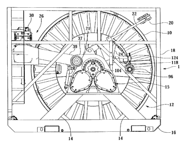
Referring to FIGS. 1A, 1B and 7, tubing reel assembly 1 includes coiled tubing
spool 10.
Coiled tubing 11 is wound on the spool. The spool is mounted for rotation on a
stand that is
generally designated as 12. The stand also imparts rotational motion to the
spool through a
drive coupling. The stand may be of any configuration. The illustrated stand
is intended to be
representative only. In the illustrated embodiment, the stand includes legs 14
and a gear
housing 15. Inside each gear housing is a transmission that transfers
rotational power from one
of two motors 36 (only one visible) to one half of drive coupling 40. The
stand also supports a
4
CA 02411620 2002-11-08
Attorney Docket 3810.18
pair of axles, which are not visible in these views. An "axle" refers to a
supporting member that
carries a spool, and that either rotates with the spool to transmit power to
it or allows the spool
to rotate freely on it. It can take the form of a pin, shaft, bar, beam or
spindle, for example. The
axies support the spool as it rotates. The axles may instead be mounted on
spool 10 rather than
the stand. It is preferred to mount the stand on skids 16 so that it can be
easily transported. A
removable cage frame 18 protects the stand and spool, but is open at the top
to allow the spool
to be lowered onto the stand. A spreader bar 20 for hoisting the stand and for
raising and
lowering the spool onto the stand is shown attached to the top of stand 12 at
eyelets 21. The
legs 22 of the spreader bar pivot to allow the bar to be moved out of the way
during operation of
reel assembly. Each leg is supported by an arm 24, which is attached to the
leg by means of a
sliding clamp.
A level winding mechanism 26 is also pivotally attached to the stand through a
pair of
support arms 39. Hydraulic cylinder 28 supports and pivots the arm of the
level wind
mechanism. Level wind mechanisms are well known, and this is but one example.
Coiled
tubing is fed through a carriage 30 mounted on a track 32 for traversing
across the spool as it
rotates. As the carriage moves, it causes the coiled tubing to wind neatly on
the reel. The
carriage also supports the tubing as it unwinds. The carriage is powered by
rotary screw 34 that
is coupled to drive unit 15 of the stand through timing gear 37. The timing
gear 37 meshes with
drive gear 38 to synchronize the level wind mechanism with the rotation of the
spool. Timing
gear 37 turns a first sprocket (not visible) mounted on the same shaft as the
timing gear. A
chain is mounted on the first sprocket and a second sprocket (not visible)
that turns rotary screw
34, extending within one of two support arms 39.
Rotational power is supplied by at least one motor. In the preferred
embodiment, two
low profile hydraulic motors 36 (only one is visible) are placed inside the
stand to reduce the
profile or overall width of the stand, taking advantage of the clearance
between the spool and
the stand necessary to accommodate a rigid rotary coupling for applying
rotational power to the
spool. Each motor delivers power to main gear 38 through a transmission, which
is preferably
comprised of a reduction gear train contained in sealed gear housings 15. The
main gear 38 is
coupled to the spool through a rigid drive coupling that transfers rotational
power to the spool. A
preferred embodiment of this coupling is designated 40 in the figures.
Referring to FIG. 2, spool 10 is a representative example of a preferred
embodiment of a
spool that may be used with the invention. It has a drum 42, a right rim 44
and a left rim 46. The
rims are attached at opposite ends of the drum. The spool has central hubs on
opposite sides
5
CA 02411620 2002-11-08
Attorney Docket 3810.18
for supporting the spool for rotation with respect to the stand. The hubs, in
a preferred
embodiment shown in the figures, are preferably each comprised of a hub plate
48 (only one is
visible in this view). The hub plates are supported by a plurality of central
support members 50
that extend generally parallel to, and are arrayed around, the axis of the
spool. The hub plates
are also supported by radial support members 52, 54 and 58 at each end of the
drum. Each
plate 48 preferably has defined in it an elongated slot 56.
Referring to FIGS. 2 and 3, each slot 56 receives an end of an axle 74
extending from
the spool stand 12 as the spool is lowered onto the stand. The slot guides the
axle as the spool
is being lowered. A pair of radial support members 58 define a channel 60 on
each side of the
spool that is aligned with slot 56 on that side of the spool. The channel,
which is defined on the
side of the spool, provides additional clearance to receive the free end of
each axle of the stand.
Use of the channel allows the spool and stand to have a narrower profile.
However, drive hub
plates 48 could be made to stand further away from the side of the spool to
avoid having the
channel, but at the expense of increased width. The closed end of the slot
rests on top of the
axle when the spool is fully lowered. The plate thus forms a collar-shaped
structure for
supporting the spool on an axle. The slot is closed once the spool is fully
lowered onto the
stand. The end of the axle could be supported by a hub having a structure
different from that of
the plate. However, use of a plate is preferred as it provides a relatively
smooth surface that
may slide against a drive plate on the stand, thereby preventing the spool
from moving from
side to side as it is being lowered into the stand. Furthermore, one or both
plates may support a
coupling member for use in transmitting rotational power to the spool from the
stand at a
position that provides greater leverage as compared to, for example, a
coupling of the axle to a
complementary member on the spool.
In the preferred embodiment, each plate 48 includes a coupling member in the
form of a
tab 62 that slides into a corresponding slot 64 on a complementary drive plate
66. Each tab and
slot acts as a coupling for transferring rotational power from the stand's
drive plate to the spool.
Although the figure shows a coupling on each side of the spool, only one is
required. The
stand's drive plates may also have a complementary tab, which is not shown,
that slides into
slot 56. Drive plate 66 is mounted on stand 12 so that it can be rotated. As
the spool is lowered
onto the stand, tab 62 on plate 48 slides into slot 64. The engagement of a
tab with a
corresponding slot provides a rigid rotational coupling for transmitting
torque to the spool. Each
plate 48 will also be referred to as a drive plate for this reason. The two
plates comprise the
drive coupling 40 of FIG 1 B.
6
CA 02411620 2002-11-08
Attorney Docket 3810.18
A rigid coupling is desirable for controlling the spool and synchronizing the
turning of the
spool with the injector. If the rate of unwinding the coiled tubing does not
match the rate at
which the injector is operating, additional strain will be placed on the
tubing. Each tab is axially
displaced from the axis of the spool in order to increase leverage and thus
provide better
control. This particular coupling arrangement has an advantage that no
movement of coupling
members is required after the spool is lowered. It is also self-aligning.
Alternate couplings are
possible and could be substituted, but possibly with the loss of certain
advantages of the
preferred embodiment. For example, an axle could have a key that fits in a
spline formed at the
close of slot 56 in each plate 48, or vise versa. However, such an arrangement
will tend to
provide less leverage. Furthermore, substantial shearing forces on the key due
to the large
mass of the spool and the rotational forces applied to it could cause
deformation and failure. An
axle also could be shaped to fit a socket formed at the end slot, for example,
like a wrench that
fits a bolt head. Again, such an arrangement provides less leverage and is
subject to being
deformed more easily by rotational forces applied to it. A pin or bolt could
be inserted through
drive plate 48 or other member on the spool and a corresponding drive member
on the stand to
make the fixed coupling. However, this type of coupling requires manual
assembly that would
slow down changing a spool. A pin or other type of member that is spring-
loaded to
automatically extend when the spool is lowered could be used but requires
additional clearance,
resulting in a wider stand.
The spool includes two eyelets 128 for attaching vertical legs 22 from the
spreader bar
20 (See FIGS. 1A and 1 B) to lower and lift the spool.
Referring now to FIGS. 3, 4A, 4B, 5 and 6, once the spool is lowered onto the
stand, the
opening of the slot 56 must be closed to prevent the spool from falling off
the axles of the stand
once it rotates. Although many different types of structures can be used as a
catch, a preferred
embodiment includes a body 68 having a semi-circular support collar 70 for
receiving head 72 of
axle 74. Preferably, collar 70 includes a bushing with a wear-resistant
surface. Once axle 74
enters and sits within the support collar 70, a latch piece 76 is put into
place to trap the axle (not
shown). Although the axle does not in the preferred embodiment, rotate with
respect to the
spool, there will be some relative movement. As the entire weight of the spool
rests on the
axles, significant wear is possible. Thus, it is preferred to have replaceable
wear surfaces.
Although not shown, the latch piece includes portions that slide within
channels in the catch
body 68 to constrain the latch to movement within the plane of the body of the
catch once it is
installed after the axle moves through the slot 56. The latch piece includes a
second, semi-
7
CA 02411620 2002-11-08
Attorney Docket 3810.18
circular bushing 78 that provides a wear resistant surface for trapping the
axle. Wedges 80 are
moved inwardly within channels 82 to push the latch piece snuggly against
lands formed on
either side of the collar 70, thereby forming a closed bushing for supporting
the axle. Rods 84
extending through clearance openings in end walls 86 that partly define
channels 82 of the
catch assembly. The rods are used to move the wedges inwardly and outwardly.
The end of
each of the rods is threaded and screws into a threaded bore formed in each of
the wedges.
Nuts 88 and 90 are welded to each of the threaded rods, on opposite sides of
wall 86, and hold
them in place as they are being turned to move the wedges in and out.
Referring now to FIGS. 3, 5 and 6, at least one output gear, which is not
shown, of the
one or more transmissions housed within drive unit 15 (not visible) of stand
12 meshes with
primary gear 38. Gear 38 takes the form, in the preferred embodiment, of teeth
formed on the
exterior of outer race 92 of ball bearing assembly. Inner race 94 of the ball
bearing assembly is
connected to the stand 12. Drive plate 66 is connected to the outer race 92.
Axles 74 are
mounted through drive plates 66 and turn with the drive plates. Thus, there is
no bearing
between the spool 10 and the axle 74.
A coupling for carrying fluid between coiled tubing 11 and an external
plumbing system
for handling fluids must accommodate relevant rotation of the spool and stand.
This coupling
may be used on either side of the stand. The coupling includes a swivel joint,
which includes
two short pipes joined in a manner that permits relative rotation of the two
pipes while
communicating the fluid from one pipe to the other. FIGS. 5 and 6 illustrate
swivel joint 96 as
used in two modes of operation or configurations in a preferred embodiment:
one with the swivel
joint outside stand 12, as shown in FIG. 5, and one with the swivel joint
mounted in the center of
spool 10 by bracket mounting 98. It is preferred, but not necessary, for both
modes of operation
to be accommodated. A short length of pipe 100 couples the swivel joint, when
it is mounted
outside the spool, to the coiled tubing or, when it is inside the spool, to a
fluid source or drain.
In either case, pipe 100 may be coupled through additional pipe, such as
extension pipe 102.
When the swivel is mounted externally to spool 10, as shown in FIG. 5,
extension pipe 102
extends the connection to the coiled tubing past bracket 98. In the external
position of FIG. 6,
pipe 102 provides a coupling in the same approximate position as the coupling
on the swivel
joint when it is located outside the stand. Conventional fittings are used to
connect the pipes
and the swivel joint.
Pipe 100 is slidable within a hollow bore formed through the center of one of
the axles
74. The pipe 100 in FIG. 3 is in a retracted position. It is placed in the
retracted position, which
8
CA 02411620 2002-11-08
Attorney Docket 3810.18
position also includes it being fully removed from the bore hole if desired,
when spool 10 is
being lowered onto stand 12, as shown in FIG. 3. Once the spool is mounted to
the stand, pipe
100 is pushed so that it extends across the coupling of the stand and reel,
with one end of the
pipe located inside the spool and the other end of the pipe located outside
the stand. This
position, when the pipe extends across the coupling, will be generically
referred to as the
extended position.
In a preferred embodiment, which provides an option on where swivel joint 96
is located,
pipe 100 is pushed into one of two extended positions, depending on where the
swivel joint 96
is located. In the configuration shown in FIG. 5, in which the swivel joint is
outside spool 10, the
pipe rotates with the spool and relative to stand 12. To cause pipe 100 to
rotate with the spool,
it is preferably coupled in some manner with a rotating member on the stand.
In the
configuration shown in FIG. 6, in which the swivel joint is located inside
spool 10, the spool
rotates relative to the pipe, and the pipe does not rotate with respect to
stand 12. The pipe is
coupled to a part or element on the stand that does not rotate. This coupling
can be made by
any structure or mechanism that prevents relative rotation. The connection is
preferably
releasable if it would otherwise interfere with retraction of pipe 100 during
lowering of the spool.
To support the pipe within the bore of axle 74 for rotation, a journal bearing
is formed by bearing
surface 101 disposed around the inside surface of the axle bore and a journal
comprised of a
bulge or shoulder 103 formed around pipe 100. The entire pipe rotates within
the bore,
supported by this journal toward one end and swivel joint 96 at the other end,
thus avoiding
having the entire length of the pipe resting against the inside surface of the
axle bore.
Referring now also to FIG. 7 in addition to FIGS. 5 and 6, pipe 100 includes,
in a
preferred embodiment, a collar 104 located near one end of the pipe. An inside
surface of the
collar is preferably threaded so that it can be screwed onto a threaded
shoulder 106 that
extends from the rear of plate 66 and surrounds the bore hole through the
center of axle 74. In
FIG. 5, threading collar 104 onto shoulder 106 connects the pipe to plate 66,
thereby causing
the pipe to rotate with the plate. The threaded connection fixes both the
axial position of the pipe
and its angular rotation with respect to plate 66. Retaining the pipe against
axial movement is
preferred when the swivel joint 96 is in the position shown in FIG. 5. When it
is in the position
shown in FIG. 6, bracket 98 prevents the swivel joint, and thus also pipe 100
and extension pipe
102, from moving along their respective axes. The collar includes at least
one, and preferably a
plurality, of notches 108 formed around its perimeter. These notches may be
used to rotate the
collar and thread it onto shoulder 106. They may also be used to interfere
with elements
9
CA 02411620 2002-11-08
Attorney Docket 3810.18
mounted either to plate 66 or to stand 12 and thereby rotationally coupling
the collar to either of
these elements. When configured as shown in FIG. 5, threaded bolt 110 is
backed out into one
of the notches 108 to prevent the collar from turning off of shoulder 106.
When configured as
shown in FIG. 6, collar 104 is not screwed onto shoulder 106. Hinged tab 112,
which is
mounted on stand 12, is pivoted from a non-interfering position shown in FIG.
5 to an interfering
position shown in FIG. 6. In the interfering position, the tab falls into one
of the notches 108 and
prevents the pipe from rotating with respect to stand 12. Pin 113 extends
through a clevis in
which the pivoting tab is mounted and holds the tab in either position.
Mounting swivel joint 96 in
bracket 98 prevents axial movement of pipe 100 relative to the tab. Although
the collar is
advantageous, as it is useful in coupling the pipe to the stand to either
rotate or remain
stationary, other mechanisms could be used.
Referring now only to FIGS. 1A and 7, when it is preferred to use swivel joint
96 outside
of a spool, in the manner shown in FIG. 5, hoist 114 is used to hold the
swivel in a stowed
position, as shown in these figures, and in an operating position, as shown
(with hoist 114) in
FIG. 5. The hoist is rotated to swing the swivel joint between the two
positions. The hoist is
preferably comprised of adjustable post 116, which is comprised of an outer
tube that slides
over an inner post, and an extendable boom 118, which is similarly comprised
of an outer tube
that slides over an inner tube. Diagonal brace 119, comprised of two threaded
rods joined by
turn buckle 121 to adjust its length, supports or holds the boom in position.
Chain 120 prevents
the inner tube from extending too far. The swivel joint is pivotally attached
to one end of screw
122. The screw is mounted through a collar 124 and held in place by a couple
of nuts 126
located on opposite sides of the collar. The screw may be rotated, raised and
lowered.
FIGS 8, 9 and 10 illustrate a process for installing swivel joint 96 in
bracket 98 (see FIG.
6). The swivel joint is held in the center of a mounting collar, which is
generally designated 128.
The mounting collar is preferably comprised of two, spaced-apart sheets of
material 128a and
128b. The mounting collar includes an eyelet 129 so that it can be hoisted
into position. Screws
130, each mounted through an angle iron 132 and a spacer 133, hold the swivel
joint in position.
A base segment of each angle iron separates the two sheets 128a and 128b of
the mounting
collar. Bracket 98 has two halves, 134 and 136, that pivot with respect to
each other between an
open position shown in FIG. 8, and a closed position shown in FIGS. 9 and 10.
Bracket half 134
pivots and the other bracket half 136 is attached by welding or other means to
support members
50 of spool 10 (see FIG. 3). Bracket half 134 is made of two, spaced-apart
sheets that are
designated 134a and 134b. Swivel joint 96 is lowered into bracket half 134,
where the two
CA 02411620 2002-11-08
Attorney Docket 3810.18
sheets 128a and 128b of collar 128 sit just inside and between the two sheets
134a and 134b of
bracket half 134. Bracket half 134 is then pivoted into bracket half 136, with
bracket half 136
fitting between sheets 128a and 128b of collar 128. The two bracket halves are
preferably held
together by a releasable pin (not shown in these views) extending through
openings 138a and
138b. To prevent the swivel joint from rotating within the bracket, upright
segments of angle
irons 132 fit into slots 140 formed along the inner periphery of the bracket
halves 134 and 136.
A pin may also be placed through eyelets 129 and 142 to prevent rotation.
The forgoing description is made in reference to exemplary, preferred
embodiments of
the invention. However, these embodiments may be modified or altered without
departing from
the scope of the invention, which is defined and limited solely by the
appended claims.
What is claimed is:
11