Note: Descriptions are shown in the official language in which they were submitted.
CA 02411982 2003-02-05
MOWER HAVING ADJUSTABLE CROP DEFLECTOR
Field of the Invention
The invention concerns a mower and/or crop processing implement with an outlet
guide element and a deflector, that can be inserted into an outlet channel
bordered
by the outlet guide element.
Background of the Invention
EP-A1-1 008 290 discloses a mower/tedder with a housing in which a rotor
rotates that is oriented transverse to the flow of the crop and in whose
outlet region a
deflector is provided. This deflector is configured in the shape of a "U" and
is
provided with a bearing leg that can engage a bearing and pivot vertically
above the
housing. A planar element provided on the deflector may be oriented parallel
or
generally vertically to the underside of the housing cover. Furthermore the
planar
element can also be pivoted completely out of the crop flow, which, indeed, is
functionally equivalent to the position parallel to the underside of the
housing cover.
US-A-3,224,177 reveals a mower-crimper-tedder in whose outlet a deflector is
also provided that can be pivoted about a horizontal axis. In each side wall
of the
outlet guide element, a screw is provided that extends through a slot in the
side wall
of the deflector and thereby can fix the location of the deflector in various
vertical
positions.
The problem underlying the invention is seen in the fact that the known
repositioning possibilities are not adequate for today's requirements.
Summate the Invention
This problem is solved according to the invention by providing a crop
deflector
mounted by a simple construction using slots and bolts so as to make it
possible to
place the deflector in a multitude of selected positions.
In this way, the deflector can be repositioned in more than only one
direction,
where the repositioning possibilities can be affected by the position and the
shape of
the slots. The slots can also be configured in the form of grooves or other
slide
guides, so that, in any case, at least one guide path is provided. The
deflector may
be rigid in itself, for example, of sheet metal or it may contain a strong
cloth that
extends between two retainers. The fixed positioning element may be a simple
screw, as weH as a toggle lever clamp with which the deflector can be retained
on
the outlet guide element in a positive or a friction lock. In its simplest
form, the outlet
CA 02411982 2003-02-05
guide element consists of a generally plane sheet metal component and
otherwise of
a U shaped channel. Mowers may deposit crop that has been mowed directly
behind the implement or conduct it to a processing implement from where it
reaches
the ground. On the other hand, a processing implement can also be operated
alone
that takes up crop that has been mowed previously, processes it, for example,
crimps it, and then deposits it. In both cases, the deflector enters the flow
of the crop
and deflects it to a wider or narrower width.
The use of a second slot in the outlet guide element or the deflector, that
is, the
use of a total of three slots increases the possibilities for repositioning.
In particular,
the deflector can now be twisted or located at an angle and thereby steers the
flow of
the crop delivered to one side or the other. If the final edge of the
deflector extends
parallel to a guide surface of the outlet element, then the ejected crop may,
for
example, be deposited uniformly on the ground. If the deflector is twisted ar
set at
an angle, then an end edge of the deflector deposits the crop unevenly, for
example,
to the left or the right, or more strongly or weaker upward or downward.
The advantage of a smooth boundary of the slot lies in the fact that the
position
fixing element, and with it the deflector, can be moved smoothly without steps
and
without resistance in or relative to the slot. Thereby, an infinite number of
positions
of the deflector are possible. The advantage of recesses, for example, small
bays ar
grooves, lies in the fact that advantageous positions can easily be found
again and
that the position fixing elements need not retain the deflector on the outlet
guide
element solely by friction forces alone, but that positive locking forces are
also
effective.
An orientation of the slots at right angles to each other provides the largest
number of repositioning possibilities, since a repositioning in two directions
can be
accomplished. Furthermore, external forces in one direction are absorbed in
positive
locking on one wall.
Since a deflector must principally be able to enter into the flow of the crop,
it is
advantageous that the repositioning possibilities in this direction are
enhanced by a
relatively long slot. On the other hand, a short slot in one direction of
adjustment is
sufficient and uses only a little material to accommodate the slot for only a
minor
2
CA 02411982 2003-02-05
adjustment of the deflector, for example, for the control of the inclination.
A triangular slot carrier, for example, in the shape of an "L" of plate
material or of
profiles, represents an optimum use of material to accommodate two slots. Such
a
slot carrier, for example, punched from sheet metal, can be provided on each
side of
the outlet guide element.
If the slot carrier is longer than the height or the width of the deflector,
the planar
element can be brought out of the region of the flow of the crop, while the
other slot
carrier can still remain at the side of the flow of the crop.
The configuration of the deflector. as a one-piece component, results in lower
manufacturing costs, since the necessary shaping can be performed in a single
pass
of a punch.
Brief Description of the Drawings
The drawing shows an embodiment of the invention that shall be described in
greater detail in the following.
FIG. 1 shows a schematic side view of a mower and processing implement with
an outlet guide element and a deflector.
FIG. 2 is a Left front perspective view of the outlet guide element and the
deflector
in a first or non-operating position.
FIG. 3 is a view like that of FIG. 2, but showing the outlet guide element and
the
deflector in a second or operating position wherein it will effect little
deflection on the
stream of crop.
FIG. 4 is a view like that of FIG. 2, but showing the outlet guide element and
deflector in a third or further operating pasition wherein it will effect
maximum
deflection of the stream of crop so as to result in formation of a wide swath.
FIG. 5 is a side view of the outlet guide element and the deflector in a
fourth, twisted position, an operating position with partial deflection, that
deflects the
flow of the crop more strongly to one side than to the other side.
FIG. 6 is a perspective view of the outlet guide element and the deflector of
FIG.
5.
FIG. 7 is a perspective side view of the outlet guide element and the
deflector in a fifth position set at an angle, an operating position.
3
CA 02411982 2003-02-05
Description of the Preferred Embodiment
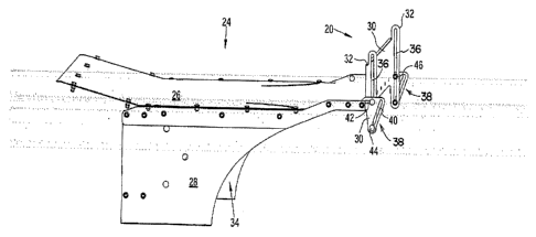
F1G. 1 shows a mower and crop processing implement 10 with a frame 12, a
running gear 14, a towbar 16, a mower and processing arrangement 18, and a
deflector 20.
The mower and processing implement 10 is shown as a towed implement, but
may equally welt be mounted on a towing vehicle or may be part of a self-
propelled
vehicle. The task of the mower and processing implement 10 is to mow crop
standing on the ground, to process it, and to deposit it to the rear in a
swath on the
ground.
The frame 12 is configured in a conventional manner as an inverted "U'", is
supported by the running gear 14, carries the mower and processing arrangement
18, and is connected by the towbar 16 to a towing vehicle, not shown.
In its simplest configuration, the running gear 14 consists of a wheel, not
described in any greater detail, on each side that is suspended from the frame
12 by
pivotable wheel support arms and servo motors (not shown).
The towbar 1C is used to connect the frame 12 to the towing vehicle and
extends
far ahead of the mower and processing arrangement 18.
The mower and processing arrangement 18 contains in a way not shown, but
known adequately, a mower head and a processing arrangement that follows it
downstream that is in the form of a rotor rotating about a horizontal axis,
that is
enclosed in a housing 22, which is followed by an outlet guide element 24. The
rotor
conveys, as an overshot conveyor, the crop that has been mowed and processed
to
the rear, that is, to the right in FIG. 1, where it is conducted along the
inner surface of
the outlet guide element 24 up to the deflector 20.
The deflector 20 is provided in the outlet region of the outlet guide element
24
and contains a planar element 30 and a slot carrier 32 on each side. The
deflector
20 is used to control the position of the crop in one swath on the ground, or
the
direction of its ejection. In that way, for example, a wide swath can be
produced in
that the planar element 30 deflects the flow of the crop in a region in which
the side
walls 28 maintain a large distance to each other. On the other hand, a narrow
swath
4
CA 02411982 2003-02-05
is produced when the planar element 30 does not impede the flow of the crop
and
lets it slide slang the side walls 28 converging towards each other. If the
mower and
processing arrangement is followed by a swath depositing arrangement, for
example, with a belt conveying in the sideways direction, that extends at an
angle to
the direction of operation of the mower and processing arrangement, a
corresponding orientation of the deflector 20 can also produce the result that
the
crop is deflected, on the one hand earlier and on the other hand later, so
that it can
be thrown on the entire length of the belt in its central region.
The planar element 30 is configured as a sheet metal component, but could also
consist of plastic or rubber or the like. ~n one of the edges extending
transverse to
the flow of the crop, a flanged edge at 90° is provided that assures
adequate
stiffness in bending. The planar element 30 extends over the entire width at
the end
of a tapered outlet channel 33 formed between the side walls 28. The planar
element 30 can be provided with creases, ribs or the like that increase its
stiffness
further. In addition, further guide elements could be provided on its guide
side.
The slot carriers 32 are configured as flat ribs that extend at an angle of
approximately 90° to the planar element 30 and are fastened to it. The
slot carriers
32 extend on both sides beyond the planar element 30, in particular on one
side
more than on the other side. In each slot carrier 32, a straight first slot 36
is provided
that extends parallel to the surface of the planar element 30.
In this embodiment, the planar element 30 and the slot carriers 32 are
configured
as a single part that is formed by a sheet metal plate, stamped in a press,
and
flanged to correspond. Alternatively, these components could also be screwed
or
welded together. Broadly speaking, the deflector 20 takes the form of an "H",
where
the planar element 30 forms the crossbar.
The outlet guide element 24 is configured in the shape of a "U"- shaped sheet
metal channel that opens downward and contains a cover 26 and two side walls
28,
where in this special embodiment, the cover 26 extends beyond the side walls
28
towards the rear. The side walls 28 converge from the mower and processing
arrangement 18 to the outlet end. In the rear end region of the cover 26, a
further
slot carrier 38 is provided on each side.
CA 02411982 2003-02-05
The further slot carrier 38 takes the shape of a triangle that is stamped from
a
stable, yet flexible, sheet metal. The further slot carriers 38 are connected
with the
cover 26 and/or the particular side wall 28, and in each case extend
vertically; the
connection is made simply by a screw connection. in the slot carrier 38, a
second
and a third slot 40 and 42, are provided that also extend in a straight line.
In the
assembled condition of the slot carrier 38, the slot 40 extends nearly
vertically, but
slightly inclined, and is relatively long. The slot 42 extends horizontally
along the
upper edge of the slot carrier 38 and is relatively short. The slots 40 and 42
are
separate from each other. The two slot carriers 38 are arranged parallel to
each
other and enclose the deflector 20 between them.
Finally, fixed positioning elements 44 and 46 are provided that extend in one
case through the first and the second slots 36 and 40, and in another case,
extend
through the first and the third slots 36 and 42. The fixed positioning
elements 44 and
46 are defined by screws, nuts, and washers that are arranged to hold the slot
carriers 32 and 38 against each other so that they cannot be separated.
On the basis of the foregoing description, the result is the following
assembly and
the following operation.
The deflector 20 is positioned between the two vertical slot carriers 38 in
such a
way that the first slot 36 in the slot carrier 32 of the deflector 20
intersects the second
slot 40 as well as the third slot 42 of the slot carrier 38 on the outlet
guide element
24. As soon as this has taken place, the fixed positioning elements 44 and 46
are
inserted and tightened. FIGS. 2 through 7 show five differing positions of the
deflector 20 that are possible on the basis of the use of the several slots
36, 40, and
42.
In that way, FIG. 2 shows an orientation in which the planar element 30
extends
vertically above the cover 26 and does not touch the flow of the crop. In this
position, the upper positioning element 46 is located at the rear end of the
slot 42
and an intermediate location of the slot 36, while the lower positioning
element 44 is
located at the lower ends of the slots 42 and 40.
FIG. 3 shows a position in which the fixed position elements 44 and 46 are
respectively located at or near the rear and upper ends of the second and the
third
6
CA 02411982 2003-02-05
slots 40 and 42 while they are each positioned close to the center in the
first slot 36.
The planar element 30 now assumes a position inclined slightly downward in
which
the crop is deflected only to a small degree.
The position according to FIG. 4 corresponds in a certain respect to that of
FIG.
2, however, the deflector 20 is here shown located at the very bottom of its
range of
movement wherein it fully extends into the flow of the crop. In this case, the
positioning elements 46 are in contact with the upper end of the first slots
36. The
position of the positioning elements 44 and 46 in the second and the third
slots 40
and 42 corresponds to that of FIG. 2.
FIGS. 5 and 6 demonstrate a position of the deflector 20, in which it and
particularly its planar element 30, is twisted, While the fixed positioning
elements 44
and 46 are arranged in the central region of the first slot 36, they occupy
differing
pasitions in the second and the third slots 40 and 42 that result in the
twisting.
Finally from FIG. 7, a position of the deflector 20 is revealed in which it is
oriented
at an angle, so that its left side is at a greater distance to the ground than
its right
side, resulting in a deflection of the flow of the crop towards one side. In
the
illustration that is somewhat exaggerated, the fixed positioning element 44 is
located,
on the one hand, at one end of the slot 36, and on the other hand, the fixed
positioning element 46 is located at the other end of the slot 36 on the
opposite side.
Such an orientation is possible, among other reasons, because the slot
carriers 32
and 38 can deflect.
Having described the preferred embodiment, it will become apparent that
various
modifications can be made without departing from the scope of the invention as
defined in the accompanying claims.
7