Note: Descriptions are shown in the official language in which they were submitted.
CA 02412007 2002-12-06
WO 01/98580 PCT/CA01/00911
NONWOVEN INTERLOCKING STRIPS AND NONWOVEN INDUSTRIAL FABRICS ASSEMBLED
THEREFROM
FIEL~l7 OF THE INVENTION
This invention relates to nonwoven industrial fabrics
which are assembled from a plurality of nonwoven segments, each
of which is a plastics extrusion.
BACKGROUND OF THE INVENTION
Nonwoven industrial fabrics include any sheet product that
is manufactured for technical performance and functional
properties. Industrial fabrics were generally constructed
either by weaving, or by weft insertion warp knitting. An
increasing number of these fabrics are now manufactured by
other methods, such as:
(1) dry laying of fiber webs by carding or from air streams,
followed by bonding into a coherent fabric;
(2) wet laying of fibers by methods akin to paper making;
(3) spun laying or melt blowing by direct extrusion of a
molten polymer into a sheet of filaments followed by bonding;
and
(4) casting or extrusion of films which are subsequently
expanded, slit or perforated, or which are reinforced with
yarns.
These nonwoven industrial fabrics are generally suitable for
use in applications requiring either a low. textile weight(in
gm/m2) or a fine pore structure. These fabrics often lack a
tensile strength and other compensating mechanical properties,
but offer other compensating advantages. They also generally
lack significant internal void volume, stiffness, and an
ability to resist compaction under compressive loading.
It has been proposed by Baker et al . in EP 802, 280 to
manufacture nonwoven, high strength, industrial fabrics from
one or more segments which include integral jointing structures
1
CA 02412007 2002-12-06
WO 01/98580 PCT/CA01/00911
that engage and interlock with each other to join the segments
together. Although these fabrics are adequate for use in many
applications, they lack resilience and stiffness, and thus
cannot adequately accommodate externally imposed stresses, such
as compression, out of plane loading, and shear between the
layers. Resiliency and stiffness are important properties of
an industrial fabric intended for use in applications where
fluid is removed by mechanical means, such as by pressing, from
a material that is carried upon the fabric. A need therefore
exists for a nonwoven industrial fabric having greater
resilience, and resistance to compressive loading. Desirably,
such a fabric should also be capable of maintaining a void
volume between its surface layers while under compression.
The present invention seeks to provide an industrial
fabric in which cooperating linear interlocking,structures are
used to provide a joint between two contiguous faces of at
least two adjacent layers, in which each structure is produced
as a plastics extrusion. By careful choice of the cooperating
linear interlocking structures, it is possible to control the
mechanical properties of the fabric in ways that are not
possible in known industrial fabrics. Further, the cooperating
interlocking structures provide a means whereby opposed edges
of the assembled fabric may be joined without necessitating an
additionah seaming mechanisz~ or manufacturing step, for example
by joining opposed longitudinal edges. By means of the present
invention, it is now possible to construct an industrial fabric
which includes at least two layers wherein the cooperating
linear interlocking structures serve to interconnect the
layers, to join opposed fabric edges, and, to accommodate
externally imposed stresses, such as compressive loading, out-
of-plane bending, and shear between the layers of the fabric.
2
CA 02412007 2003-02-20
Hy careful choice c~f both the shape and relative
separation of each of the cooperating interlocking :atruetures.
which can be the same shape or da.fferent shapes, thi:~ inventiaz~.
makes it possible to construct a fabric that is capable of
resisting compressive loading of the fabric sQ that Iraid spaces
. . between the layers are iaaix~tained, because cv3lapse and
expansion of the fabric under cyclic Compressive loadi.ug occurs
in a more or less predictable manger. rt is also possible to
control various other fai~ric properties, such as the loCaticn
of the bending neutral plane within the fabric structure.
The fabrics of this inventiau therefore find utility 3n
a variety of specialized app7.iCations, such as for Exampl e, in
the press or dryer section. of a papermaking machine.
sur o~ Tx~ r~rrT~ar~
~n a fizst broad embodiment, the present invention seeks
to prozride a nanwoven industrial fabric, including at Zeast a
first layer ce.rrying at 3east one first linear in.terlocJcin.g
structure engaged with at least one second linear interlocking
structure carried by a second layer, wherein:
~ a ) the first and the s econd li~xear interlo ckir~.g
structures are each located an continuous continuous
faces of the first axed the second 3.ayer~
t; fbl the first acrd the second engaged linear 3nterlacking
structures provide a void volume .between the two
contiguous. faces of the two layers;
(c) each layer includes at least one segment carrying the
Z.inear interlocking structure, and
(dl the interlocking structures are constructei3 and
arranged to resist compressive ~Ioad~.ng after engage~a~ent_
in a second broad embodiment this invention also seeks to
provide a segment for use in the assembly of an i.r~.dustrial.
3
'l AMENDED SHEET w06-05-2002
CA 02412007 2003-02-20
fabric, the segment hav~.ra.g a predetermined length, width and
thickness wherein: .
(i) at least a first generally psar~.ar face of the segntezit
includes at least one linear irsterlocking 5tructctre
iii) the segme~.t i.s a plastics extrusions anal
(iii)'the at least one interlocking structure is r,.c~nstructad
and arranged to resist compxessive loading after engagemer~t.
Preferably, within each 3ayer the or each segment includes
a plurality of substantially garallei linear interlocking
structures.
Preferably, within each layer the segment or segments are
_.- chosen fram the group consisting of a strip and a panel.
Preferably, ~ within each layer. the segments are 1_ocated ixa.
an abutting relat.zonsh3p to the adjacent segment or segments.
Prefera7~ly, tire interlocking structures are Located in a
predetermined regular pattern cn each of the t~c~ntiguous
continuous faces.
Preferably, the first and the secand in,terlockira,g
structures are the same. Alternatively, the first axed the
second interlocking structures are either z~.ot the same, or the
i
second a.nterlockirig structure is a mirror ime.ge of the. first
irlterl.ockin.g structure.
Preferably, engagement of the cooperating interlocking
structures is irreversible, and the structures cannot be
disengaged after assembly, without the risk of significant
damage to the linear interlocking structures. .A~.ternati'vely,
engagement of the caogerating i.nteriocking structures i5
re~rersib,le, acrd the structures can be disengaged after
4
v2 AMENDED SHEET ~00-0~=2002
CA 02412007 2002-12-06
WO 01/98580 PCT/CA01/00911
assembly, without the risk of damage to the linear
interlocking structures.
Preferably, the segments are fabricated from a material
selected from the group consisting of: polyamides;
copolyamides; polyesters; copolyesters; polyolefins;
polyketones and polyarylene sulfides.
Preferably, a polyamide is chosen from the group
consisting of polyamide 6, 4/6, 6/6, 6/10 and 6/12.
Preferably a polyester is chosen from the group consisting
of polyethylene terephthalate (PET), polybutylene terephthalate
(PBT), polypropylene terephthalate (PPT), polytrimethylene
terephthalate (PTMT), polyethylene naphthalate (PEN), and
poly(cyclohexylene dimethylene terephthalate) (PCT).
Preferably the copolyester is poly(cyclohexylene
dimethylene terephthalate) acid modified (PCTA).
Preferably, the polyolefin is polypropylene.
Preferably, a polyketone is chosen from the group
consisting of polyetherketone (PEK) and polyetheretherketone
( PEEK ) .
Preferably, the polyarylene sulfide is polyphenylene
sulfide (PPS) .
The selection of an appropriate polymer for use in the
production of the segments will be indicated by the end use for
the industrial fabric, bearing in mind both the environment of
use and the mechanical loads to be placed upon the, fabric.
CA 02412007 2002-12-06
WO 01/98580 PCT/CA01/00911
Preferably, in each of the layers all of the segments are
fabricated from the same polymer. Alternatively, in each layer
the segments are fabricated from different polymers.
Preferably, where the segments in a layer are fabricated from
different polymers, each of the polymers is chosen to suit the
intended
use of the fabric, with particular attention to the
environmental conditions to which each layer will be exposed.
Preferably, the cooperating interlocking structures are
engaged by snap or .press fitting the cooperating linear
interlocking structures together. Alternately, the cooperating
interlocking structures are engaged by sliding the cooperating
interlocking structures together.
Conveniently, at least one of the layers may also include
non-cooperating interlocking structures, such as spike or hook
members, on a~third noncontiguous face that is adapted for the
attachment of another layer, such as a fibrous batt or other
nonwoven~assembly of fibers or foam. This concept is disclosed
by Baker in EP 802 280.
The dimensions of the segments from which the industrial
fabrics of this invention are assembled are selected in
accordance with the end use requirements of the fabric.
In a further embodiment of this invention, the segments
may be porous or nonporous. If the segments are required to
be nonporous, then no further processing should be required.
If the strips or panels are required to be porous it is
preferred that they be rendered porous prior to their assembly
into an assembled industrial fabric, for example by perforation
or other appropriate technique which causes minimum damage to
the interlocking structures. The fabrics of this invention may
6
CA 02412007 2002-12-06
WO 01/98580 PCT/CA01/00911
also be made porous after assembly of the segments by suitable
means such as laser or ultrasonic drilling. In using such
processes care must be taken to minimize if not completely
prevent damage to the interlocking structures.
Preferably, in a segment that has been rendered porous,
the porosity provides a total open area of from about 30o to
about 600 of the total surface area of the segment. More
preferably, the porosity is from about 35o to about 550. Most
preferably the porosity is from about 40o to about 50%. The
size, shape and location of the pores will be chosen to suit
the intended end use of the fabric.
The segments are assembled into a fabric with the jointing
structures in any suitable direction bearing in mind the
intended end use, and bearing in mind that these structures
impart a level of beam stiffness to the fabric along their
length direction. If the fabric is intended to be assembled
as a loop, at the joint the segment ends in each layer can be
offset, so that the segments in each layer overlap and the
jointing structures are used to close the loop, thus
eliminating the need for a separate seam structure. An offset
joint can thus be made with the linear jointing structures
oriented either parallel or perpendicular to the line of the
joint. The orientation will be chosen in light of the end use
for the fabric. An offset joint also facilitates installation
of the fabric for use, since the fabric can be manufactured to
the required length and closed to a loop when installed. The
amount of overlap is chosen to suit the conditions of use of
the fabric, particularly any imposed tensile stresses.
BRIEF DESCRIPTION OF THE DRAWINGS
The invention will now be described in further detail in
relation to attached Figures which illustrate cross sections
7
CA 02412007 2002-12-06
WO 01/98580 PCT/CA01/00911
of linear cooperating interlocking structures attached to
suitable segments.
Figures 1 - 10 and 19 show cooperating interlocking structures
which can be joined by sliding insertion of one structure
into the other and in which the interlocking structures
are substantially the same; and
Figures 11 - 18 show pairs of cooperating interlocking
structures which may be joined either by sliding
insertion or by snap fitting in which the interlocking
structures are significantly different.
In several of these Figures the interlocking structures
are shown both engaged and disengaged.
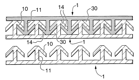
DETATLED DESCRIPTION OF THE DRAWINGS
In these Figures, a segment 1, which may be a strip or a
panel, carries a linear interlocking structure 10 on a
generally planar base layer 13. A segment 2, which also may
be a strip or a panel, carries either the same interlocking
structure 10, or a second different linear interlocking
structure 20. The segments 1 and 2 and the associated
interlocking structures are formed by extrusion of a suitable
thermoplastic material. The interlocking structure 10 includes
a support 11, and optionally a latching means 12, depending on
the shape of the interlocking structure 10 which may be
' desirable to engage securely two of the interlocking structures
together. Similarly, the interlocking structure 20 includes
a support 21 and. optionally a latching means 22. After
engagement of the interlocking structures a void volume 30 is
provided between two opposed segments.
Figures 1 - 10 and 19 illustrate cross sections of a first
group of linear interlocking structures. In each of these
Figures, the same interlocking structure is engageable with
8
CA 02412007 2002-12-06
WO 01/98580 PCT/CA01/00911
itself to provide the required joint. All of these structures
can be engaged by sliding insertion of one of a pair of
structures into the other; some of them can also be snap fitted
together.
Figure 1 is exemplary of this group; it cannot be snap
fitted together. Figure 1 shows segment 1 carrying a linear
interlocking structure 10, having a support 11 located on a
generally planar base layer 13. When assembled by rapier
insertion, a void volume 30 is formed between the segments, on
an axis substantially vertical to the plane of the Figure.
Each support 11 buttresses adjacent supports 11 so as~ to
maintain the void volume 30 under compressive loading of the
fabric by resisting collapse of the structures 10. In Figure
l it can also~be seen that the angled parts 14 of the structure
both aid in resisting compression, and also improve the beam
stiffness of the joint along a line in the plane of the Figure.
Figures 6, 9 and 19 show two further features of this
invention. In Figure 6, two arrangements are shown. In each
of them the segment 1, or both segments 1 and 2, carry the same
interlocking structure 10 on a support 11. Segment 2 can then
be either the same as segment 1, to provide the jointed
structure 40, or segment 2 can be a mirror image of segment 1,
to provide the jointed structure 50. Figure 9 takes this
concept a step further. The jointed structure 41 uses two
segments which are the same as segment 1. However it i.s
possible to alter the angle of the support 22 to the location
shown in the jointed structure 50. As the interlocking
structures 10 are asymmetrical, the segments 1 and 2 in the
structure 50 are not mirror images of each other. In Figure
19 the same approach is used, again by altering the angle of
the support 1l.,to the base layer 13. By altering the angle of
the support 11 in Figures 9 and l9 the manner in which the
9
CA 02412007 2002-12-06
WO 01/98580 PCT/CA01/00911
fabric resists compressive loading is changed. In one case,
the engaged linear jointing structures from essentially a
Warren truss structure which will resist compression so as to
maintain the void volume 30 between the two segments. In the
other case, the structures 10 will all collapse in the same
direction, and retention of the void volume 30 will depend on
the direction of the compressive load on the fabric. Thus
although the two arrangements 60 and 70 in Figure 19 look
similar, the interlocking structure 20 together with its
support 21 is not a mirror image of the interlocking structure
and its support 11, and the manner in which the fabric will
collapse is not the same. This is also the case for the
structure shown n Figure 9.
Figure 10 shows a further feature of this invention. The
segment 1 carries a jointing structure 10 carried by a support
11 on a generally planar base 13. The two interlocking
structures can be engaged together either by sliding or by a
snap fit. In this structure, the support 11 includes
cooperating latching members 12 which engage with each other
as the joint is closed to improve its integrity.
Inspection of Figures 1 and 3 shows that disengagement of
the two segments can only be done without the risk of
significant damage to the interlocking structures by sliding
them apart. A similar risk will exist for latched structures,
such as that shown in Figure 10. In contrast, inspection of
Figures 2 and 5 shows that disengagement of the two segments
does not imply significant damage to the jointing structures.
It will be apparent from these and the remaining Figures
that the linear interlocking structures create the void volume
30 between the segments used in the fabric. The manner in
which the engaged interlocking structures resist compressive
CA 02412007 2002-12-06
WO 01/98580 PCT/CA01/00911
loading will be determined by the cross sectional shape of the
engaged joint, and the size and location of the internal spaces
making up the void volume. These are chosen to provide a
fabric with the desired properties. The engaged linear
jointing structures also impart stiffness to the assembled
fabric, similar to that obtained from an "I" beam or truss
arrangement. The fabric flexibility along the linear joint can
thus be quite different to the fabric flexibility in a
direction perpendicular to the linear joint. Because the
cooperating interlocking structures. are not adhesively bonded
into place, the two jointed segments are capable of sliding
somewhat relative to each other, which improves the ability of
the fabric to resist imposed stresses. Thus, when the strips
or panels are oriented in the longitudinal direction (that is
towards the length of the assembled fabric), each may shift to
a small degree relative to the other. Such relative movement
will be useful in continuous process applications requiring the
fabric to bend about drive or turning rolls.
Within this group of Figures, the, structures shown in
Figures 2, 3, 10, and 11 can also be engaged by snap or press
fitting. The latching means 12 shown in Figure 11 can be
dimensioned and structured such that snap or press fit
engagement is possible.
Figure 2 is exemplary. In Figure 2 the segment 1 carries
a linear interlocking structure 10 on a support attached to a
generally planar base layer 13. The clearances of the arrow
head shape for the structure 10 permit the two segments to be
pressed into engagement. This Figure also shows a further
feature of this invention. The clearances around the arrow
head shapes will allow some level of movement of the engaged
segments relative to each other, including the ability to
11
CA 02412007 2002-12-06
WO 01/98580 PCT/CA01/00911
separate as far as the engaged structures 10 will allow, thus
altering the void volume to some extent.
Alternatively, the complementary interlocking structures
may be engaged together by bending the segment over a radius
perpendicular to the direction of the linear interlocking
structures so as to increase the size of the opening between
each of the structures 10, thereby allowing a second set of
structures to be pushed into engagement. This may be done in
a relatively simple manner by bending either one or both
segments over a curved"shoe".
Figures 10 - 18 illustrate cross sections of a second
group of linear interlocking structures. In each of these
Figures, two different interlocking structures are engaged to
provide the required joint, several of which include latching
structures. These are all engaged either by sliding insertion
or by snap fitting the two structures together as appropriate.
These Figures show a further feature of this invention.
Comparison of, for example Figures 14, 15 and 16 shows that the
cross sections of two structures making up the engaged joint
are very dissimilar. Since the location of the neutral bending
plane of the engaged joint depends bn the nature of the linear
jointing structures, the interlocking structure shapes in
combination in addition to being chosen to resist compressive
load, can also be chosen to locate the neutral plane nearer to
one surface of the fabric. The ability to achieve this is
important in some applications; for example when the fabric is
used to carry a paper web: location of the neutral plane near
to the paper web reduces stresses imposed on the paper web as
the paper web and fabric are wrapped'about carrying rollers.
22
CA 02412007 2002-12-06
WO 01/98580 PCT/CA01/00911
A further feature of this invention can also be seen from
a comparison of the two engaged structures 40 and.50 in Figure
6. In the engaged structure 40 all of the supports l1 are
essentially parallel, and hence under compressive load the
engaged linear jointing structures will collapse more easily
in the direction of the arrow X than in the direction of the
arrow Y. Tn contrast, in the engaged structure 50, the
supports are not parallel, and form a truss-like arrangement,
so that the engaged structure will resist compressive loads
more or less the same in the directions of both arrows X and
Y.
13