Note: Descriptions are shown in the official language in which they were submitted.
CA 02412063 2002-11-18
BIOMECHANICAL HEART VALVE PROSTHESIS AND
METHOD FOR MAKING SAME
Technical Field
The present invention relates to an implantable prosthetic device and,
more particularly, to biomechanical heart valve prosthesis and to a method for
making a biomechanical heart valve prosthesis.
Background
It is well known to utilize mechanical heart valves and natural tissue
cardiac valves to replace defective aortic and mitral valves in human
patients.
The decision to utilize a mechanical heart valve versus a natural tissue
product often is made at the discretion of the surgeon based on personal
preferences.
Common types of mechanical heart valves include ball check valves
and valves having one or more moveable lens-shaped discs. The discs may
be supported in cages for axial or pivotal movement within a frame structure.
The mechanical valves usually are formed of titanium and/or pyrolytic carbon
materials. A fabric sewing ring, such as formed of polymer or textile
material,
surrounds the annular frame to facilitate its implantation.
One type of natural tissue heart valve typically employs a porcine
valve for implantation in a human, as they are very similar to human valves of
appropriate size and generally are easy to procure. Prior art teaches the
concept of removing an aortic heart valve from a pig, treating it with an
appropriate fixation solution, which may include a glutaraldehyde solution,
and mounting the valve into a stent.
A stent typically is formed of a resilient material, such as a plastic
(e.g., DELRIN). Examples of various stent structures are disclosed in U.S.
Patent No. 3,983,581, U.S. Patent No. 4,035,849. The stent usually is
covered with a fabric material, such as DACRON, PTFE, or other suitable
textile material. The fabric material provides structure for securing the
valve
relative to the stent. The stented heart valve prosthesis may be implanted
into a patient for a heart valve replacement.
CA 02412063 2005-09-08
-2-
Summary
The following presents a simplified summary of the invention in order to
provide a basic understanding of some aspects of the invention. This
summary is not an extensive overview of the invention. It is intended to
neither identify key or critical elements of the invention nor delineate the
scope of the invention. Its sole purpose is to present some concepts of the
invention in a simplified form as a prelude to the more detailed description
that
is presented later.
The present invention relates to a system and method for providing a
biomechanical heart valve prosthesis, which includes biological tissue, such
as pericardium or collagen, associated with a mechanical heart valve.
According to one aspect of the present invention the heart valve prosthesis
includes a mechanical heart valve having a generally annular support and a
valve member that permits substantially unidirectional flow of blood through
the heart valve. For example, the mechanical valve could be a ball check
valve or other valve configuration, such as having one or more moveable
discs. One or more sheets of a biocompatible biological tissue material are
disposed around the annular support to define at least part of a sewing ring.
In accordance with a particular aspect, the mechanical heart valve may
include a fabric sewing ring. The biological tissue material thus may be
applied to cover the exposed fabric material.
Another aspect of the present invention provides a method of making a
heart valve prosthesis. The method includes providing a mechanical heart
valve that is operative to permit substantially unidirectional flow of blood
through the mechanical valve. One or more sheets of a biocompatible
biological tissue material are applied around an exterior portion of the
mechanical heart valve to provide a sewing ring that includes the biological
tissue material. If the mechanical heart valve includes a fabric sewing ring,
the biological tissue material is applied so as to cover the exposed fabric.
Accordingly, in one aspect of the present invention there is provided a
heart valve prosthesis, comprising:
CA 02412063 2005-09-08
-2a-
a mechanical heart valve having a generally annular support, the
mechanical heart valve being operative to permit substantially unidirectional
flow of blood through the mechanical heart valve; and
biocompatible biological tissue material disposed around the annular
support to define at least part of a sewing ring.
According to another aspect of the present invention there is provided
a heart valve prosthesis, comprising:
a mechanical heart valve having an annulus and a moveable part
supported within the annulus to permit generally unidirectional flow of blood
through the mechanical heart valve;
at least one sheet of a treated biological tissue material circumscribing
at least part of an exterior portion of the mechanical heart valve;
at least one retaining element operative to attach a radially inner
portion of the at least one sheet about the exterior portion of the mechanical
heart valve.
According to yet another aspect of the present invention there is
provided a heart valve prosthesis, comprising:
a mechanical heart valve having an annular support and a valve
member supported within the annular support to permit generally
unidirectional flow of blood through the mechanical heart valve;
a sewing ring of a fabric material disposed around the annular support
to form a fabric sewing ring; and
at least one sheet of a biocompatible biological tissue material covering
externally exposed portions of the fabric material.
According to still yet another aspect of the present invention there is
provided a heart valve prosthesis, comprising:
mechanical valve means for permitting substantially unidirectional flow
of blood through an annulus thereof;
treated, biocompatible biological tissue means for covering around the
annulus of the valve means and for providing a sewing ring to facilitate
implantation of the prosthesis; and
means for retaining the tissue means around the valve means.
CA 02412063 2005-09-08
-2b-
According to still yet another aspect of the present invention there is
provided a method of making a biomechanical heart valve prosthesis,
comprising:
providing a mechanical heart valve operative to permit substantially
unidirectional flow of blood through the mechanical heart valve; and
applying at least one sheet of a biocompatible biological tissue material
around an exterior portion of the mechanical heart valve to provide a sewing
ring that includes the biological tissue material.
According to still yet another aspect of the present invention there is
provided a heart valve prosthesis, comprising:
a generally cylindrical support;
a heart valve mounted within the support to permit substantially
unidirectional flow of blood through the heart valve; and
at least one sheet of biocompatible biological tissue material mounted
around and covering the support, one part of the at least one sheet defining a
sewing ring.
To the accomplishment of the foregoing and related ends, the
invention, then, comprises the features hereinafter fully described and
CA 02412063 2002-11-18
-3-
particularly pointed out in the claims. The following description and the
annexed drawings set forth in detail certain illustrative aspects of the
invention. These aspects are indicative, however, of but a few of the various
ways in which the principles of the invention may be employed. Other
objects, advantages and novel features of the invention will become apparent
from the following detailed description of the invention when considered in
conjunction with the drawings.
Brief Description of the Drawings
Fig. 1 is an isometric view of a heart valve mounted in a fabric-covered
stent;
Fig. 2 is an isometric view of a fabric-covered stent;
Fig. 3 is a plan view of sheets of biological material that may be
employed to form a heart valve prosthesis in accordance with the present
invention;
Fig. 4 is an exploded isometric view of a heart valve prosthesis in
accordance with the present invention;
Fig. 5 is an isometric view of an inflow side of heart valve prosthesis in
accordance with the present invention;
Fig. 6 is an isometric view of an outflow side of a heart valve prosthesis
in accordance with the present invention;
Fig. 7 is a partial side-sectional view of a stented heart valve taken
along line 7-7 of Fig. 4;
Fig. 8 is a partial side sectional view of a stented heart valve taken
along line 8-8 of Fig. 5;
Fig. 9 is an isometric view of fabric-covered stent that is covered with
biological tissue material in accordance with the present invention;
Fig. 10 is a partially exploded view of an example of a biomechanical
heart valve prosthesis in accordance with the present invention;
Fig. 11 is a view of a biomechanical heart valve prosthesis in
accordance with the present invention;
CA 02412063 2002-11-18
-4-
Fig. 12 is a cross-sectional view of the biomechanical heart valve
prosthesis taken along line 12-12 of Fig. 11;
Fig. 13 is an exploded view of a biomechanical heart valve prosthesis
in accordance with the present invention;
Fig. 14 is a cross-sectional view of a biomechanical heart valve
prosthesis, in accordance with the present invention, illustrating the
prosthesis
at an intermediate stage of manufacture;
Fig. 15 is a partial cross-sectional view of a biomechanical heart valve
prosthesis, in accordance with the present invention, illustrating the
prosthesis
at another stage of manufacture;
Fig. 16 is a cross-sectional view of a biomechanical heart valve
prosthesis in accordance with the present invention; and
Fig. 17 is an example of another biomechanical heart valve prosthesis,
in accordance with the present invention, illustrating an additional ring to
facilitate rotation of part of a mechanical heart valve.
Description of the Invention
Various aspects of the present invention will now be described with
reference to the drawings, wherein like reference numerals are used to refer
to like elements throughout related views.
Fig. 1 illustrates a stented heart valve 10, which may be employed to
form a biologically covered heart valve prosthesis in accordance with the
present invention. The stented heart valve 10 includes a heart valve 12
mounted or attached within in a conventional stent 14. The stented heart
valve 10, for example, is of the type disclosed in U.S. Patent No. 5,861,028
or
U.S. Patent No. 5,855,602, although other valve configurations (e.g., natural
tissue or mechanical valves) also may be utilized without departing from the
scope of the present invention.
By way of example, the valve 12 is a natural tissue heart valve, such as
a porcine heart valve, which has been trimmed and fixed in an appropriate
glutaraldehyde solution. An example of a suitable fixation environment is
disclosed in U.S. Patent No. 5,861,028. The valve 12 includes an inflow end
CA 02412063 2002-11-18
_5_
16, an outflow end 18 and a central axis, indicated at A, extending
longitudinally through the inflow and outflow ends of the valve. The valve 12
also includes a plurality of leaflets or cusps 20, 22 and 24 mounted within a
generally cylindrical sidewall portion 26 (see, e.g., cross sectional view of
Figs: 7 and 8), which may be a length of valve wall extending between the
inflow and outflow ends 16 and 18. The sidewall portion includes
circumferentially spaced apart commissures 28, 30, and 32, which form struts
at the outflow end 18 near the juncture of adjacent pair of leaflets. The
heart
valve 12 also has sinuses 34, 36, and 38 formed in the outflow end 18 of the
valve 10 between adjacent pairs of commissures 28 and 30, 30 and 32, 32
and 28, respectively.
Fig. 2 illustrates an example of the stent 14 illustrated in Fig. 1. The
stent 14 includes an annular base portion 40 and elongated stem posts (or
struts) 42, 44 and 46 extending from the annular base portion that correspond
generally to the anatomical configuration of the heart valve 12. The stem
posts 42, 44 and 46 are circumferentially spaced apart along an outflow end
50 of the base portion 40 to generally correspond to the radial positioning of
the individual leaflets of the heart valve 12 (Fig. 1 ). The stent 14 also
includes
an inflow end 48 spaced axially from the outflow end 50.
The stent 14, for example, may be manufactured in various sizes and
shapes by a conventional injection molding process. The stent 14 is typically
formed of a thermoplastic material, such as the material known commercially
as Delrin. The scent may be formed, however, of any other resilient, rigid, or
flexible material according to the desired level of stiffness.
At least an exterior portion, although typically the entire stent structure
14 is covered with a nonabsorbent fabric material 52. The fabric covering is
applied over and covers both the internal and external surfaces of the stem
14. By way of example, the fabric covering 52 may be an open mesh sheet of
flexible material, such as a Dacron polymer cloth, a textile, or substantially
equivalent material. It is to be appreciated that other fabric materials, such
as
plastics, synthetic materials, and the like also may be used. The fabric
CA 02412063 2002-11-18
covering provides structure to which the valve 12 (Fig. 1 ) may be secured
relative to the stent 14.
A generally annular implantation flange (or sewing ring) 54 may
circumscribe the stent base 40 intermediate the inflow end 48 and the outflow
end 50 of the stent 14. The flange 54, for example, is formed of the same
material as the fabric covering 52. The flange 54 may be attached about the
exterior of stem 14, such as by sewing the flange to the fabric covering 52
that
surrounds the stent 14. Alternatively, the flange 54 may be formed from part
of the fabric covering 52 that covers the stent 14 when the fabric covering is
applied. The flange also may be ironed to form a substantially flat ring-like
structure circumscribing the stent base 40. The particular positioning of the
implantation flange 54 may depend upon whether the prosthesis 10.is to be
implanted as a mural valve or an aortic valve (See, e.g., U.S. Patent No.
5,861,028). Examples of other types of stent structures that may be utilized
include those disclosed in U.S. Patent No. 3,983,581, U.S. Patent No.
4,035,849, as well as any other stent structure known in the art.
Fig. 3 illustrates a plurality of sheets 70, 72, 74, 76, and 78 of biological
tissue that may be utilized, in accordance with an aspect of the present
invention, to cover all fabric 52 that is exposed on a stented heart valve 12
(Fig. 1 ). The biological tissue, for example, is smooth animal pericardium
(e.g., equine, bovine, porcine, etc.) that has been tanned or fixed in a
suitable
tanning environment. The tanned tissue also may be treated with heparin to
improve its biocompatibility and mitigate thrombus formation.
Sheets 70 and 72 are in the form of generally annular rings, each
having a respective inner diameter 80, 82 and outer diameter 84, 86. In
particular, the ring 72 is dimensioned and configured for attachment to an
inflow end of a stented valve 10 (Fig. 1 ) and, thus, has an inner diameter 82
that approximates the dimensions and configuration of the valve at the
juncture between the valve and the fabric covering 52 located at the inflow
end of the stented valve. The other ring 70 is dimensioned and configured to
be attached to the outflow side of the implantation flange 54 (Figs. 1 and 2).
Each of the rings 70, 72 has a respective inner periphery 88, 90.
CA 02412063 2002-11-18
-7-
The remaining sheets 74-78 are in the form of patches that are
dimensioned and configured to cover the remaining exposed fabric of the
stented valve 10 (Fig. 1 ), namely, along the exterior of the stent posts 42-
46
(Figs. 1 and 2). While the patches are generally trapezoidal, it is to be
understood and appreciated that other shapes may be used. For example,
the shape of the patch may be selected according to the configuration of the
stented valve and the contour of the exposed fabric material covering along
the stent post andlor heart valve.
Fig. 4 is an exploded view of a heart valve prosthesis 100, in
accordance with an aspect of the present invention, in which identical
reference numbers are used to refer to parts previously identified with
respect
to Figs. 1-3. The sheets of biological (e.g., pericardial) tissue 70-78 are
aligned for attachment onto the stented valve 10, such that their visceral, or
smooth, side is exposed. In particular, the ring 70 is oriented coaxially with
axis A for attachment onto the inflow side of the implantation flange 54. As
mentioned above, the inner diameter 80 of the ring 70 approximates
(preferably slightly larger than) the outer diameter of the stented valve 10.
As
the ring 70 is mounted over the stent posts, the inner periphery 88 engages
and circumscribes the stented valve 10 and is positioned at the juncture of
the
flange 54 and the stent base portion 40.
Similarly, the other ring 72 is aligned coaxially with axis A for
attachment at the inflow end 16 of the scented valve 10. The inner diameter
82 is less than the outer diameter of the stented valve 10 at the inflow side
juncture of the implantation flange 54 and the stent. As mentioned above, the
inner diameter 82 of the ring 72 approximates the configuration of the inflow
annulus of the valve 12 at the juncture of the valve and the fabric covering
the
stent 14. As a result, the ring 72 is able to completely cover all exposed
fabric
52 at the inflow side, including the inflow side of the implantation flange
54.
The patches 74, 76, and 78 are aligned for attachment to cover
exposed fabric 52 associated with each of the stent posts 42, 44, and 46,
respectively. Once all the sheets are attached to the stented valve 10, no
fabric material 52 is exposed. As a result, when the prosthesis 100 is
CA 02412063 2002-11-18
_g_
implanted, there is no contact between blood and the fabric covering 52. This
mitigates clot formation and infection which otherwise might occur in response
to contact between blood and the fabric covering.
Figs. 5 and 6 illustrate the completed heart valve prosthesis 100 in
which all exposed fabric material has been covered with biological tissue in
accordance with an aspect of the present invention. In particular, Fig. 5
illustrates the prosthesis 100 as viewed from its outflow end. Each of the
patches 74, 76, 78 (only patch 74 is shown) is sewn to the fabric material
covering a radially outer portion of each respective stent post 42, 44, 46.
The
ring 70 engages and is connected to an outflow side of the implantation flange
and the ring 72 engages and is connected to an inflow side of the implantation
flange. The rings 70 and 72 are sewn together at an outer periphery thereof,
thereby "sandwiching" the flange located between the rings. In addition or
alternatively, the rings may be sewn to a perimeter to a portion of the
implantation flange 54.
The inner periphery 88 of the ring 70 also is sewn to an adjacent part of
the patches covering the radially outer portions the stent posts. Additional
sutures (not shown) also may be employed to connect the inner periphery 88
to an outer portion of stent 14 between stent posts.
Fig. 6 illustrates the inflow end of the prosthesis 100 in which the ring
72 completely covers the fabric at the inflow end 16 of the prosthesis. The
ring 72 is sewn at an inflow annulus 104 of the prosthesis 100 at the juncture
of the valve 12 and the fabric-covered stent. Advantageously, the ring 72 of
biological tissue conforms to the contour of at the inflow end, although
additional sutures may be employed to ensure substantially tight engagement
between the ring 72 and the stented heart valve 10.
Figs. 7 and 8 are cross-sectional views of part of valve structures
shown and described herein. It is to be appreciated that the dimensions and
relative position of corresponding parts has been exaggerated for purposes of
clarity of illustration.
Referring to Fig. 7, a cross-sectional view of part of the stented heart
valve of Fig. 4, taken along line 7-7, is illustrated. This further
illustrates the
CA 02412063 2002-11-18
-g-
fabric covering 52 that surrounds the stent 14. In addition, the implantation
flange 54 is illustrated as being spaced from the inflow end 16 of the valve
10.
A suture 108 may be employed to maintain the flange in a desire substantially
flat configuration. As mentioned above, the relative axial placement of the
implantation flange 54 on the stent 14 may vary according to whether the
prosthesis is to be used for mitral or atrioventricular valve replacement, and
all
such positions are within the scope of the present invention. Moreover, the
system and method, in accordance with an aspect of the present invention,
also may be employed with a stent or stented valve having no implantation
flange.
Fig. 8 is another cross-sectional view of part of the heart valve
prosthesis 100 of Fig. 5, taken along line 8-8, in accordance with an aspect
of
the present invention. The rings 70 and 72 sandwich the implantation flange
54 and are connected together along the periphery of the rings and flange by
appropriate sutures 106. As mentioned above, the sutures 106 alternatively
may connect the rings 70 and 72 to the flange 54. The inner periphery 88, 90
of each ring 70, 72 also is sewn to a corresponding portion of the stented
valve 10. In particular, the inner periphery 88 of the ring 70 is sewn to the
patches (e.g., 74) and also may be connected to the underlying fabric
covering 52 circumscribing the stented valve 10. The inner periphery of the
ring 72 is sewn to the inflow annulus 104 of the prosthesis 100 so as to cover
all fabric covering at the inflow portion of the stented valve. The biological
tissue patch 74 also is sewn to cover the exposed portion of the fabric
material associated with the stent post 42 (see, e.g., Fig. 5).
Fig. 9 is an example of a stent 200 that has been covered vi~ith
biological tissue in accordance with an aspect of the present invention. The
stent 200 includes a stent member 202 that has been covered with a fabric
material 204, such as shown and described with respect to Fig. 2. The stent
200 also includes stent posts 206, 208, and 210 extending substantially
coaxially from a stent base portion 212 in a circumferentially spaced apart
relationship.
CA 02412063 2002-11-18
-10-
Biological material has been applied to a the fabric-covered stem
member 202 in accordance with an aspect of the present invention. In
particular, the stent 200 includes an implantation flange 214 formed of a two
layers 216 and 218 of biological tissue (e.g., animal pericardium). Each of
the
layers 216, 218, for example, is in the form of a ring-like sheet of animal
pericardium, such as sheets 70 and 72 shown and described hereinabove.
The outer periphery of each of the layer is sewn together via sutures 220.
The radially inner portion of each of the layers 216, 218 also is sewn the
fabric
covering 204.
A Bayer 222 of biological tissue also covers the fabric material 204
covering the radially outer extent of the stent 200. This layer 222 may be in
the form of a single sheet of animal pericardium that circumscribes the fabric
covered stent 200. As illustrated in the example of Fig. 9, the layer 222 may
be trimmed to conform to the contour of the stent posts 206-210 along a
outflow end of the stent. The layer also may cover the fabric material 204 at
an outflow margin 224 of the stent member 202 so as to mitigate abrasion that
may occur upon contact between leaflets and the outflow rails. Because the
layer 220 typically is formed of an elongated sheet of the biological tissue,
a
butt seam 226 is exposed. The butt seam 226 of the sheet 222 may be
positioned intermediate stent posts 206 and 208, with two ends of the layer
222 seamed together end-to-end with substantially no overlap to define the
seam.
It is to be appreciated that the layer 220 may be applied to the stem
200 before or after formation of the implantation flange 214. For example, if
the stent 200 does not include a fabric implantation flange (as shown in Fig.
2), then the layer 220 may cover the entire radially outer portion of the
stent
member 202. A double layer (layers 216 and 218) biological material may
then be configured to form the implantation flange 214, with the inner portion
of each layer 210, 212 being secured to the stent outer layer 222 and/or to
the
underlying fabric covering 204. In contrast, if the stent 200 includes a
fabric
implantation flange, then the layer 222 may circumscribe an outflow portion of
CA 02412063 2002-11-18
-11-
the stent 200, such as from the juncture of the flange to the outflow end of
the
stent 200.
While in the example of Fig. 9, the radially inner portion of the stent
exposes same fabric material 214 (other than at the outflow margin 224), it is
to be appreciated that the inner portion also may be covered with a biological
material, such as animal pericardium. However, a heart valve mounted within
the stent 200 usually will completely cover the interior exposed portions of
the
fabric material.
Figs. 10-12 illustrate an example of a biomechanical heart valve
prosthesis 300 in accordance with an aspect of the present invention. Fig. 10
depicts a partially exploded view of the prosthesis 300. The prosthesis 300
includes a mechanical heart valve 302 having an associated sewing ring 304,
which is mounted coaxially around the valve. The heart valve 302 also
includes a generally annular base portion or annulus 306, which is formed of a
generally rigid material, such as pyrolytic carbon, a biocompatible plastic or
metal material, and the like.
As best shown in Fig. 12, the annulus 306 includes a generally
cylindrical portion 308 that extends axially between spaced apart end portions
310 and 312. The end portions 310 and 312 of the annulus 306 define flange
portions that extend radially outwardly relative to the intermediate
cylindrical
portion 308. The flange portions at the ends 310 and 312 help retain the
fabric sewing ring 304 at a desired axial position between the ends when
positioned around the valve 302. The sewing ring 304 thus is mounted over
and circumscribes an exterior part of the cylindrical portion 308 of the
annulus
306. An interior portion of the fabric sewing ring could be provided with
additional fabric material, cloth or other material to increase stiffness
and/or
provide a desired shape and contour of the fabric sewing ring.
The mechanical heart valve 302 also includes a valve portion 314
operative to permit substantially unidirectional flow of blood through the
mechanical heart valve 302. By way of example, the valve portion 314 is
moveable between an open condition (illustrated in phantom at 314') and a
closed condition. The valve portion 314 is illustrated as a generally circular
CA 02412063 2002-11-18
-12-
disc supported relative to the annulus 306 by a curved arm 316, which
extends from the annulus through a central aperture of the valve portion. The
valve portion 314 is moveable relative to (e.g., along) the arm 316 and
annulus 306 between open and closed conditions. The exemplary
mechanical heart valve 302 further includes fingers 318 that extend radially
inwardly from the cylindrical portion 306. The fingers 318 cooperate with the
pivot arm 316 to limit movement of the valve portion 314 between its open
and closed conditions.
Those skilled in the art will understand and appreciate that other types
and configurations of mechanical heart valves (e.g., ball-check heart valves,
etc.) may be utilized in accordance with an aspect of the present invention.
Examples of mechanical heart valves that may be utilized in accordance with
an aspect of the present invention are commercially available from various
manufacturers and associated distributors, such as, including Medtronic, Inc.,
Omniscience, fnc., St. Jude Medical, and others.
In accordance with an aspect of the present invention, the
biomechanical heart valve prosthesis 300 includes one or more sheets 320
and 322 of a biocompatible, biological tissue material. In the example of Fig.
10, two annular flat sheets 320 and 322 of the tissue material are illustrated
in
an axially exploded position at opposite sides of the heart valve 302. Each of
the rings 320 and 322 includes an inner circular edge portion 324, 326 and an
outer edge portion 328 and 330 spaced radially from each respective inner
edges. The inner edges 324 and 326 are dimensioned and configured to
have a diameter that approximates an outer diameter of the cylindrical portion
308 of the annulus 306. The rings 320 and 322 are employed to cover at
least exposed fabric material of the mechanical heart valve.
By way of illustration, the rings 320 and 322 are formed from one or
more sheets of a natural tissue material, such as animal pericardium (e.g.,
bovine, equine, porcine, human, etc.). The natural tissue material may be
chemically treated in a suitable fixation solution, such as including
glutaraldehyde. By way of further illustration, the rings 320 and 322 may be
formed from a NO-REACT~ patch, which is commercially available from
CA 02412063 2002-11-18
-13-
Shelhigh, fnc., of Miilburn, New Jersey. The NO-REACT~ patch helps
improve the biocompatibility of the resulting prosthesis 300, as shown in
Figs.
11 and 12, thereby mitigating the likelihood of a patient rejecting an
implanted
prosthesis. The NO-REACTC~ pericardial patch also resists calcification.
It is to be understood and appreciated that other types of biocompatible
materials (e.g., any biological tissue, collagen; as well as other natural
tissue
or synthetic materials) also could be utilized to cover the exposed fabric
material and provide a biomechanical heart valve prosthesis 300 in
accordance with the present invention. Therefore, by combining the treated
natural tissue ring or rings 320, 322 with a mechanical heart valve 300, in
accordance with an aspect of the present invention, the likelihood of
infection
after implantation of the prosthesis may be mitigated.
As shown in Figs. 11 and 12, each of the rings 320, 322 is positioned
near a respective end portion 310, 312 of the mechanical heart valve 302,
such that its inner edge 324, 326 engages a juncture of the associated end
portion and the sewing ring 304. For example, sutures 334 secure the inner
edges 324 and 326 relative to an adjacent part of the sewing ring 304 near
the respective end portions 310, 312.
Intermediate portions of the rings 320 and 322 extend from the sutures
334 and, in turn, cover the fabric sewing ring 304. That is, the outer edge
portions 328 and 330 of the respective rings 320 and 322 extend radially
outwardly from the annulus 306 to a position beyond an outer extent of the
fabric sewing ring 304. The biocompatible rings 320 and 322 thus sandwich
the fabric sewing ring 304.
The outer edge portions 328 and 330 of the respective rings 320 and
322 are sewn together, such as by sutures 336; to define a radial outer extent
of the biologically covered sewing ring. The sutures 336 also may extend
through a radially outer portion of the fabric sewing ring 304, as shown in
Fig.
12, to help anchor the rings 320 and 322 to the heart valve 302. As a result,
the combination of the rings 320 and 322 and an exterior portion of the
annulus 306 completely enclose the fabric sewing ring 304, such that no
remaining fabric material is exposed.
CA 02412063 2002-11-18
-14-
Additional sutures andlor surgical adhesive materials (not shown) could
be employed to help the rings 320 and 322 conform to the contour of the
particular fabric sewing ring 304.
In certain circumstances, it may be desirable to omit a fabric material
sewing ring from a mechanical heart valve. Figs. 13-16 illustrate another
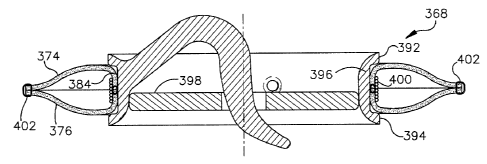
biomechanical heart valve prosthesis 368, in accordance with an aspect of the
present invention, having no fabric sewing ring.
Fig. 13 depicts an exploded view of the prosthesis 368, such as, for
example, at an early stage of manufacture. The prosthesis 368 includes a
sewing ring 370 of one or more sheets of a treated biocompatible biological
tissue material and a mechanical heart valve 372. The biological tissue
material may be substantially identical to that shown and described with
respect to Figs. 10-12.
In accordance with one aspect of the present invention, the sewing ring
370 is formed of a pair of annular rings 374 and 376. The rings 374 and 376
may be substantially identical in size and shape, although differently
configured rings also could be used in accordance with the present invention.
Each of the rings 374,376 includes a substantially circular inner edge 378,
380, which edges are sewn together by sutures 382 to define an inner portion
384 of the combined annular structure.
The rings 374 and 376 also include outer edges 386 and 388 spaced
radially outwardly from the inner edges 374 and 376, respectively. The outer
edges 386 and 388, for example, may be urged generally away from the inner
portion 384 of the rings 374 and 376 to provide a C-shaped cross-sectional
configuration, such as shown in Figs 13 and 14. The inner portion 384 of the
sewing ring 370, for example, has an inner diameter that generally
approximates or is slightly less than the outer diameter of the mechanical
heart valve 372, around which the ring is mounted, as shown in Fig. 14.
While Fig. 14 illustrates the biological sewing ring 370 positioned
around the heart valve 372 at an intermediate manufacturing stage, it is
appreciated that such configuration could be utilized to provide a pair of
CA 02412063 2002-11-18
-15-
sewing rings to implant a mechanical heart valve in accordance with the
present invention.
As another possible alternative, for example, the ring 370 could be
formed of a single sheet of an elongated biological tissue material, with ends
of the sheet being connected end to end to form a cylindrical ring. Such
alternative construction of the ring further includes side portions, which may
be urged radially outwardly away from the inner portion 384 to provide the C-
shaped cross-section, as shown in Fig. 14.
Referring back to Fig. 13, the heart valve 372 includes an annular
support 390 having ends 392 and 394 that are spaced apart from each other
by an intermediate, short cylindrical portion 396 of the support. A valve
portion 398 is mounted within the annulus of valve 372 to permit substantially
unidirectional flow of blood through the valve. For example, the valve portion
398 is moveable relative to the annular support 390 between an open
condition (illustrated in phantom at 398') and its closed condition.
Because the mechanical heart valve 372 in the example of Figs. 13-16
is substantially similar to the valve shown and described with respect to
Figs.
10-12, further description of the valve and its operation has been omitted for
sake of brevity. It is to be appreciated that other mechanical heart valve
configurations different from that shown herein could be utilized in
accordance
with an aspect of the present invention (e.g., ball check valves, valves with
multiple moving valve members, valve members fixed to pivot arms, etc.).
As mentioned above, Fig. 14 depicts the C-shaped ring 370 mounted
around the annular support 390 exterior of the heart valve 372 according to an
aspect of the present invention. The inner portion 384 of the ring 370, for
example, engages and circumscribes an external part of the cylindrical portion
396 of the valve 372. Accordingly, the flange portions at the ends 392 and
394 of the valve 372 help hold the biological sewing ring 370 between the
ends.
With reference to Fig. 15, to further inhibit movement of the ring 370
relative to the heart valve 372, one or more retaining features 400 may be
applied to the inner portion 384 of the ring 370 to hold the ring in
engagement
CA 02412063 2002-11-18
-16-
with the generally rigid cylindrical portion 396 of the valve 372. In
accordance
with a particular aspect of the present invention, the retaining feature 400
includes one or more sutures that extend circumferentially around the inner
portion 384 of the ring 370 and the cylindrical portion 378 of the heart valve
372, such as shown in Fig. 15.
By way of illustration, as shown in Fig. 15, the retaining feature 400
includes a plurality of windings of a relatively thick sterile suture material
applied around the ring 370 and the cylindrical portion 378. Such windings of
the retaining feature 400 may be overlapping or nan-overlapping between the
ends 376 and 378 of the valve 372. As a result of wrapping the sutures
around the biological ring 370 and mechanical heart valve 372 for several
turns, the attachment of the ring to the valve is improved.
Those skilled in the art will understand and appreciate various types of
retaining features 400 that could be utilized to hold the inner portion 384 of
the
ring 370 against the cylindrical portion 378 of the valve 372. By way of
example, instead of sutures, one or more rings of suitable biocompatible
material, such as biological tissue, fabric, synthetic materials, etc., may be
applied around the ring 370 and the annular support 390 of the valve 372. In
addition, valve 372 itself could be reconfigured to permit sutures or other
means to be applied through part of the valve to anchor the biological ring
370
relative to the valve.
Fig. 16 illustrates the heart valve prosthesis 368, which may be formed
from the structure shown in Fig. 15, in accordance with an aspect of the
present invention. The resulting prosthesis 368, for example, may be
produced from the structure illustrated in Fig. 15 by connecting the outer
edge
portions 386 and 388 to each other, such as by sutures 402. In particular, the
outer edges 386 and 388 of the annular rings 374 and 376 are sewn together,
such that the rings collectively form a generally tubular ring structure that
encloses the retaining sutures 400. in addition, the outer edges 386 and 388
of the rings 374 and 376 define a radially outer extent of the biomechanical
heart valve prosthesis 368.
CA 02412063 2002-11-18
-17-
Fig. 17 illustrates another example of a biomechanical heart valve
prosthesis 420 in accordance with an aspect of the present invention. The
prosthesis 420 includes a mechanical heart valve 422 and a ring 424 of a
biological tissue material that covers an exterior portion of the heart valve
in
accordance with an aspect of the present invention.
In this example, the mechanical heart valve 422 is substantially similar
to the examples of Figs. 10-16 and, thus, further description of the
mechanical
heart valve and its operation has been omitted for sake of brevity. Briefly
stated, the mechanical heart valve 422 includes an inner annular support 426
to which a valve portion (e.g., a disc) 428 is moveably mounted to permit
substantially unidirectional flow of blood through the valve. In addition, the
mechanical heart valve 422 includes an outer ring 430 mounted around the
annular support 426 to permit rotation of the annular support and associated
valve portion 428 relative to the outer ring. The outer ring 430 thus defines
an
outer annulus of the mechanical heart valve 422. By way of illustration, the
outer ring 430 is useful during implantation of the prosthesis 420 to rotate
the
support 426 and the valve portion 428 at a desired angular orientation
relative
to the heart.
The biological tissue ring 424 is positioned around the outer ring 430 to
define a biological tissue sewing ring to facilitate implantation of the
prosthesis
420. In accordance with one aspect, the biological ring 424 defines a tubular
ring having an interior in which a retaining feature 432 (e.g., one or more
sutures) holds the biological ring against an exterior surface of the outer
ring
430. Radialfy outer edges 434 and 436 of the sewing ring 424 are connected
together (e.g., by sutures 438) to provide a tubular ring configuration, as
shown in Fig. 17.
Alternatively, if the mechanical heart valve 422 includes a fabric sewing
ring, similar to the example of Figs. 10-12, the biological tissue material
may
be applied to cover the exposed fabric material of sewing ring. The sewing
ring, for example, would circumscribe the outer ring 430. As a result, during
implantation, the inner support ring 426 and associated valve 428 may be
rotated relative to the outer ring 430 and the biological sewing ring. Those
CA 02412063 2002-11-18
-18-
skilled in the art will understand and appreciate various other configurations
of
mechanical heart valves that may be implemented in accordance with an
aspect of the present invention.
In certain circumstances, it may be desirable to store in a dry condition
a biological tissue sewing ring andlor a mechanical heart valve prosthesis
having a sewing ring that includes biological tissue in accordance with an
aspect of the present invention. It further may be desirable to keep the
biological tissue material generally soft and pliable to facilitate its
implantation.
In order to provide a pliable biological ring, in accordance with an
aspect of the present invention, the biological tissue may be immersed in a
sterile solution of glycerin, such as after an appropriate fixation treatment
andlor detoxification. By way of further illustration, the biological tissue
material may be immersed in a solution having about 2% to about 25%
glycerin for a time period of about one to about five hours. After such
treatment, the biological tissue material of the biomechanical heart valve may
be removed from the solution and dried, such that its moisture is removed.
Advantageously, some of the glycerin penetrates the tissue and remains in
the tissue so as to maintain the tissue in a pliable condition, even after
being
dried.
It is to be appreciated that the immersion of the tissue in the glycerin
solution may occur. before attachment of the tissue to the mechanical heart
valve. In addition or alternatively, the immersion into the glycerin solution
may
be performed while the tissue is attached to the mechanical heart valve in
accordance with an aspect of the present invention. Those skilled in the art
will understand and appreciate other suitable solutions that may be utilized
to
help maintain the biological tissue material in a pliable condition even after
it
has been dried.
In view of the foregoing structures and methodology, it will be
appreciated by those skilled in the art that a system and method implemented
according to the present invention help reduce a possible source of infection
after the valve is implanted. fn particular, a prosthesis implemented in
accordance with the present invention, mitigates contact between fabric
CA 02412063 2002-11-18
-19-
material (e.g., polymer materials, such as PTFE, or textiles) and blood. Once
infection mounts in fabric material, it is practically impossible to
eradicate. As
a result, the patient may require re-operation, which exposes the patient to
additional risk that has a relatively high mortality rate. The fabric
material, if
left exposed to blood, also provides a site that is prone to clot formation,
which may result in other complications for the patient. As a result, the
present invention provides a heart valve prosthesis that mitigates clot
formation as well as helps reduce the incidence of infection. The biological
material covering also tends to improve the compatibility between the heart
valve prosthesis and the valve recipient.
What has been described above are examples of the present invention.
It is, of course, not possible to describe every conceivable combination of
components or methodologies for purposes of describing the present
invention, but one of ordinary skill in the art will recognize that many
further
combinations and permutations of the present invention are possible. For
example, various types of heart valves, which may be different from those
shown and described herein (e.g., ball check mechanical valves, etc.), can
benefit from applying biological tissue around such valves in accordance with
an aspect of the present invention. Accordingly, the present invention is
intended to embrace all such alterations, modifications and variations that
fall
within the spirit and scope of the appended claims.