Note: Descriptions are shown in the official language in which they were submitted.
CA 02412212 2002-11-19
Specification of the Patent of Invention for: "A SANITARY NAPKIN"
The present invention relates to a sanitary napkin for absorbing
bodily exudates, such as menstruation liquids and urine, enhancing the
wearer's comfort.
Background of the Invention
It is well-known that conventional sanitary napkins have a sub-
stantially planar elongate shape. Although many of the more ancient sanitary
napkins are substantially rectangular in shape, having straight side edges, a
number of more recent sanitary napkins have been molded so as to improve
the adjust of the contours of the body of a wearer, for instance in the form
of
an hourglass. These hourglass-shaped sanitary napkins have absorbent por-
tions, the maximum breadth of which is located in the end regions of the
product, that it to say, generally up to 1/6 of its length as measured inwards
from the distal end of the sanitary napkin. However, it has been found that
these sanitary napkins have a number of drawbacks, which are described
below.
In the first place, these sanitary napkins are inefficient, since they
have a larger amount of absorbent material in the end regions of the sanitary
napkin, which are regions in which leakage hardly occurs, and a smaller
amount of absorbent material in a central region, which is adapted to be lo-
cated between the wearer's thighs.
Secondly, the excess material in the end regions and the ab-
sence of material in the region between the thighs cause a deformation in the
sanitary napkin, due to this accumulation of material, which causes discom-
fort in use and may lead to leakage of the bodily exudate.
Summary of the Invention
An objective of the present invention is to provide a sanitary nap-
kin having an end portion that is substantially thin, provides an absorption
capacity comparable with that of conventionally molded sanitary napkins and
brings about excellent comfort in use.
The objectives of the present invention are achieved by means of
a sanitary napkin comprising an absorbent portion that has a first transverse
CA 02412212 2010-03-01
2
end and a second opposite transverse end, which define a length between
themselves, a first longitudinal side edge and a second opposite longitudinal
side
edge, which define a breadth between themselves, the breadth varying along the
length of the absorbent portion, wherein:
(i) a first breadth is located between 1/5 and less than 1/2 of the
length of the absorbent portion, measured from the first
transverse end, the first breadth being larger than any
breadth of the absorbent portion located between the first
transverse end and the first breadth;
(ii) a second breadth located substantially from 1/5 to less than
%2 of the length of the absorbent portion, as measured from
the second transverse end, the second breadth being
smaller then or equal to the first breadth;
(iii) a central region intermediate between the first breadth and
the second breadth, the central region having a maximum
breadth that is smaller then or equal to the first breadth;
wherein the absorbent portion has a plurality of elongate embossed channels.
Each channel being spaced apart from an adjacent channel and extending
obliquely with respect to a longitudinal axis from one side of the napkin to
an
opposite side of the napkin.
Brief Description of the Drawings
The present invention will now be described in greater details with
reference to an embodiment represented in the drawings. The figures show:
Figure 1 is a perspective view of a first embodiment of the
sanitary napkin of the present invention;
CA 02412212 2010-03-01
2a
Figure 2 is a top view of the sanitary napkin illustrated in
Figure 1;
- Figure 3 is a bottom view of the sanitary napkin illustrated in
figures 1 and 2;
- Figure 4 is a perspective view of a second embodiment of
the sanitary napkin of the present invention;
Figure 5 is a top view of the sanitary napkin illustrated in
figure 4;
- Figure 6 is a bottom view of the sanitary napkin illustrated in
figures 4 and 5;
CA 02412212 2002-11-19
3
- Figure 7 is a perspective view of a third embodiment of the
sanitary napkin of the present invention;
- Figure 8 is a top view of the sanitary napkin illustrated in figure
7; .
- Figure 9 is a bottom view of the sanitary napkin illustrated in
Figures 7 and 8;
- Figure 10 is a perspective view of a fourth embodiment of the
sanitary napkin of the present invention;
- Figure 11 is a top view of the sanitary napkin illustrated in Fig-
ure 10:
- Figure 12 is a bottom view of the sanitary napkin illustrated in
Figures 10 and 11;
- Figure 13 is a schematic cross-section view of a first version of
the first and second embodiments of the sanitary napkin of the present in-
vention;
- Figure 14 is a schematic cross-section view of a second version
of the first and third embodiments of the sanitary napkin of the present in-
vention;
- Figure 15 is a schematic cross-section view of a first version of
the second and fourth embodiments of the sanitary napkin of the present in-
vention;
- Figure 16 is a schematic cross-section view of a second version
of the second and fourth embodiments of the sanitary napkin of the present
invention.
Detailed Description of the Invention
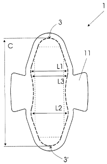
According to a first embodiment, as shown in Figure 1, the sani-
tary napkin 1 of the present invention comprises a substantially planar and
elongate absorbent portion 2, which forms a main body or chassis of the
sanitary napkin. The absorbent portion 2 comprises a layer of liquid-
permeable material, a layer of liquid-impermeable material and an absorbent
core between the liquid-permeable layer and the liquid-impermeable layer.
The absorbent portion 2 comprises a transverse main end 3, from which it
CA 02412212 2002-11-19
4
extends as far as a second transverse main end 3'. The absorbent portion 2
also has a first longitudinal side edge and a second opposite longitudinal
side edge.
The total length C of the absorbent portion 2 is the distance be-
tween the first main end 3 and the second main end 3'. The absorbent por-
tion 2 has a breadth that varies along its length. The breadth is measured as
being the distance between the first longitudinal side edge and the second
longitudinal side edge along a line that is perpendicular to an imaginary lon-
gitudinal central line, that is to say, it is substantially perpendicular to
the
length C of the absorbent portion 2. The length C has a value greater than
that of any breadth of the absorbent portion 2, which are described below.
The absorbent portion 2 has a maximum breadth L1 (hereinafter
indicated as a first breadth) located between 1/5 and '/2 of the value of the
length C of the absorbent portion 2 measured from the first main end 3, and
preferably this breadth L1 is located at about 1/3 of said value of the length
C. The value of L1 is greater than that of any breadth of the absorbent por-
tion 2 in the region between the first transverse end 3 and the first breadth
L1. The region between L1 and the first transverse end 3 is smaller than L1
and, preferably, tapers in a linear way from L1 to the first transverse end 3,
as shown in Figure 1.
Consequently, the breadth of the absorbent portion 2 increases
between the firs main end 3 (where this value is zero) and the distance be-
tween 1/5 and %2 of its longitudinal length, where the breadth is maximum.
Preferably, but not compulsorily, the breadth increases linearly with respect
to the increase of the distance between the first transverse end 3 and the
distance between 1/5 and '/2 of the longitudinal length C. The absorbent por-
tion 2 comprises a second breadth L2 located between 1 /5 - '/2 of the value
of the length C of the absorbent portion 2, measured from the second trans-
verse end 3. The value If L2 is smaller that or equal to the value of L1. The
value of L2 is greater than any breadth of the absorbent portion 2 between
the second transverse end 3 and the distance between 1/5 and 1/2 of its lon-
gitudinal length C. The absorbent portion 2 also has a central region inter-
CA 02412212 2002-11-19
mediate between the first breadth L1 and the second breadth L2, the central
region having a maximum breadth L3 that is smaller than or equal to the first
breadth L1. In a preferred embodiment, L1 and L2 are substantially equal,
L3 is smaller than L1 and L2, and the longitudinal side edges of the absorb-
5 ent portion 2 in the central region are arcuate, in a convex orientation in-
wards, to form an hourglass-shaped structure. This means that the end
edges of the absorbent portion 2 are substantially curve it its central
region,
the centers of the radii of curvature of the edges are located substantially
out
of the absorbent portion 2, in such a way that this central region is substan-
tially anatomic, bringing about an optimized fitting into the region between
the
thighs of the wearer with a smooth movement of her thighs, providing comfort
in use and the feeling of not being wearing the sanitary napkin.
This constructive arrangement characterizes a more anatomical
central region, and the narrower ends result in less deformation of the prod-
uct in use by virtue of the substantial reduction of material in these
regions,
which brings about the required protection with more comfort and discretion.
This characteristic may be present either at the two ends or at the first
trans-
verse end 3 of the sanitary napkin 1.
In the case of the two ends of the absorbent portion 2 with this
geometric construction, the first and the second main ends 3, 3' are
indistinct,
and the values of the length of the portion 2 may be taken from any one of
these ends 3, 3'.
A first version of the sanitary napkin 1 comprises a layer of liquid-
impermeable material 4, the inner surface of which is joined by the construc-
tion adhesive 5 to a first surface of a transfer layer 6, the second surface
of
which, in turn, is joined to one first surface of an absorbent core 7 (which
is
capable of absorbing liquid exudates), the second surface of which is joined
to a first surface, or to the inner surface, of a layer of liquid-impermeable
material as a liquid-impermeable plastic film 8, also by means of the con-
struction adhesive 5. Any conventional liquid-permeable materials, liquid-
impermeable materials, transfer layers and absorbent materials that are well
known from the prior art are suitable for use in the present invention.
CA 02412212 2002-11-19
6
The liquid-permeable layer 4 may be formed from any flexible
liquid-permeable material that does not cause irritation to an wearer. The
suitable liquid-permeable materials include but are not limited to woven fab-
rics, non-woven fabrics, plastic films with openings and the like. The liquid-
permeable layer 4 is preferably a high-transposition non-woven mesh mate-
rial, bulky and of relatively low density. The liquid-permeable layer may be
composed either by a single type of fiber such as polyester or polypropilene
or by 2-component or conjugated fibers, which have one component of low
melting point and one component of high melting point. These fibers may be
selected from a variety of natural or synthetic materials such as nylon, poly-
ester, rayon (in combination with other fibers), cotton, acrylic fiber or
others,
and combinations thereof.
The liquid-impermeable layer 4 preferably has a relatively high
degree of wettability, although the individual fibers used for forming this
layer
may not be particularly hydrophilic. The liquid-permeable material of the
layer
should also contain a great number of relatively large pores. This occurs be-
cause the liquid-permeable layer should absorb the bodily fluid rapidly and
carry it away from the body and from the deposition point. Advantageously,
the fibers that compose the liquid-impermeable layer should not lose their
physical properties when they are wetted. In other words, they should not
collapse or lose their resiliency when they are subjected to water or to the
bodily fluid. The liquid-permeable layer may be treated so as to allow the
fluid
to pass through it immediately. The liquid-permeable layer also acts to
transfer the liquid rapidly to the other layers of the absorbent system. In
this
way, the liquid-permeable layer is advantageously wettable, hydrophilic and
porous. When it is composed of synthetic hydrophobic fibers such as poly-
ester fibers or 2-component fibers, the liquid-permeable layer may be treated
with a surfactant in order to impart the desired degree of wettability. An
alter-
native would be to compose the liquid-permeable layer with a film having
openings.
The liquid-permeable layer may be fixed, for instance, by em-
bossing, to the rest of the absorbent system by fixing the liquid-permeable
CA 02412212 2002-11-19
7
layer to the underlying layer, in order to aid in transporting fluid from the
liq-
uid-permeable layer to the absorbent system. This fixation may be effected in
the place, in a plurality of places or throughout the contact surface of the
ab-
sorbent system of the liquid-permeable layer. The exemplified means of fix-
ing the liquid-permeable layer to the absorbent system are adhesion and fu-
sion.
The transfer layer 6 may be composed of fibrous materials such
as wood pulp, polyester, rayon, or the like, or combinations thereof. In a pre-
ferred embodiment, the transfer layer 6 is composed of fibrous materials and
may include thermoplastic fibers for the purpose of stabilizing and maintain-
ing its structural integrity. The transfer layer 6 may be treated with the sur-
factant on one of on both sides, in order to increase its wettability,
although,
in general, the transfer layer 6 is relatively hydrophilic and may not need
any
treatment. The transfer layer 6 is preferably joined, on both sides, to the ad-
jacent layers, that is to say, the liquid-permeable layer and an underlying
liq-
uid-impermeable layer.
The materials particularly suitable for use in the transfer layer 6
have an open cell structure that is capable of absorbing the liquid rapidly
and
generally has a density ranging from 0.04 to 0.05 g/cm3, a base weight
ranging from 80 to 110 g/m2 and a thickness ranging from less than about 1
to 3 mm. The examples of materials suitable for the transfer layer 6 are pulp
joined by air, sold by Buckeye of Memphis, Tennessee, under the designa-
tion VIZORB 3008, which has a base weight of 110 g/m2, and VIZORB
3010, which has a base weight of 90 g/m2.
The absorbent core 7 is placed immediately underlying and
joined to the transfer layer 6. In a preferred embodiment, the absorbent core
7 is a combination or a mixture of cellulose fibers and superabsorbent mate-
rial is arranged in and between the fibers of this pulp.
In a specific example, the absorbent core 7 is a material that
contains from about 40 percent by weight to about 95 percent by weight of
cellulose fibers, and more specifically from about 60 to about 80 percent by
weight of cellulose fibers. This material may contain from about 5 percent by
CA 02412212 2002-11-19
8
weight to about 60 percent by weight of SAP (superabsorbent polymers),
preferably from about 20 to about 55 percent by weight of SAP, and more
preferably from 30 to 45 percent by weight of SAP, and still more preferably
about 40 percent by weight of SAP. The material has water contents of less
than about 10 percent by weight. As used here, the expression "percent by
weight" refers to the weight of the substance by weight of the final material.
For example, 10 percent by weight of SAP means 10 g/m2 of SAP per 100
g/m2 of the base weight of the material.
The cellulose fibers that may be used in the absorbent core 7 are
well known from the prior art and include wood pulp, cotton, linen and turf
moss. The wood pulp is preferred. Pulps may be obtained from pulp waste
material, sulfite paper, mechanical or chemomechanical kraft, from organic
solvent pulps, etc. Both kinds of soft wood and hard wood are useful. Soft
wood pulps are preferred. It is not necessary to treat the cellulose fibers
with
agents that release chemicals, cross-linking agents and other similar ones for
use in the present material.
The absorbent core 7 may contain any superabsorbent polymer
(SAP), the SAPs being well known from the prior art. For the purposes of the
present invention, the expression "superabsorbent polymer" (or "SAP") refer
to the materials that are capable of absorbing and retaining at least ten
times
its weight in bodily fluids under a pressure of 3.447 kPa (0.5 lb. per square
inch). The superabsorbent polymer particles of the invention may be of inor-
ganic or organic cross-linked hydrophilic polymers, such as polyvinyl alco-
hols, polyethilene oxides, both of them being cross-linked, guar gum, xan-
thane, gum and others. The particles may be in the form of a powder, grains,
granules or fibers. The preferred superabsorbent polymer particles for use in
the present invention are cross-linked polyacrylates, such as the product of-
fered by Sumitomo Seika Chemicals Co., Ltd., from Osaka, Japan, under the
designation SA60N Type II*, the product offered by Stockhausen, Inc.l, from
Greensboro, North Caroline, under the designation 7440, and the product
offered by Chemdal International, Inc., from Palatine, Illinois, under the des-
ignation 2100A*.
CA 02412212 2002-11-19
9
The absorbent core 7 may be manufactured by employing means
such as decomposition by air. According to this process, the cellulose fibers
(for example, pulp) are processed by using a hammer grinder for individual-
izing the fibers. The individualized fibers are mixed with SAP granules in a
mixing system and pneumatically carried to a series of formation heads. The
mixing and distribution of the fibers and of the SAP granules may be con-
trolled separately for each formation head. The controlled air circulation and
the stirrers provided with flaps in each chamber bring about uniform mixing
and distribution of the pulp and of the SAP. The SAP may either be mixed
completely or homogeneously throughout the material or be contained in the
specific layers upon being distributed to the selected formation heads. The
fibers (and the SAP) of each formation chamber are deposited by means of
vacuum into a formation thread, thus forming an absorbent mesh in layers.
The mesh is subsequently compressed by using calenders to achieve the
desired density. The adequate mesh is curled by using a conventional curling
equipment. The formation thread may be coated with tissue paper to reduce
the loss of material. The layer of tissue paper may be removed prior to cal-
endering or may be incorporated into the formed material. In a possible vari-
ant, the transfer layer may be formed integrally with the absorbent core 7, in
order to obtain a unified absorbent system.
The absorbent core 7 is preferably of a high density and prefera-
bly has a density higher than about 0.25 g/cm3. In general, the absorbent
core 7 has a density ranging from about 0.25 to about 0.50 g/cm3, more pref-
erably from about 0.25 g/cm3 to about 0.40 g/cm3, and still more preferably
from about 0.25 g/cm3 to about 0.35 g/cm3.
The absorbent placed by air are typically produced with a low
density. In order to achieve higher levels of density, such as the examples of
the absorbent core 7 supplied above, the material placed by air is com-
pressed by using calenders. The compaction is carried out by using means
known from the prior art. This compaction is typically carried out at a tem-
perature of about 100 C and at a load of about 130 newtons per millimeter.
The absorbent core 7 may be prepared in a wide range of base
CA 02412212 2002-11-19
weights. The absorbent core 7 may have a base weight ranging from about
100 g/ m2 to about 700 g/m2. In a specific example, the vase weight varies
from about 150 g/m2 to about 400 g/m2. Preferably, the base weight ranges
from about 200 g/m2 to about 350 g/m2, and more preferably up to 25 g/m2.
5 The transfer layer 6 has the function of rapidly absorbing the re-
taining the fluid, which is then absorbed more slowly by the absorbent core 7.
The transfer layer 6, which has a structure of relatively open pores, immedi-
ately absorbs and disperses the liquid laterally within its volume and immedi-
ately transfers the liquid to the reception surface of the absorbent core. In
10 turn, the absorbent core that has a structure of relatively smaller pores
than
that of the transfer layer 6, has good capillarity, which effectively attracts
the
liquid into its volume in the transfer layer 6. Once the liquid has been ab-
sorbed in the superabsorbent polymer, the liquid cannot be subsequently
released from by application of pressure. Therefore, the liquid absorbed into
the superabsorbent material remains trapped. At the same time, the force
with which the absorbent core 7 consumes the liquid from the transfer layer 6
aids in reducing the amount of liquid retained in the transfer layer 6, thus
re-
ducing the amount of liquid that return to the liquid-permeable layer when the
sanitary napkin is subjected to the mechanical load. In addition, the transfer
layer 6 has a relatively high capillarity, so that any concentration of liquid
in
the transfer layer 6 that results from the mechanical load may be redistrib-
uted within the material for lesser concentrations, again reducing the amount
of liquid that may return to the liquid-permeable layer.
In a specific embodiment, the absorbent core 7 contains from
about 30 to 40 percent by weight of superabrobent material, has a base
weight ranging from about 200 to 400 g/m2 and a density ranging from 0.2 to
0.5 g/cm3. More specifically, the density ranges from about 0.25 g/cm3 to
about 0.45 g/cm3, and still more specifically it is of 0.3 g/cm3.
The absorbent core 7 may be formed as three or four blades or
layers. These layers include a lower layer, one or two intermediate layers and
an upper layer. The specific examples of the 3-layer or 4-layer material are
indicated below. The SAP may be included in a few or all the layers. The
CA 02412212 2002-11-19
11
concentration (percent by weight) of the SAP in each layer may vary, as well
as the nature of the particular SAP.
Even where prepared from multiple layers, the final thickness of
the formed absorbent core 7 is preferably small. The thickness may vary
from less than about 0.5 mm to about 2.5 mm. In a specific example, the
thickness is of less than about 0.5 mm to about 1.5 mm.
Underlying the absorbent system, there is a layer of liquid-
impermeable material to prevent the liquid that is trapped in the absorbent
system from coming out of the sanitary napkin and staining the wearer's
undergarment. The liquid-impermeable layer is preferably made of a poly-
meric film, although it may be made of an air-permeable and liquid-
impermeable material, such as films or foams treated with repellent or non-
treated or microporous films.
The liquid-permeable layer and the liquid-impermeable layer are
joined along their marginal parts, so as to form an envelope or a sealing
flange that forms a unitary absorbent product and keeps the absorbent sys-
tem secured. The joining may be effected by means of adhesives, heat appli-
cation, ultrasound application, radiofrequency sealing, mechanical frizzing
and the like, and combinations thereof.
Optionally, one flap 11 is laterally projected outwardly of each
longitudinal side. The flap 11 has the shape of an isosceles trapezoid with
the top adjacent to the longitudinal side and the base at the distal end. The
flap 11 is preferably made as integral extensions of the liquid-permeable
layer and of the liquid-impermeable layer. These integral extensions are
joined to each other along their marginal seals by adhesives, heat applica-
tion, ultrasound application, radiofrequency sealing, mechanical frizzing and
the like, and combinations thereof. More frequently, this joining is effected
at
the same time as the liquid-permeable and liquid-impermeable layers are
joined to each other to enclose the absorbent system. Alternatively, the flaps
may include the absorbent material between the liquid-permeable layer and
the extensions of the barrier layers. This absorbent material may be an ex-
tension of the transfer layer 6, of the absorbent core 7, or of both.
CA 02412212 2002-11-19
12
Finally, there is an adhesive for positioning the sanitary absorb-
ent 1 centrally on the wearer's undergarment (not shown), positioned in a
second surface, or outer surface, of the film 8, and protected by a sheet of
protection material 10, which should be removed when the sanitary napkin 1
is put on. Optionally, in the example of the sanitary napkin that has the flap
11, it also comprises at least one layer of adhesive for positioning the flap
covered with a sheet of protection material 10' analogous to the one de-
scribed above.
A second embodiment of the sanitary napkin comprises a sub-
stantially thicker layer of absorbent compound 7' than that employed in the
first embodiment, which occupies the place of the transfer layer 6 and the
thin absorbent compound 7. These are the only differences with respect to
the first embodiment explained above.
Optionally, the absorbent portion 2 may be provided with grooves
12, such as drawings obtained by means of the channels 12 formed through-
out the absorbent core to direct the liquid along the groove (grooves) for sub-
sequent absorption in the transfer layer 6. The grooves are formed by apply-
ing localized pressure onto the absorbent material, a pressure such as, for
example, that conventionally used on the relief. The applied pressure results
in making the material that defines the groove floor denser, which renders it
less permeable to liquid, thus extending in the distance by which the liquid
may move prior to absorption. It has been found that the employ of grooves
significantly contributes to the stability of the sanitary napkin in use and
also
in the potential of the sanitary napkin retaining the liquid in contact with
the
wearer's body, which is often indicated as a rewetting potential. In addition,
the employ of one or more grooves adjacent to the liquid-permeable layer
allows the liquid to be carried rapidly on the sanitary napkin, so that
different
regions of the transfer layer 6 can act efficiently to absorb the liquid in
paral-
lel. This helps in guaranteeing that the liquid will be present in a larger
part of
the surface area of the absorbent napkin 7, to increase the effectiveness of
the absorbent core 7 in extracting the liquid from the transfer layer 6. Pref-
erably, the sanitary napkin has a plurality of elongate grooves formed in it,
CA 02412212 2002-11-19
13
which are spaced from one another and configured to channel the liquid lat-
erally through the surface of the sanitary absorbent facing the body or close
to its surface part facing the body, away from the region of initial
deposition.
In a preferred embodiment, the sanitary napkin is provided with
at least one groove, and preferably more than one groove, which, for in-
stance, follows along or parallel to the longitudinal axis along the length of
the sanitary napkin, oblique to the longitudinal axis, for example, from one
side of the sanitary napkin to the other, or substantially perpendicular to
the
longitudinal axis. The groove (s) may have any shape that may be selected
according to the particular application, for example, the grooves may be lin-
ear, arcuate or they may have a serpentine configuration, or a mixture
thereof, as well as other shapes, including a spiral or zigzag patterns.
In an embodiment, the sanitary napkin has a plurality of forma-
tions of different grooves, which are spaced from one another and intercept
each other. An example of such an embodiment is shown in Figures 4 and 5.
With reference to these figures, the absorbent portion 2 is provided with a
plurality of arcuate grooves 12, which extend in a generally oblique way with
respect to a longitudinal central line and extend form one side of the surface
of the sanitary napkin, through the absorption center of the sanitary napkin,
to the other side. This pattern not only stabilizes the sanitary napkin, but
also
conducts the liquid, with efficiency, simultaneously along the length of and
across the breadth of the sanitary napkin. The groove may be formed in the
liquid-permeable layer and / or in the transfer layer 6. In an advantageous
way, the absorbent portion 2 may optionally comprise thermoplastic fibers.
The employ of thermoplastic fibers help in forming a stable and permanent
groove when the thermoplastic fibers are subjected to heat application.
When heat is applied, the thermoplastic fibers tend to fuse with each other to
form a more rigid structure, so that the original shape of the grooves is
maintained during use and with the passage of time. Conveniently, the appli-
cation of heat may be incorporated into the relief process.
It is possible to use the absorbent portion 2 of the present inven-
tion in other absorbent products such as diapers for newly-born badies or for
CA 02412212 2002-11-19
14
geriatric use, or other similar absorbent products.
Once a preferred embodiment has been described, it should be
understood that the scope of the present invention embraces other possible
variations, being only limited by the contents of the accompanying claims,
which include the possible equivalents.